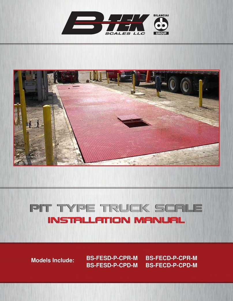
Bilanciai B-TEK Scales BT-RA-CPD User manual

INSTALLATION MANUAL
RAIL SCALE
BT-RA-CPD
Models Include:

www.B-TEK.com 2020
Rail Scale Installation Manual
2

2020 www.B-TEK.com Rail Scale Installation Manual 3
Contents
Introduction Page 4
Before Installation Page 5
Choosing a Site Page 6
Site Preparation / Foundation Page 9
Unpacking Page 9
Rail Scale Installation Page 10
Connecting Modules Page 14
Conrm Required Positioning Page 15
Grouting Page 17
Rails, Rail Clips, and Anti-Creep Devices Page 18
Connecting the Grounding Cables Page 20
Load Cell Cable Wiring Page 20
Wiring Diagrams Page 21

www.B-TEK.com 2020
Rail Scale Installation Manual
4
Introduction
This manual is meant as an installation guide for the B-TEK Railroad Approved series of full electronic railroad
track scales. Scales are available in both AAR and AREMA designs. This includes the following models:
BT-RA-CPD
The RA and RS series of railroad track scales is available in standard module lengths of 12'-6" for a "single"
and 25' for a "double". Scales are available in any combination of these module sizes, along with various ap-
proach lengths.
No physical or electrical changes / alterations may be made to the scale during installation, which may void the
warranty. This includes removal, addition or modication of any steel or components, as well as electrical or
program related items.
Check with the local Weights and Measurements authority, as well as the governing railroad prior to installation
to verify that the foundation meets all requirements, including those of the National Institute of Standards and
Technology (NIST) and specically Handbook 44. Additional requirements by the governing rail line may be
needed as well.
Prior to installation it is the customer's responsibility to verify that the equipment meets the requirements of
the application. Do not begin installation if this is unknown. It is the customer's responsibility to ensure that the
scale equipment is operated within the manufacturer's specications.
Any repairs must be performed by B-TEK Scales authorized service technicians. Failure to comply with this
policy voids all implied and/or written warranties.
General safety warnings are as follows:
• The scale is designed for vehicular trac only, do not allow any pedestrian trac on the scale
• Do not get out of your vehicle while on the scale
• Keep all hands, feet and clothing away from moving parts
• Do not exceed the specied load limit for the scale
• Do not use the scale for any other purpose than weight measurement
• Use caution when removing snow or other debris from scale deck or beneath the scale modules

2020 www.B-TEK.com Rail Scale Installation Manual 5
Before Installation
Prior to installation verify the following:
• The scale design will meet the customer's application correctly
• The scale is located so that it is aligned with existing rail track and has a minimum of 75 feet of tangent track
at each approach.
• There will be sucient drainage of water from the scale area
• The approaches on both ends are level and meet the requirements of NIST Handbook 44, requiring that the
rst 25' is on the same plane of the platform
• Do not locate electrical components near any items with magnetic material. Additionally, do not locate
Indicators in direct sunlight or in areas subject to extreme temperature changes as this may aect the
accuracy of the weighing.
• You have a copy of the scale and foundation drawings specic to this installation on site at the time of
installation
• You have a copy of this manual on site at the time of installation
• The foundation concrete has had a full twenty-eight day period for proper curing
• All installation and calibration adjustments required for the scale to perform to its specied accuracy and
operation are considered to be part of the standard scale installation.
• Installations that cannot be nished in one session must ensure that proper signage and barriers are in place
to prevent use of the scale until fully operational
• Check all state and local Weights and Measures requirements before breaking ground to ensure compliance
with all regulations.
• Obtain all necessary permits for construction.
• Check all public utilities to ensure that your site is free of underground lines, pipes or hoses.
• Have assurance that the soil at the site is capable of withstanding a minimum pressure of 4,000 psf or as
specied on the B-TEK drawing / print.
• Make sure the site does not intersect existing drains or utilities.
• All surrounding areas must drain away from the scale site.
• Ensure that all overhead objects (i.e. power lines, lights) do not interfere with unloading and setting the scale
modules with a crane.

www.B-TEK.com 2020
Rail Scale Installation Manual
6
Choosing a Site
The rst step in installing the scale is to choose an appropriate site. Pertinent steps in choosing the site are:
• Ensure that the site has adequate approaching / exiting distance to comply with state and local
Weights and Measures regulations, as well as the governing rail line requirements. Scale length and
scale elevation (maximum fall per foot allowance) will impact the total area requirement.
The site selected must meet state and local requirements. The following is taken directly from Handbook 44
(H-44) issued by the National Institute of Standards and Technology.
UR.2.6. Approaches
UR.2.6.1., Vehicle Scales - On the approach end or ends of a vehicle scale installed in any one location for a
period of six months or more, there shall be a straight approach as follows:
(a) The width at least the width of the platform, and
(b) the length at least one-half the length of the platform but not required to be more than 40 feet, and
(c) not less than 10 feet of any approach adjacent to the platform shall be constructed of concrete or
similar durable material to insure that this portion remains smooth and level and in the same plane as
the platform. However, rating of sucient strength to withstand all loads equal to the sectional capacity
of the scale may be installed in this portion. Any slope in the remaining portion of the approach shall
insure, 1) ease of vehicle access, 2) ease for testing purposes, and 3) drainage away from the scale.
The scale drawings provided meet part (a) of this requirement. The site must be located to meet parts (b) and (c).
If a combo rail / truck scale, the site should have adequate room for trucks to properly align with the platform
before pulling on. This is especially important if trucks must turn before driving onto the scale.
Trucks, engines and freight should remain on the scale for a period of time no longer than is necessary for
obtaining the vehicle weight. Drivers / passengers / pedestrians should not exit their vehicles or use the scale
platform as a walkway.
Some jurisdictions require that the scale platform be clearly visible from the location of the scale instrument.
Others will allow the use of closed circuit TV or even a voice intercom. Obtain ocial approval before starting
construction.
The B-TEK rail scales are designed and manufactured with regulations established by Handbook 44 and
adopted by the National Conference of Weights and Measures (NCWM), the Association of American Rail-
roads (AAR), and the National Institute of Standards and Technology (NIST). If the scale is intended to provide
calculated weights to the serving railroad for the purpose of revenue it shall be manufactured, installed, tested,
maintained and repaired in accordance with the Association of American Railroads Scale Handbook which con-
tains rules and specications for the construction and maintenance of track scales for the weighing of railroad
vehicles.

2020 www.B-TEK.com Rail Scale Installation Manual 7
Excerpts from the Association of American Railroads Scale Handbook include the following:
Location: Scale should be so located that an adequate foundation and at least 75 feet of tangent track at each
approach to the weigh rails can be provided.
Elevation: In areas with poor drainage, the scale shall be raised to such an elevation that drainage of the
surface water shall be away from it. Means shall be provided to prevent accumulation of water at the scale site.
Solutions for saturated areas with poor drainage shall be determined by a competent soils engineer.
Drainage: The pit oor shall be pitched to a common point for drainage and shall be smooth and free from
pockets in which water may stand. If the pit oor is below substrate water level, the pit shall be drained from its
lowest point into a sump adequately equipped with automatic means for removal of water as it collects.
Footing or Piers for load cells: Concrete footings or piers supporting load cell base plates shall not be less
than 18 inches thick. Their tops shall be above the oor a sucient distance to prevent the accumulation of
water around or under the base plates.
Pit oor: The oor of the pit may be a mat of concrete approximately as thick as that is required to support the
load cell base plates or, if local conditions permit, the thickness may be reduced to no less than 6 inches.
Ventilation: All scale pits shall be ventilated to meet the needs of each particular case to minimize the relative
humidity in the pit and to deter corrosion of scale parts and structural steel.
Entrance to Scale Pit: Suitable access to the scale pit shall be provided. The entrance shall be closed by a
suitable closure fastened to prevent the entry of unauthorized persons.
Safety Pier: Suitable piers, columns or other supports should be provided to prevent excessive drop of the
girders if there should be a failure of other scale parts. Clearance should be maintained at full scale capacity.
Bearing Pressures Under Foundations: The bearing areas of the foundation footings shall be such that the
pressure under the footings will not exceed:
Fine sand or clay 4,000 lbs per square foot
Course sand or hard clay 6,000 lbs per square foot
Boulders or solid rock 20,000 lbs per square foot
If the soil does not have a bearing capacity of at least 4,000 pounds per square foot, and its bearing capacity
cannot be increased by drainage, stabilization, or other means, pile foundations shall be provided. Careful soil
exploration, including borings, is always desirable.
Leveling: Load cell assemblies shall be raised or lowered, as required, by means of leveling screws, shims, or
other methods to bring the weighbridge into level traversely and on grade longitudinally. After leveling the load
cell base plates, to a tolerance of not more than 1/64” per foot, they shall be grouted as required.
Scale House Design: Except where the indicating elements are mounted in a separate building, a scale house
large enough to install, observe and service the indicating elements shall be provided. It should have windows
of sucient size and so located as to give the weigher an unobstructed view of the scale deck and approach-
ing cars or trucks.

www.B-TEK.com 2020
Rail Scale Installation Manual
8
Where a special scale house is required, a suitable and substantial building shall be provided. To ensure prop-
er operation of the indicator and/or recorder, the house shall be equipped with proper environmental control.
Scale House Location: The lateral clearance between the scale house and centerline of scale or any track
shall not be less than 8 feet, unless otherwise required by law, or the servicing railroad.
Indicator / Recorder Shelf: If a shelf is required for mounting the indicator and/or recorder it shall be so locat-
ed as to provide for ease of operation without obscuring the weigher’s view of the scale deck and approaching
cars or trucks. The shelf must not limit ready access to the instrument for maintenance purposes.
Power Source: The power source of the electronic instrumentation and load cell circuitry shall conform to the
following:
Voltage—115 VAC +/- 10v
Frequency—60 HZ +/- 0.25 HZ
The power source must be reasonably free from harmonics and electrical transients. Fusing shall be provided
at 15 amp unless otherwise specied by the manufacturer. The power source shall be a separate circuit back
to the distribution transformer. One side of the 115 VAC power source shall be at a ground potential. Power
surge protection shall be provided for load cells and instrumentation circuit.
Adequate protection of shielding should be provided to eliminate radio frequency and electro- magnetic inter-
ference. The scale must satisfy the tolerance requirements when the scale equipment is subjected to RFI and
EMI inuences.
Cabling: All cabling between load cells, junction boxes and electronic instrumentation shall conform to the
following:
The connection between the ground rod and the common ground point of the load cell and instrumentation
circuits shall be made with copper wire, or the equivalent of, number 10 gauge or larger.
All cable shields in the load cell circuits shall be grounded at one end only.
Homerun cables shall be physically separate from power cables and never run in the same conduit system.
All cable connections, junction boxes, etc. in the load cell circuits shall be properly protected against the eects
of moisture.
All multi-conductor cabling shall be color-coded, or provided with other means of identication of the individual
conductors.

2020 www.B-TEK.com Rail Scale Installation Manual 9
Site Preparation / Foundation
Check and review all blueprints prior to starting work. Steps to follow include:
• Use only the latest engineering drawing sent with the scale order.
• Using a transit, locate the stakes where the scale foundation will be constructed.
• Excavate to the specied elevation on the drawing / print to comply with the desired nished scale elevation.
• Construct forms and make sure they are square, plumb, and level.
• Foundation must be accurate to the blueprints within specied tolerances. The foundation must comply with
the blueprint to have an acceptable installation.
• Position cut-to-length rebar into the foundation forms as per illustrations noted on the B-TEK Scales
drawings. (Rebar conforming to ASTM 615 Grade 60 is required.)
• Concrete of 4,000 psi compressive strength is required for the foundation, and piers, if used.
• The base plates, which support the load cells, are designed to be anchored to the foundation (or pier) by
poured in place j-bolts. Existing foundations will require all thread to be drilled and epoxied into place
where required.
• All concrete work must meet standards set forth by the American Concrete Institute Code.
• Allow the concrete foundation time to cure before erecting the scale. Insucient curing time of concrete may
result in damage to the structural integrity of the scale foundation.
Unpacking
Unload the shipping crate of scale components prior to unloading scale platform modules from the truck to
verify you have everything included on the packing list.
Open all boxes for individual equipment pieces and perform a physical inspection to be certain all components
are present and have not been damaged during shipping. Any parts that are missing or damaged must be
reported immediately to qualify for warranty replacement. Digital photos that can be e-mailed are extremely
helpful.
The components included in your standard rail scale "package" will include: weighbridge modules, weighbridge
connection fasteners, load cells and load cell base plates, locating plates, shims, load cell cables, end and
side checking assemblies, conduit, and junction boxes with terminal boards. An indicator and surge protection
equipment is included with standard rail scale models. Foundation drawings and an installation manual are
included with all scales.

www.B-TEK.com 2020
Rail Scale Installation Manual
10
Rail Scale Installation
Prior to installation of the scale it is important to have the proper tools and equipment. The following is a sug-
gested list :
• A mobile crane with a minimum capacity of 11,000 LBS.
• Foundation drawings
• 4-way lifting chains with of 15' - 20' lengths to each corner
• 100' measuring tape
• Chalk line
• Laser level and/or transit
• Hydraulic bottle jack(s)
• Dummy load cells
• Various size wrenches and sockets (13mm, 9/16", 3/4", 1-1/8", 1-5/16" and 1-7/8")
• Pry bars
• Hand tools for working with cables / wires
• Level(s)
Use a string line to establish the centerline of the track through the
approaches and scale modules.
Rail Scale: Foundation Base Plate Layout
Verify that the foundation dimensions are correct and accurate, specically the distance between end walls and
the vertical height from slab / pier to top of approach.

2020 www.B-TEK.com Rail Scale Installation Manual 11
Measuring from established centerline use the provided foun-
dation drawings to snap center lines at all load cell/checking
stand foundation base plates.
Place supplied jam nuts and washers onto foundation bolts then set supplied load cell/checking stand
foundation plates to required height per supplied B-TEK foundation drawings. Ensure plates are leveled.
Install washers and nuts onto leveled plates. Fully tighten.

www.B-TEK.com 2020
Rail Scale Installation Manual
12
For each load cell in the scale, a load cell mount kit will be provided. It consists of the following:
• Lower receiver
• Upper Receiver
• Thick ring plate
• Isolation disc
• Debris foam ring
• (1) “Y” grounding strap
• (1) bag containing anti-rotation pin
Rail Scale Load Cell Mount Kit
Anti-Rotation Pin
Debris Foam Ring
Lower Receiver
Isolation Disc Upper Receiver
“Y” Grounding Strap
Install lower load cell cup ring plate to load cell foundation plate and place dummy load cell as shown.
Thick Ring Plate

2020 www.B-TEK.com Rail Scale Installation Manual 13
Place weigh bridges onto dummy pins. Verify that all four dummy stands are inserted concentrically in the
mounting plate through holes with no binding and that the bridge rests at on top of the dummy cell pins.

www.B-TEK.com 2020
Rail Scale Installation Manual
14
Connecting Modules (If Double Bridge)
With the rst end module in place you can now lift the next adjoining module into place and attach using the
supplied mounting plates and splice plates.
The module will be lowered onto the mounting plate connected to the end module that was installed rst, and
onto the dummy stands at the opposite end.
Align and install mounting plates and bolts as shown below.
Bolted Mounting Plate SHOWN with dummy pin assembly
Bolted Splice Plates SHOWN with dummy pin assembly
Horizontal
Mounting Plate
Vertical
Mounting Plate

2020 www.B-TEK.com Rail Scale Installation Manual 15
Conrm Required Positioning
Verify weight bridge is centered on established centerline of track (for side to side checking). Verify weigh-
bridge is centered and gaps are equal at each end wall (for end to end checking). If adjustments are required,
loosen the two ring plate bolts and adjust ring plate to achieve the required adjustments to center the weigh-
bridges. Re-tighten the bolts once adjustments are made.
Verify weighbridge height is level to rail approach. If height is not level adjust jam nuts under grout plates.
Place bottle jack on the weighbridge main beam and jack up scale to remove dummy pin. Install load cell and
associated components and attach ground strap as shown. Repeat above steps for each load cell location.
12mm Bolt
Ring Plate

www.B-TEK.com 2020
Rail Scale Installation Manual
16
Use B-TEK leveling tool to plum all load cells. Loosen bolts in ring plate
to adjust load cell to plum. Tighten ring plate bolts completely after load
cells are plum.
Locate checking rods, nuts and washers. Install nuts and washers as detailed in the image below.
Place assemblies into checking rod stands as shown.

2020 www.B-TEK.com Rail Scale Installation Manual 17
Fasten rods into place with remaining nuts and washers. Tighten nuts enough to prevent end to end movement
of the rod, but not so tight that the washers cannot rotate freely.
Grouting
Build grout boxes around load cell/checking stand foundation plates.
Grout Specications:
• Grout shall be precision, packaged dry, non-metallic, hydraulic,
non-shrink, and non-gaseous.
• Grout shall meet or exceed ASTM C-1107 and Corps of Engineers
CRD-C621.
• Grout shall be bleed free and attain a minimum of 8000 psi
compressive strength in 28 days at owable consistency.
• Grout MUST be mixed to a owable consistency as specied by the
grout manufacturer.
Allow enough space between inside of wooden grout box and edge of grout
plate to allow installation of grout into form/cavity.
Ensure no voids exist in grout under foundation plates.

www.B-TEK.com 2020
Rail Scale Installation Manual
18
Rails, Rail Clips and Anti-Creep Devices
The scale is designed to accept no less than 115 lb rail with Foster #62 rail clip. The approach rails and scale
weigh rail are required to be the same weight and dimension. The approach anchor bolts, approach rail plates,
rail clips, and anti-creep devices are all optional items. They can be supplied by B-TEK Scales as accessories,
however they are not supplied with order.
Approach
Anti-Creep
Device
Weighbridge
Anti-Creep
Device
Pandrol
Clips
Gantrex
Clips
#62 Rail
Clips

2020 www.B-TEK.com Rail Scale Installation Manual 19
Positive means must be provided to prevent the creeping of the approach rails and to maintain a clearance
which shall be not less than 1/8 inches or more than 5/8 inches between the approach rails and the weighrails.
The AAR Specications state that the rail on the approach and the weighbridge shall be anchored to pre-
vent creeping of the rails. This is done in order to maintain the proper gap between the approach rail and the
weighrail.
Weighbridge Approach
Weighrail Approach Rail

www.B-TEK.com 2020
Rail Scale Installation Manual
20
Connect the Grounding Cables (Rail)
Connect the grounding cables from each load cell to the threaded cable stand-o on the weighbridge.
Additionally, connect a grounding cable from the M8 bolt/nut on the locating plate to the same stand-o on the
weighbridge.
Adjacent weighbridges require an additional grounding wire from the threaded stand-o on the weighbridge
which is run to a stand-o on the next weighbridge in line.
Run a #6 ground wire from the indicator the main AC power earth (service) ground. Always establish a single
point grounding system.
Load Cell Cable Wiring (Rail)
At this point all of the load cell cables can be ran to junction boxes. As an option and at an additional cost, digi-
tal load cell cables can be requested to be pre-wired at the factory when ordering the scale.
It is important that all cables be installed so that they do not touch the ground and are internal to the scale.
Round cable hangers are attached to each module to enable you to use zip ties to secure excess cable, by
being bundled and attached to the hangers.
Depending on your particular type of Rail Scale, nd the correct wiring diagram on the following pages. Addi-
tionally, a wiring diagram was included with your “scale package” along with the foundation drawing.
Be sure that the cables are not run or bundled so tight that they cause the scale modules to bind resulting in
weight variations. After being run, connect all load cell cables to the load cells.
Note: Do not cut the load cell cables—this will void the warranty.
Weighbridge Stand-O to Stand-O
Grounding Wires Load Cell and Locating Plate Grounding
Wires to Weighbridge Stand-Os
Stand-O
Table of contents
Other Bilanciai Scale manuals
Popular Scale manuals by other brands

PCE Health and Fitness
PCE Health and Fitness BT 200 manual
Rice Lake
Rice Lake 610-10-2 Series Technical & operating instructions

Laica
Laica PS4007 Instructions and guarantee

TEFAL
TEFAL BODY UP BM252 Series instruction manual

TIROSS
TIROSS TS-1301 instruction manual

Menuett
Menuett 821-028 User instructions
