Soliton STC Zao User manual

Ver.1.0.2
STC Zao/Zao Controller/STC HDView
User Guide
Soliton Systems K.K.
Rev.1.1

- 1 -
LEGAL NOTICES
The copyright and any other rights concerning “Smart-telecaster Zao,” “STC Zao,” “Zao
Controller,” and “STC HDView” belong to Soliton Systems K.K.
Windows is a trademark of Microsoft Corporation.
VP8 is a patent-protected Google product.
Other patents, trademarks, and copyrights included herein are the property of their respective
owners.
AES library of Mr. Isao Mori is stored in this product.
Reproducing or modifying any portion of the product is prohibited.
Design and specifications subject to change without notice.
The connection condition written in this book is one example that does not provide a guarantee.
Soliton Systems K.K.
2-4-3 SHINJUKU, SHINJUKU-KU, TOKYO 160-0022 JAPAN

- 2 -
CONTENTS
1Overview ...............................................................................................................................................4
2Safety Information ...............................................................................................................................5
2.1 Handling the Power Supply and Battery Equipment..................................................................... 5
2.2 Additional Warnings.......................................................................................................................... 5
3Product Specifications.........................................................................................................................6
3.1 STC Zao Specifications ..................................................................................................................... 6
3.2 STC HDView Specifications .............................................................................................................. 7
4Notice....................................................................................................................................................8
5STC Zao Assenbly ................................................................................................................................9
5.1 Outline and connection method ..................................................................................................... 9
5.1.1 Front side .................................................................................................................................... 9
5.1.2 Upper Side................................................................................................................................. 10
5.1.3 Left side, Right side................................................................................................................. 11
5.1.4 Power Supply ............................................................................................................................ 11
5.2 Usage ................................................................................................................................................ 12
5.2.1 Startup ....................................................................................................................................... 12
5.2.2 LIVE mode ................................................................................................................................. 12
5.2.3 SETTING mode.......................................................................................................................... 14
5.2.4 POWER mode............................................................................................................................. 17
5.2.5 Power off ................................................................................................................................... 17
5.2.6 Operation Lock......................................................................................................................... 18
5.2.7 LED ............................................................................................................................................. 19
6Zao Controller ....................................................................................................................................20
6.1 Usage ................................................................................................................................................ 20
6.2 Install ................................................................................................................................................ 20
6.3 How to connect ................................................................................................................................. 20
6.4 Usage................................................................................................................................................. 20
6.4.1 Startup ....................................................................................................................................... 20
6.4.2 Main Screen............................................................................................................................... 21
6.4.3 Network settings...................................................................................................................... 23
6.4.4 Video and Audio setting ......................................................................................................... 24
6.4.5 Setting destination................................................................................................................... 27
6.4.6 Preset screen ............................................................................................................................ 29
6.4.7 Setup screen ............................................................................................................................. 31

- 3 -
7STC HDView........................................................................................................................................34
7.1 Requirements for Receiver............................................................................................................. 34
7.2 Startup .............................................................................................................................................. 36
7.2.1 Main screen ............................................................................................................................... 36
7.3 Audio Input/Output.......................................................................................................................... 40
7.4 Edit Settings..................................................................................................................................... 41
7.5 Common settings.............................................................................................................................. 45

- 4 -
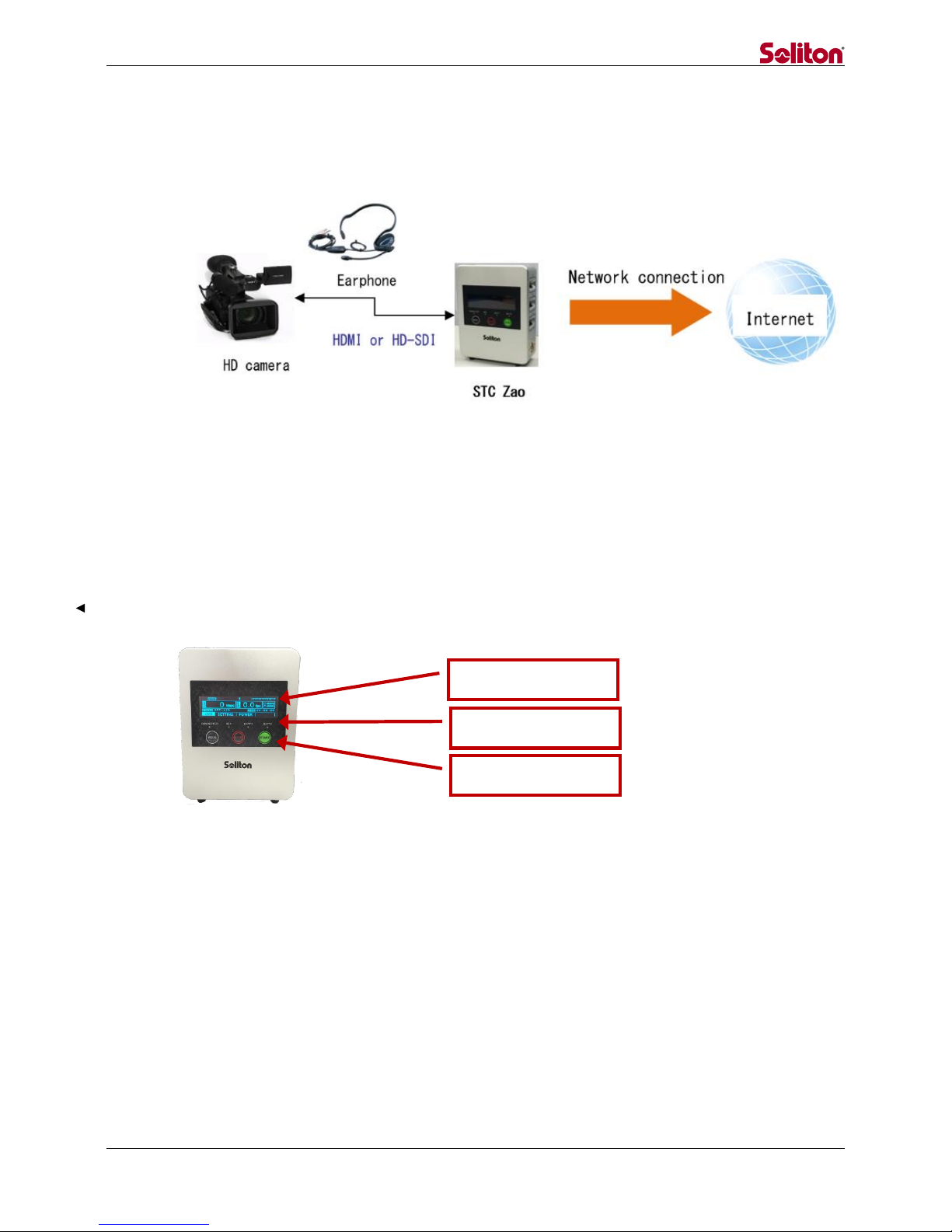
1 Overview
The Smart-Telecaster Zao (“STC Zao”) is a system for transmitting HD video and audio in IP
communications network. The STC Zao offers voice communication, unidirectional video
transmission, and two-way video transmission, all of which allow access to remote location
events in real time.
The system contains STC Zao that uses up to seven communication lines transmitting the
image captured by the camera, Zao Controller that controlls the STC Zao remotely, and STC HD
View that displays a received video
Figure 1. Connection Options
These operating instructions refer to the equipment configuration and method of operation of
the Transmitter/Receiver.

- 5 -
2Safety Information
WARNING! Be sure to read all safety precautions before operating the STC Zao or any of its
components.
2.1 Handling the Power Supply and Battery Equipment
Risk of electrical fire or shock
Keep product away from heat.
Do not handle the power adapter or battery equipment with wet hands.
Do not forcibly bend or twist the power cable.
Do not plug in the power adapter in the octopus legs wiring.
2.2 Additional Warnings
Risk of product failure
Do not leave the product in direct sunlight for an extended period of time.
Do not drop the product of place heavy products on top of it.
Do not attempt to disassemble the product.
Do not use any type of power source other than that indicated in these instructions.
Risk of serious injury
Discontinue use if product begins to smoke.
Do not use product if any parts are damaged.
Do not use product if it feels hot to the touch.
Do not use product of it emits an unusual smell.
Do not use the product if any liquids or other foreign matter are inside.

- 6 -
3Product Specifications
3.1 STC Zao Specifications
ITEM
DETAILS
Weight
900g
Dimension
123mm×160mm×46mm
Power Connector
Cannon4pin × 2
LAN
RJ45 × 1
Video Input
HD-SDI
BNC × 1
HDMI
HDMI × 1
Input
1080/59.97i, 1080/50i
480/59.97i, 576/50i
USB for Modem
USB2.0 × 6
Headphones output
3.5Φjack × 1
Accessories supplied
AC Power× 1
V-mount battery plate × 1
USB cable with latch × 6
HDMI cable with fixing screw× 1
USB memory (housing) × 1
WiFi dongle(housing) × 1
Transition bag × 1
CD-ROM × 1
Main Function
Live Relay(One-way video, Two-way audio)
Communication
Line
3G、LTE、Wireless LAN、Wired LAN、Satellite
Error Correction
ARQ、Packet sort
Protocol
UDP/IP(RASCOW)
Encryption
AES256bit
Authentication
Passphrase(Up to 32characters)
Multilink
Up to 7 lines
Connecting Method
Manual, Startup automatic, Reconnecting
Non-Communication
limit
Max 30sec
Video
Codec
H.265 Main Profile
Pixels(NTSC)
Max 720×480
Pixels(PAL)
Max 720×576
Pixels(HD)
Max 1920×1080
Bitrate
200kbps~10Mbps
Framerate
Max 29.97fps (NTSC,59.94 field per sec)
Max 25fps (PAL, 50 field per sec)

- 7 -
Audio
Codec
Vorbis
Channel
Stereo/Mono×1ch
Sampling
16bit、48KHz、22.05KHz、11.05KHz、8KHz
Input
Embedded Audio
Output
Analog・audio output×1
3.2 STC HDView Specifications
ITEM
DETAILS
Main Function
Live Relay(One-way video, Two-way audio)
Accumulation file reception*, file reception *,
Still image capture*
*: not supported by Zao
Connection Possible Product
STC Zao、STC HDCam、Smart-telecaster for iOS ML
Available concurrent connections
4
Delay
240msec~30000msec
Codec
Video
VP8、H.265
Audio
Vorbis
Operating
Environment
Hardware
HP Z420 Workstation
OS
Windows7 Professional
CPU
Intel Xeon
Memory
8GB+
(Four of the same physical memory is required)
External
Output
Video Card
Blackmagic Design Decklink Quad (4output)
Signal Format
SDI or HD-SDI(By the transmitter connection)

- 8 -
4Notice
The accompanying AC adapter is AC100V ~ 240V, 50Hz / 60Hz support, but the power cable
is domestic only.
IDX Inc. V-mount battery recommended
If you do not use the product for a long time, please remove the battery and AC adapter.
STC Zao employs an audio sampling rate of 48KHz
STC Zao features a Wi-Fi dongle with USB memory. Do not remove it.
The modem can be set only with the Zao Controller. It cannot be set from the STC Zao. Once
you have set the modem, you do not need to set it again.
Note: This equipment has been tested and found to comply with the limits for a Class A digital
device, pursuant to part 15 of the FCC Rules. These limits are designed to provide reasonable
protection against harmful interference when the equipment is operated in a commercial
environment. This equipment generates, uses, and can radiate radio frequency energy and, if
not installed and used in accordance with the instruction manual, may cause harmful
interference to radio communications. Operation of this equipment in a residential area is
likely to cause harmful interference in which case the user will be required to correct the
interference at his own expense.
- 9 -
5STC Zao Assenbly
This chapter describes STC Zao, connection procedures and the preparation.
Figure 2. Connection Option for the STC Zao
5.1 Outline and connection method
5.1.1 Front side
Front side of STC Zao consists of a display, LEDs and operation buttons.
Figure 3. Front View of STC Zao
Display
LED
Operation button

- 10 -
◆Display
The display describes the status of the camera connection, status of the network
connection, bit rate, frame rate, status of video transmission, time of live
broadcasting, etc.
*Please refer to “5.2.2 LIVE mode” for more detail.
◆LED
CONNECTED ········Displays the connection status.
REC···············Displays the record status.
*Record function will be available in a future version.
BATT1·············Displays the battery status of Main power supply.
BATT2·············Displays the battery status of Sub power supply.
*Please refer to “5.2.7 LED” for more detail.
◆Operation button
MODE ·············Switch LIVE mode/SETTING mode/POWER mode.
STOP··············Stop live broadcasting, power off
START·············Start live broadcasting, final determination
(Power off/Live broadcasting end)
MODE+START (Long press) Operation lock
5.1.2 Upper Side
Wi-Fi dongle and USB port for outputting log are positioned on the upper side.
Figure 4. Upper Side View
*In case of using HD-SDI and HDMI at the same time, HD-SDI takes precedence.
LAN connector
Power switch
WiFi dongle
Earphone jack
HD-SDI connector
HDMI connector
USB for outputting log

- 11 -
5.1.3 Left side, Right side
The left side features three modem connectors and the main power connector while the right
side has three modem connectors and the sub power connector.
Figure 5. Right and Left Side Views
5.1.4 Power Supply
The STC Zao power supply prioritizes the main power connector.
For example, when connecting a battery to main power connector and connecting a power
adapter to sub power connector, the unit draws power from the battery connected to main
power connector. When the battery runs out, the unit switches to sub power automatically.
The unit even runs only with sub power.
Battery
*When using a battery, use a bundled V-mount
battery plate.
Power adapter
*When plugging in the unit, use a bundled AC
adapter and power cable.
Modem connector
*In case of using a modem
connector, use a bundled USB
cable of latch structure.
Left side
Right side
- 12 -
5.2 Usage
5.2.1 Startup
Push the power button on the upper side to start the STC Zao. STC Zao supports the following
operation modes. (To switch modes, push “MODE” button.)
Mode name
Usage
Switching method
LIVE mode
Broadcast live
Initial state
SETTING mode
・Confirm the version
・Select the destination
・Initialize the configuration
・Update STC Zao
・Connect for remote maintenance
Press “MODE” button once in
the initial state
POWER mode
Shutdown STC Zao
Press “MODE” button twice in
the initial state
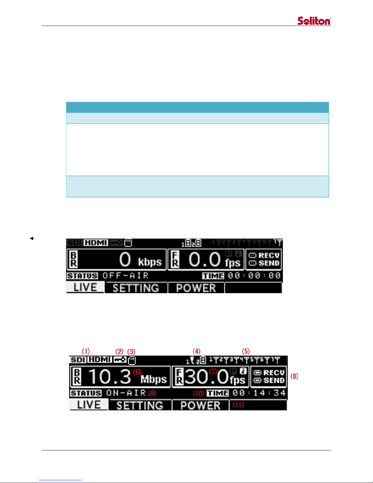
5.2.2 LIVE mode
This mode transmits real-time video and audio. The following screen displays the initial state.
Figure 6. LIVE Mode (Initial State)
Press the “START” button in the initial state to start live broadcasting and display the following
screen. Press the “STOP” button to return to the initial state.
Figure 7. LIVE Mode (Live Broadcasting)

- 13 -
(1) Status of camera connection
Displays the status of camera connection (HDMI/SDI/No connection).
(2) Status of encryption
Displays the status of encryption.
(3) Status of USB memory connection for log output
Displays the status of the USB memory connection for log output.
(4) Status of power equipment connection
Displays the status of butteries / power adapters connecting main power and sub power.
(5) Status of network connection
Displays the status of the network from 1 to 7.
(6) Bit rate
Displays the communication band currently used.
(7) Frame rate
Displays the frame rate.
(8) Communication indicator [RECV, SEND]
Flashes on and off when communication occurs.
(9) Status of connection
Displays the connection status of connection
(Connecting/ON-AIR/Disconnecting/OFF-AIR).
(10) Connection time
Displays the connection time of live broadcasting.
(11) Mode
Displays the current mode (LIVE/SETTING/POWER).
- 14 -
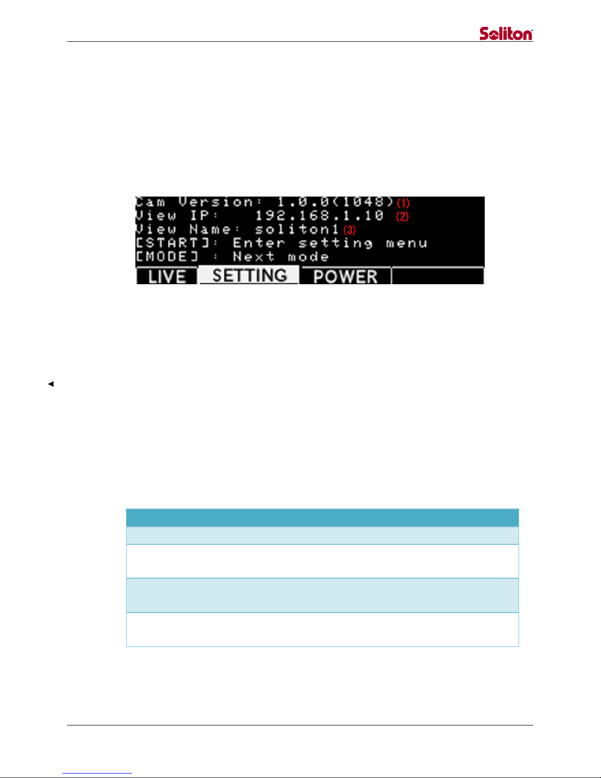
5.2.3 SETTING mode
This mode enables version confirmation, destination setting, initialization, firmware update,
and remote maintenance connection.
5.2.3.1 SETTING mode (Cam Version)
The top level of “SETTING” mode displays the following screen.
Figure 8. SETTING Mode (Version confirmation)
(1) Version
Displays the version of firmware.
(2) Destination IP address
Displays the destination IP address.
(3) Destination name
Displays the destination name.
SETTING mode supports the following operations.
Operation
Usage
Switching method
VIEW IP SELECT
Select the destination
Press “START” once
FACTORY RESET
Initialize the configuration
Press “START” once, and then
press “MODE” once
FIRMWARE UPDATE
Update the firmware
Press “START” once, and then
press “MODE” twice
REMOTE SUPPORT
Connect remotely for
remote maintenance
Press “START” once, and then
press “MODE” three times
- 15 -
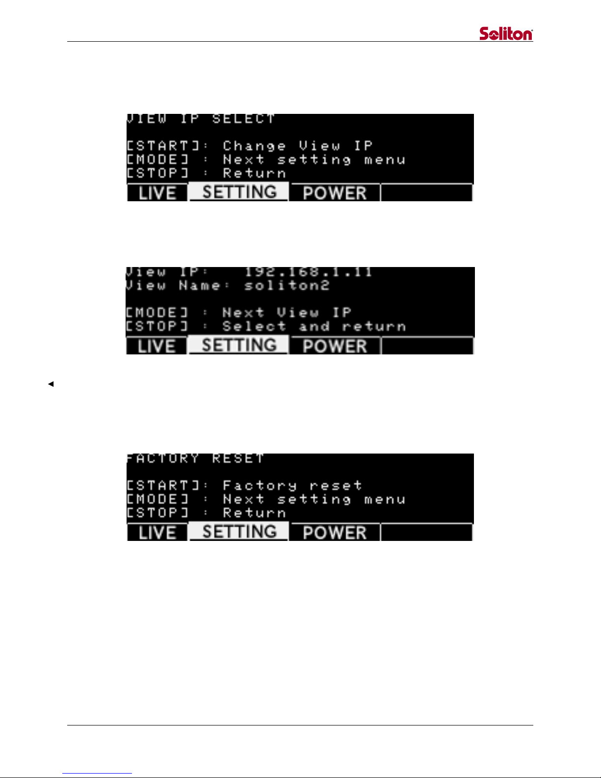
5.2.3.2 SETTING mode (IP Select)
The SETTING mode (IP Select) displays the following screen.
Figure 9. SETTING Mode (IP Select)
Press the “START” button to display the following screen
Figure 10. SETTING Mode (IP Select)
5.2.3.3 SETTING mode (Factory Reset)
The SETTING mode (Factory Reset) displays the following screen.
*This function will be available in a future version
Figure 11. SETTING Mode (Factory Reset)
- 16 -
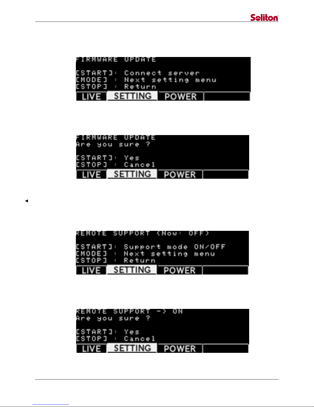
5.2.3.4 SETTING mode (Firmware Update)
The SETTING mode (Firmware Update) displays the following screen.
[NOTE] When installing a firmware update, use a wired LAN network.
Figure 12. SETTING Mode (Firmware Update)
Press the “START” button to display the following screen.
Figure 13. SETTING Mode (Firmware Update Confirmation)
5.2.3.5 SETTING mode (Remote Support)
The SETTING mode (Remote Support) displays the following screen.
[NOTE] For remote maintenance, use a wired LAN network.
Figure 14. SETTING Mode (Remote Support)
Press the “START” button to display the following screen.
Figure 15. SETTING Mode (Remote Support Confirmation)

- 17 -
5.2.4 POWER mode
POWER mode supports the following operations.
Operation
Usage
Switching method
Power off
Shutdown STC Zao
Press “START” button once
*Pressing “START” button,
shutdown processing starts
The POWER mode displays the following screen
Figure 16. POWER Mode (Initial State)
Press the “START” button to display the following confirmation screen.
Figure 17. POWER Mode (Power Off Confirmation)
5.2.5 Power off
Besides the POWER mode, the following operation will shut down the unit.
Operation
Usage
Switching method
Power off
Shutdown STC Zao
In a state of no live
broadcasting, press the “STOP”
button for three seconds.

- 18 -
Press the “STOP” button for three seconds to display the following screen.
Figure 18. Power Off Confirmation
5.2.6 Operation Lock
Operation lock supports the following operations.
Operation
Usage
Switching method
LOCK
All of the button
operations are disabled.
Pressing “MODE” and “START”
buttons for five seconds.
*Pressing the buttons for five
seconds again cancels the lock.
Once button operation is locked, display the following screen.
Figure 19. Button Operation Is Locked

- 19 -
5.2.7 LED
5.2.7.1 Startup
When the STC Zao starts, four LEDs flash on and off from the left.
When the startup is completed, the LEDS turn off and the screen displays LIVE mode.
5.2.7.2 Connecting
When a connection to STC HDView is completed, the CONNECTED LED flashes on and
off with yellow green.
During processing of connection and disconnection, the LED flashes on and off with
yellow green. Once the unit is disconnected, the LED turns off.
5.2.7.3 Battery State
Once the battery is mounted, the BATT1(Main) and BATT2(Sub) LED flashes on and off.
When battery power decreases, the LED flashes on and off.
5.2.7.4 Shutdown
When the STC Zao shuts down, four LEDs flash on and off at once.
When the shutdown is completed, the LEDS turn off.
This manual suits for next models
2
Table of contents


