
ECX 1U/2U INSTALLATION GUIDE PX106483-EN REV A Page 4 of 22
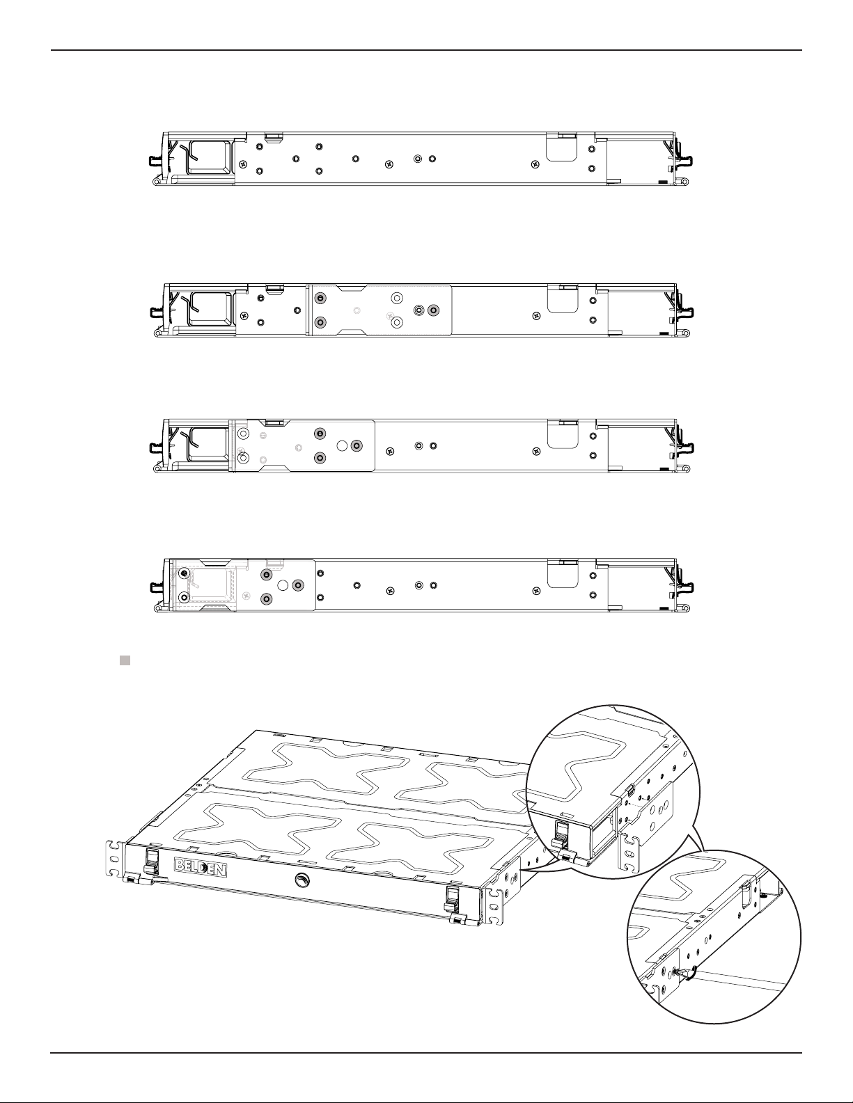
2. Carton contents
1. Removable top covers (2x)
2. Rear door
3.Housing
4.Front door
5.Sliding tray
6.Patch cord management clips
(3x for ECX 1U and 6x for ECX 2U)
7. Labels cards (2x)
8.Installation guide [ECX: Splice
cassette and 1U/2U QSG - not shown]
9. Hardware kit [not shown]
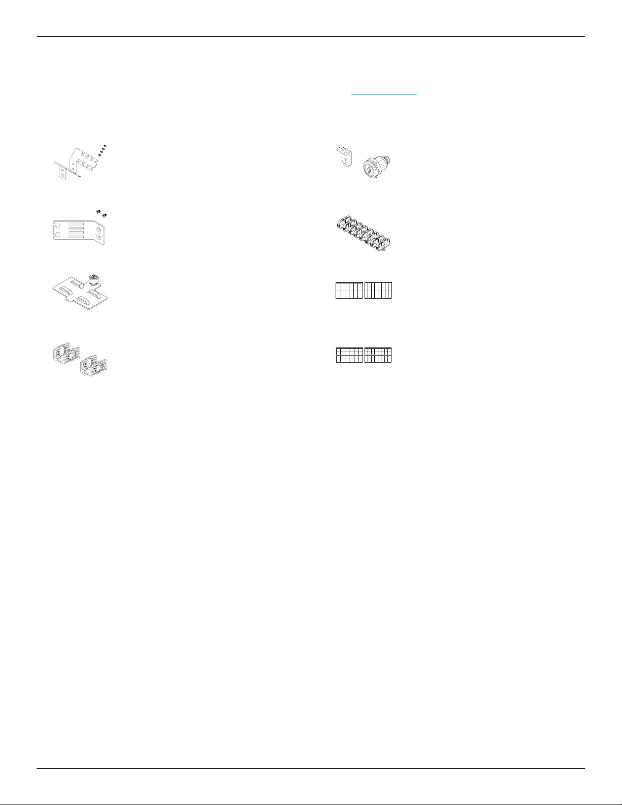
2.1. Hardware kit contents
1. Blank frames
2. Management clips
3. Intermediate strain relief
4. Internal strain relief
5. External strain relief [*R&L]
6. M4 x 5mm - Metric screw
7. #6-19 x ¼” - screw for plastic
8. #6-19 x ½” - screw for plastic
9. #12-24 - machine screw
10. #10-32 - machine screw
11. 4” self-locking cable tie
12. 7” self-locking cable tie
13. 8” Velcro cable tie
14. [3/6/12] I.D label ports
15. [8/16] I.D. label ports
16. Door lock opening cap
Contents quantity
Part # ECX 1U ECX 2U
1. 2x 4x
2. 8x 8x
3. 1x 2x
4. 1x 1x
5*.R= 1x, L= 1x R= 1x, L= 1x
6. 4x 4x
7. 4x 4x
8. 2x 2x
9. 4x 4x
10. 2x 2x
11. 4x 4x
12. 4x 4x
13. 4x 4x
14. 2x 2x
15. 2x 2x
16. 2x 2x
*R&L= Right and left sides
NOTE: Refer to section 10.2. to see detailed
illustrations of I.D. labels.
RL
1U label
1U label
1U2U


 user manual")


