Belimo Gateway MP to Modbus RTU
T9-UK24MOD • en • v1.7 • 02.2014 • Subject to changes
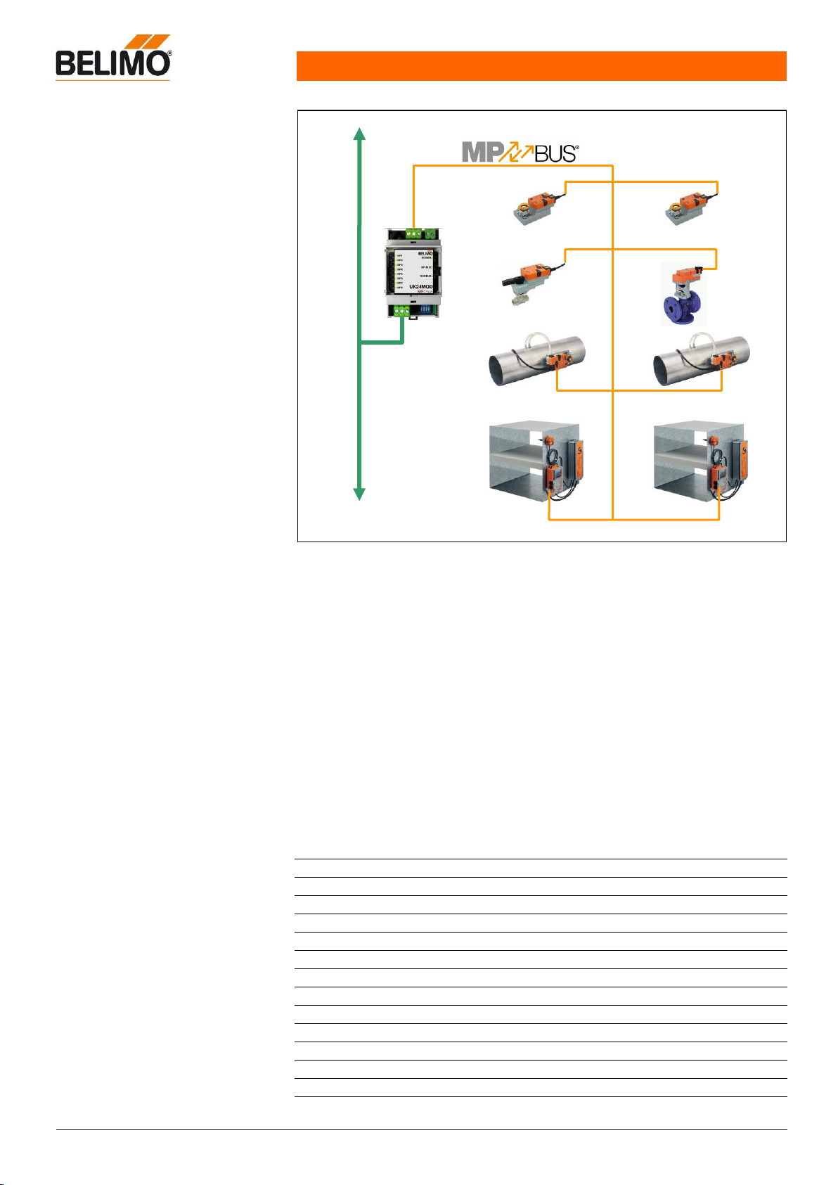
Gateway MP to Modbus RTU. MP-bus-
capable Belimo actuators can be
connected on the MP-Bus side.
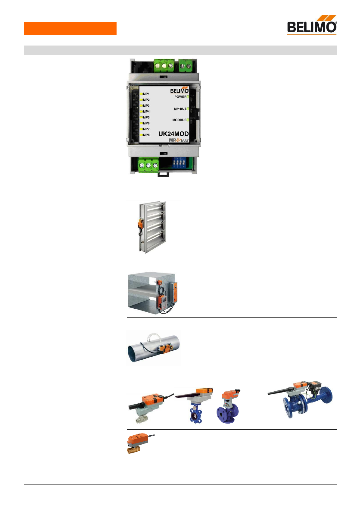
Interface MP/Modbus RTU
Connection of MP/MPL/MFT(2)
actuators and BF-TopLine
actuators to Modbus RTU
Up to 8 actuators and sensors can
be connected
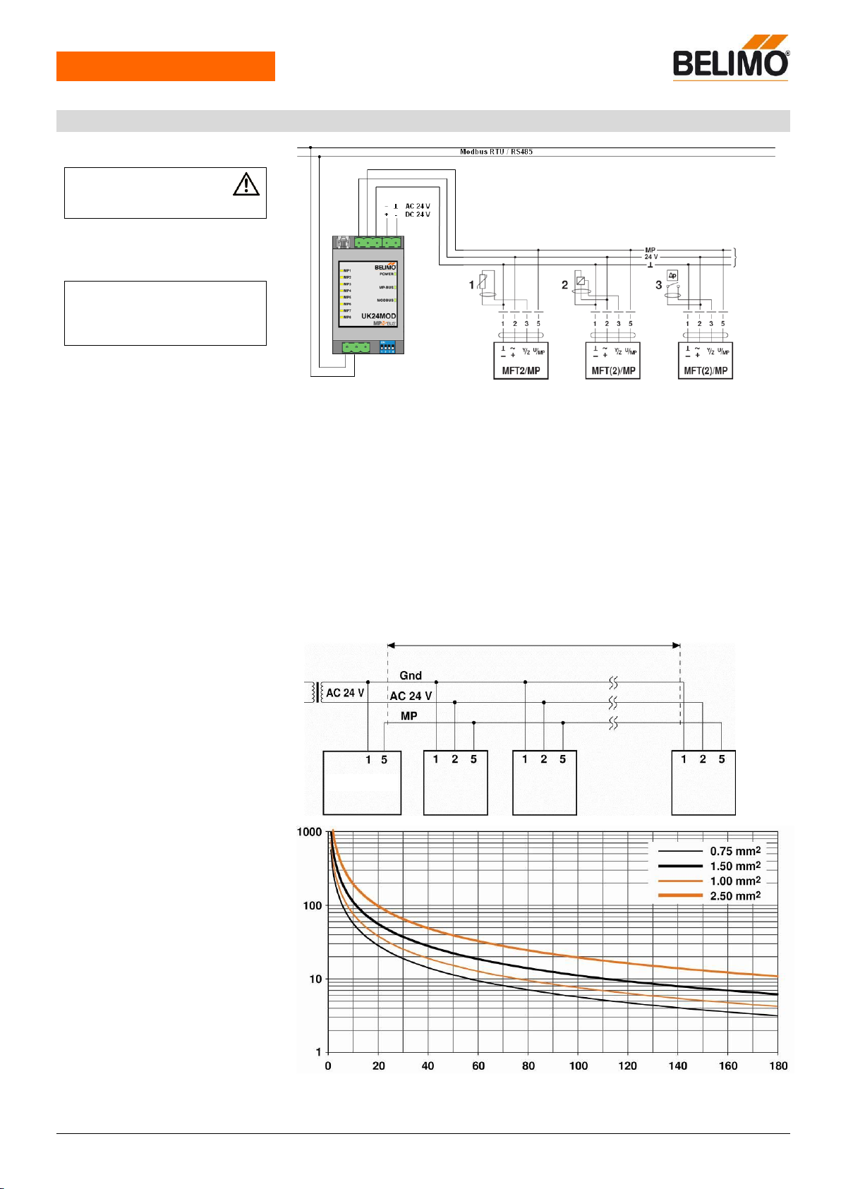
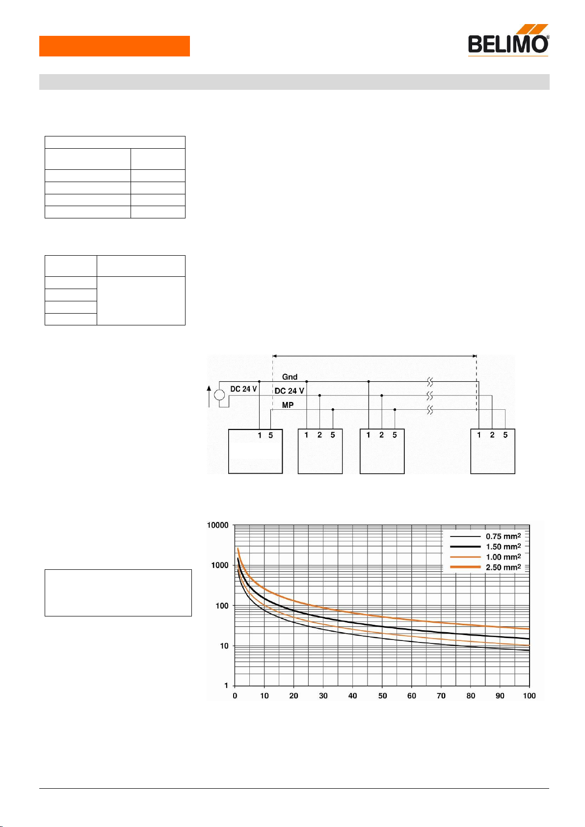
AC 24V, 50/60 Hz / DC 24V
Modbus RTU
Supply
MP-Bus
Tool
Plug-screw terminal, 3-pin
Plug-screw terminal, 2-pin
Plug-screw terminal, 3-pin
(All terminals suitable for 2 x 1.5 mm2)
RJ12
MP/MPL/MFT(2), BF-TopLine
Communication with actuators
Belimo MP-Bus, Master-Slave, 1200 Bd
Maximum signal conductor lengths MP
Dependent on the number of connected actuators,
actuator type, type of supply and signal conductor
cross-section
For details see page 5
Modbus RTU
Supported functions: 3, 6
(For register assignment, see page 11)
Medium
Parity
Number of nodes
Baud rates
Response delay
Termination
Polarisation
RTU / RS-485
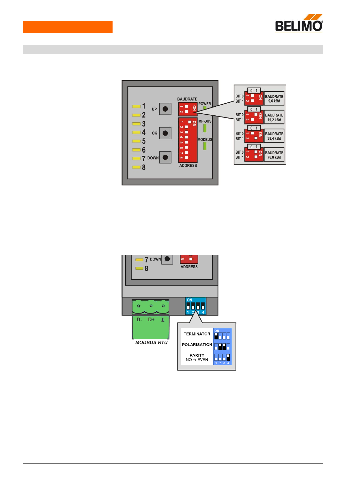
NONE (1, 8, N, 2) or EVEN (1, 8, E, 1),
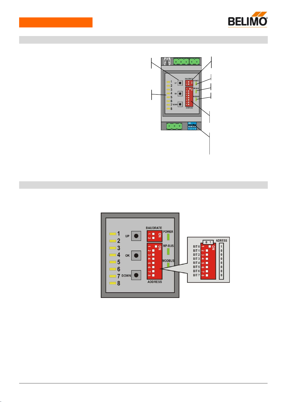
adjustable via DIP switch
max. 32 (without repeater)
9'600, 19'200, 38'400, 76'800 Bd,
adjustable via DIP switch
2…100 ms, adjustable via register
150
, adjustable via DIP switch
680
, adjustable via DIP switch
III Safety extra-low voltage
CE pursuant to 2004/108/EC
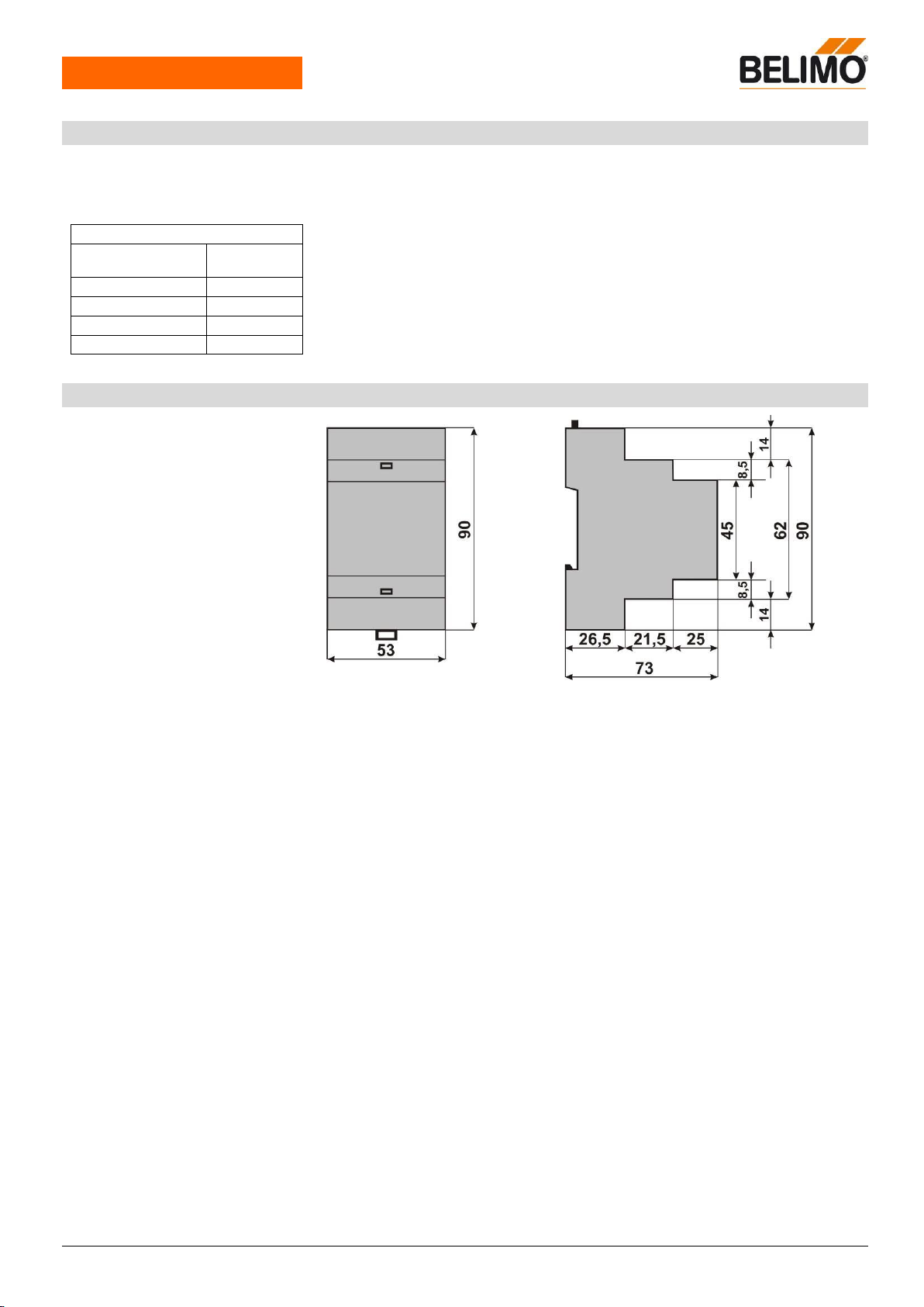
Installation / Dimension / Weight
Control cabinet installation,
can be snapped onto top hat rail 35 mm