Belimo UK24LON User manual
2. + 4. + 5. + 6. UK-4
Product Information
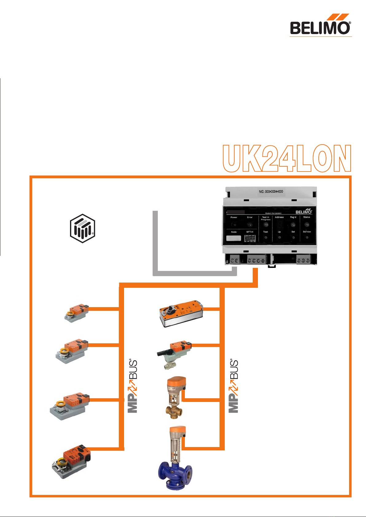
UK24LON Gateway MP/LONWORKS
®
UK24LON
LONWORKS®
▼
▲
▼
LONMARK
®
UK24LON
i0385102
(( Seite 17/18: Nur für Print A3 gemacht ))
5 year
warranty
On site around
the globe
A complete
range of products
from one source
Tested quality
Short delivery
times
Comprehensive
support

Typical applications of UK24LON unit 3
UK24LON unit data sheet 4
UK24LON unit dimensions 5
Complete MFT(2)/MP assortment 5
Connecting MFT(2)/MP actuators 6
Connecting sensors 6
MP-Bus conductor lengths 7
Functional Profile 8– 9
SNVT functions of the function objects 10
Operation, Characteristics 12–13
Connecting MFT parameterising tools 13
2
LONMARK
®
Table of Contents
MP-Bus
LONWORKS®
t
UK24LON
Various sensors
Power supply and communication
via 3 conductors only
IRC Control
for LONWORKS®
Communication
via 2 conductors
3
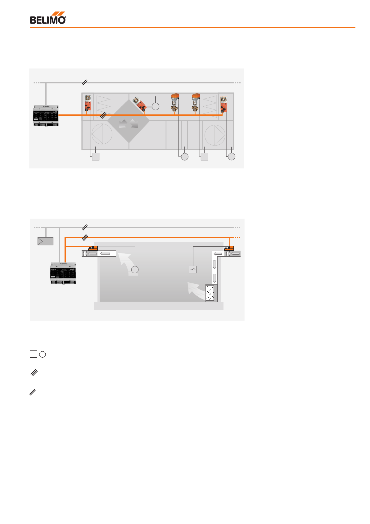
Example 1: Connecting the actuators and sensors in the plant room
of a central ventilation system to L
ONWORKS® via a UK24LON unit
Example 2: VAV-Control with a link to LONWORKS®
The plant room of a central ventilation
system employing Belimo MFT(2)/MP ac-
tuators (for air dampers and valves) can
be bus-linked to LONWORKS®. A UK24LON
unit (MP/LON Gateway) is used to link
the MP-Bus-capable actuators and the
sensors that are connected to them to the
LONWORKS® system.
ENG · 01.07· PDF · Subject to technical changes
i0387102
MP-Bus
∆p
LONWORKS®
∆pt
t
t
UK24LON
Typical applications of the UK24LON
VAV air volume controllers for supply air
and exhaust air employing VAV-Compact
(LMV-D2-MP, NMV-D2-MP or SMV-D2-
MP) motorised actuators can be linked
together via an MP-Bus.
The VAV devices and the sensors con-
nected to them (presence and tempera-
ture sensors) are linked to LONWORKS®
through a UK24LON unit (MP/LON Gate-
way). The UK24LON provides the actua-
tor functions and sensor values to the
LONWORKS® network via standardised
network variables (SNVT). The actuator
functions and sensor values can be link-
ed via the SNVTs to the IRC individual
room controller, which takes on the cont-
rol tasks for the individual room.

Gateway MP to LONWORKS®
● MP/LON interface
● MFT(2)/MP actuators (with MP
communications capability)
linked to LONWORKS® through
a UK24LON unit
● Up to 8 actuators
can be connected
● LONMARK® certified
Application
The UK24LON unit is a Belimo gateway
that has been certified by LONMARK®. It
allows the Belimo MP-Bus to be linked to
LONWORKS®.
Up to 8 MP capable actuators can be
connected to the MP-Bus side of the sys-
tem (damper actuators, valve actuators
and VAV-Compact).
Mode of operation
Through the UK24LON unit the actua-
tors can be controlled digitally over the
MP-Bus and they also provide feedback
of their current operating status. In the
UK24LON unit the digital data for control
and feedback is converted to standard
network variables (SNVT’s). This allows
the functions of the actuators to be linked
directly to LONWORKS®.
Sensor connection
One sensor can be connected to each
MFT2 actuator. It can be either a passive
resistance-type sensor (Pt1000, Ni1000
or NTC), an active sensor (e.g. with a
DC 0...10 V output) or a switching con-
tact. This provides a simple means of
digitising the analogue signal from the
sensor through the actuator so that it
can be passed on to LONWORKS® via the
UK24LON unit.
Parameterising MFT(2)/MP actuators
Using the Belimo PC-Tool it is very easy to
preset specific parameters (e.g. running
time) for individual actuators. An MFT pa-
rameterising tool can be connected to the
3-pole plug socket of the UK24LON unit.
Important installation note!
Do not energise the system
(UK24LON and actuators) until
all the wiring has been finished.
4
Technical data UK24LON unit
Power supply AC 24 V 50/60 Hz, DC 24 V
Functional range AC 19.2...28,8 V, DC 21.6...28.8 V
For wire sizing 3 VA (without MFT(2)/MP actuators connected)
Power consumption 1.5 W
Connections LONWORKS®: push-screw terminals, 2-pole
Power: push-screw terminals, 3-pole
MFT(2)/MP- push-screw terminals, 4-pole
actuators: (all terminals for 1,5 mm2)
MFT-H: plug socket, 3-pole
(for MFT parameterising tools)
Processor/Memory Neuron 3150®; 10 MHz; 48 kB flash memory, 8 kB RAM
Transceiver FTT-10A compatible with LPT-10
Functional Profile Damper Actuator 8110; see page 8
For further detailed information refer to the LONMARK®
web site (www.lonmark.org)
LNS-Plug-In The following are available for LonMaker 2.0:
(configuration Modifiable – MFT(2)/MP actuator addresses
software) with Plug-In: – Min./Max. limits
– Definition of sensors connected
to the MFT(2)/MP actuators
Communication with Belimo-MP-Bus: Master-Slave system 1200 Baud
MFT(2)/MP actuators
No of
MFT(2)/MP
actuators up to 8 actuators can be connected
Maximum MP Depends on the number of MFT(2)/MP actuators connected,
conductor length types of actuators, type of power supply and crosssectional
area of the conductor. Refer to the diagram on page 7
LONWORKS® In accordance with Echelon recommendations
conductor lengths and
transmission media
Ambient temp. range 0 ºC...+50 ºC
Protection class (safety extra-low voltage)
Degree of protection IP20
EMC CE in accordance with 89/336/EU, 92/31/EU, 93/68/EU
Mounting DIN rail 35 mm
Weight ca. 500 g
24 V
MP
T
~/+
~
-+
T
AC 24 V
DC 24 V
Connect
through a safety
transformer
MP-Bus
MP-Bus
It is essential to take account of the dimen-
sion data of the connected MFT(2)/MP
actuators when selecting the ratings for the
power supply.
LONWORKS®
!
III
ENG · 01.07· PDF · Subject to technical changes
UK24LON
UK24LON

5
105 20
41 10
58
95
45
62
90
UK24LON unit dimensions
Complete MFT(2)/MP
assortment for connection
to the UK24LON
ENG · 01.07· PDF · Subject to technical changes
d0096102
Damper actuators with or without
safety function
Actuators for characterised control
ball valves with or without spring-
return function
MP-VAV devices
Actuators for globe valves with or
without spring-return function
Actuators for butterfly valves
UK24LON unit dimensions, connectable actuators
Connect through
a safety trans-
former
~
-+
T
AC 24 V
DC 24 V
!
6
Power
Error
MFT - H
UK24LON
Service
Made in Switzerland
Status
Node
IC-DZ.03
Test
Test in
Progress
Address
Select
Up
Set
Reg'd
MP-Com.
24V0V YU/MP
Power
n.c.
LonTalk
a b
24V0V
BC
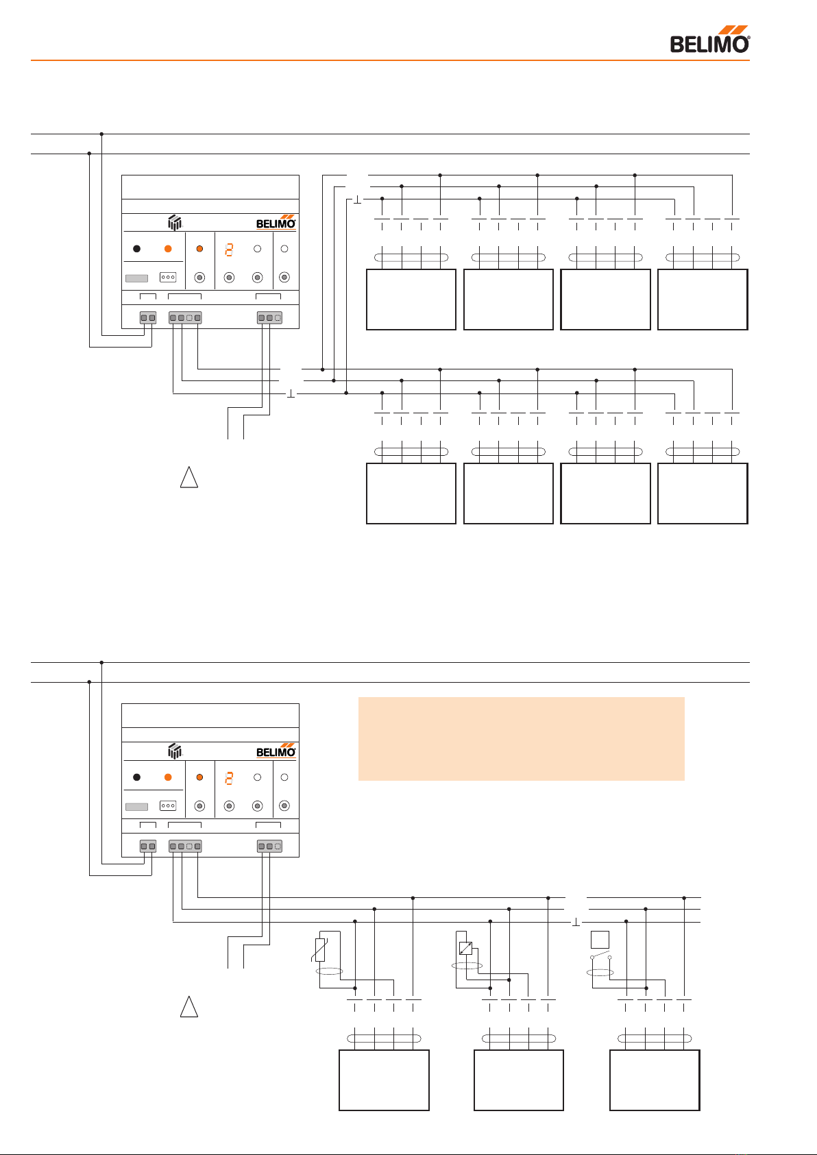
Connecting MFT(2)/MP actuators
Connecting sensors
1 2 35
T
~
-+
MFT(2)/MP-Antrieb
U/MP
Y
/Z
1 2 35
T
~
-+
MFT(2)/MP-Antrieb
U/MP
Y
/Z
1 2 35
T
~
-+
MFT(2)/MP-Antrieb
U/MP
Y
/Z
1 2 35
T
~
-+
MFT(2)/MP-Antrieb
U/MP
Y
/Z
1 2 35
T
~
-+
MFT(2)/MP-Antrieb
U/MP
Y
/Z
1 2 35
T
~
-+
MFT(2)/MP-Antrieb
U/MP
Y
/Z
1 2 35
T
~
-+
MFT(2)/MP-Antrieb
U/MP
Y
/Z
1 2 35
T
~
-+
MFT(2)/MP-Antrieb
U/MP
Y
/Z
When rating the power supply
do not forget to include the
MFT(2)/MP actuators that are
also connected.
LONWORKS®
1 2 35
T
~
-+
MFT(2)/MP-Antrieb
U/MP
Y
/Z
1 2 35
T
~
-+
MFT(2)/MP-Antrieb
U/MP
Y
/Z
1 2 35
T
~
-+
MFT(2)/MP-Antrieb
U/MP
Y
/Z
LONWORKS®
More actuators
and sensors
(total 8)
∆p
One sensor can be connected to each
MFT(2)/MP actuator. It can be either a pas-
sive resistance-type sensor (e.g. Pt1000,
Ni1000 or NTC), an active sensor (e.g.
with a DC 0...10 V output) or a switching
contact. This provides a simple means
of digitising the analogue signal from the
sensor through the actuator so that it
can be passed on to LONWORKS® via the
UK24LON unit.
Connecting
passive sensors
(Pt1000, Ni1000, NTC)
Connecting
active sensors
(permitted input
voltage range 0…32 V)
Connecting
external switches
(e.g. pressure monitors)
Power
Error
MFT - H
UK24LON
Service
Made in Switzerland
Status
Node
IC-DZ.03
Test
Test in
Progress
Address
Select
Up
Set
Reg'd
MP-Com.
24V0V YU/MP
Power
n.c.
LonTalk
a b
24V0V
BC
Power
Error
MFT - H
UK24LON
Service
Made in Switzerland
Status
Node
IC-DZ.03
Test
Test in
Progress
Address
Select
Up
Set
Reg'd
MP-Com.
24V0V YU/MP
Power
n.c.
LonTalk
a b
24V0V
BC
MP
24V
MP
24V
MP
24V
~
-+
T
AC 24 V
DC 24 V
Connect through
a safety transformer
!
When rating the power
supply do not forget to include
the MFT(2)/MP actuators that
are also connected.
ENG · 01.07· PDF · Subject to technical changes
w1123102w1126102
�
Note:
... MFT = Active sensors and switches can be
connected
... MFT2/MP = Active sensors, switches and passive
sensors can be connected
Connecting MFT(2)/MP actuators, Connecting sensors
MFT(2)/MP actuator MFT(2)/MP actuator MFT(2)/MP actuator MFT(2)/MP actuator
MFT(2)/MP actuator MFT(2)/MP actuator MFT(2)/MP actuator MFT(2)/MP actuator
MFT2/MP actuator MFT(2)/MP actuator MFT(2)/MP actuator

!
7
Total power rating of MFT(2)/MP actuators [VA] Total power rating of MFT(2)/MP actuators [W]
Maximum conductor length for AC 24 V
Maximum conductor length for DC 24 V
Calculating maximum conductor lengths
First add together the power ratings [W] of the MFT(2)/MP actu-
ators that are being used and then read off the corresponding
conductor lengths from the diagram.
Example:
Connected to the MP-Bus are: 1 pce NM24A-MP,
1 pce SM24A-MP, 1 pce LMV-D2-MP… and 1 pce NV24-MFT2
Total power rating:
3.5 W + 4 W + 3 W + 3 W = 13.5 W
Read off from the curves:
• Cable with core Ø 0.75 mm2 gives: cable length 55 m
• Cable with core Ø 1.0 mm2 gives: cable length 75 m
• Cable with core Ø 1.5 mm2 gives: cable length 110 m
• Cable with core Ø 2.5 mm2 gives: cable length 190 m
Calculating maximum conductor lengths
First add together the power ratings [VA] of the MFT(2)/MP actu-
ators that are being used and then read off the corresponding
conductor lengths from the diagram.
Example:
Connected to the MP-Bus are: 1 pce NM24A-MP,
1 pce SM24A-MP, 1 pce LMV-D2-MP… and 1 pce NV24-MFT2
Total power rating:
5.5 VA + 6 VA + 5 VA + 5 VA = 21.5 VA
Read off from the curves:
• Cable with core Ø 0.75 mm2 gives: cable length 28 m
• Cable with core Ø 1.0 mm2 gives: cable length 35 m
• Cable with core Ø 1.5 mm2 gives: cable length 50 m
• Cable with core Ø 2.5 mm2 gives: cable length 90 m
Connecting the MP-Bus
● The network employs a 3-pole
connection (MP communication
and 24 V power supply).
● Up to 8 MFT(2)/MP actuators can be
connected to each network.
● No special cable or terminating
resistors are needed.
● Conductor lengths are limited
(see below for methods of calculation)
– by the total power rating of the
MFT(2)/MP actuators that are
connected,
– by the type of power supply (AC 24 V
or DC 24 V via the bus),
– by the cross sectional area
of the conductor.
Maximum conductor length with a local AC 24 V power supply (vor Ort)
Conductor length vs. Active power for DC power supplies
(min. supply voltage DC 24 V).
Note: If the actuators are fed with a local AC 24 V power
supply from a separate transformer it is possible for conductor
lengths to be substantially greater. Regardless of the power
ratings of the actuators connected to the UK24LON unit the
conductor lengths are then as stated in the adjacent table.
Core Ø mm2 L = Max. conductor length [m]
0.75
1.0
1.5 800
2.5
Conductor length vs. Sizing rating for
AC power supplies (min. transformer voltage AC 21.6 V)
Conductor length vs. Active power for
DC power supplies (min. supply voltage DC 24.0 V)
Sizing rating [VA] Active power [W]
0.75 mm2 1.0 mm2
1.5 mm2 2.5 mm2
0.75 mm2 1.0 mm2
1.5 mm2 2.5 mm2
ENG · 01.07· PDF · Subject to technical changes
b0285102
b0288102
In the case of the NVF24-MFT2 the sizing rating
must be multiplied by 2.
MP-Bus conductor lengths
DC 24 V
MP
Antrieb
1
1 2 5 1 2 5 1 2 5
Antrieb
2
Antrieb
8
L = Max. Kabellänge [m]
DC 24 V
Gnd
UK24-LON
1 5
UK24LON
L = Max. conductor length [m]
Actuator Actuator
Actuator
AC 24 V
MP
1 5
Actuator
1
1 2 5 1 2 5 1 2 5
Actuator
2
Actuator
8
L = Max. conductor length [m]
AC 24 V
Gnd
UK24-LON
UK24LON
b0280102
b0283102
Conductor length [m]
Conductor length [m]

Node Object #0
Node Object contains the functions Object Status/Object Request.
nviRequest SNVT_obj_request
Input variable, demands the status of a specific object in the node.
nvoStatus SNVT_obj_status
Output variable, gives the actual status of a specific object in
the node.
nvoFileDirectory SNVT_address
Output variable, indicates information in the address area of the
Neuron chip.
Damper Actuator Object #8110
The actuator object shows the functions of the MFT2 actuators on
the LONWORKS® network side. The UK24LON unit implements 8 of
these objects (one for each MFT(2)/MP actuator, see next page).
nviRelStpt SNVT_lev_percent
This input variable gives the actuator its reference position or set-
point. The variable is normally linked to the output variable of an
HVAC controller.
nviActuateState SNVT_switch
This input variable gives the actuator a preset position. Note on
priority: whichever variable, nviActuatState or nviRelStpt, was last
active takes priority.
nviManOvrd SNVT_hvac_overid
These input variables can be used to manually override the actu-
ator into a particular position. If the manual override (nviManOvrd)
is in HVO_OFF status, the network variables nviRelStpt or nvi-
ActuatState are active. The table defined in the functional profile
(#8110) applies to the other statuses.
nviManOvrd SNVT_hvac_overid
This input variable allows manual overriding of the actuator to
a specific position (the function is only active if preceded by
RQ_OVERRIDE). The function is typically used during the com-
missioning of installations.
nvoActualValue SNVT_lev_percent
This output variable shows the actual position of the actuator and
can be used for resetting control circuits or for indicating position.
nvoAbsAngle SNVT_angle_deg
This output variable shows the actual angle of rotation of the actu-
ator or damper blade and can be used for indicating position or for
servicing purposes (not for the NMV-D2M or linear actuators).
nvoAbsAirFlow SNVT_flow
This output variable shows the actual volumetric flow through the
appropriate box and can be used for control and indicating pur-
poses (MP-VAV only).
Open Loop Sensor Object #1
One sensor can be connected to each MFT(2)/MP actuator. It can
be either a passive resistance-type sensor (Pt1000, Ni1000 or
NTC), an active sensor (e.g. with a DC 0...10 V output) or a swit-
ching contact. The measured sensor values are transferred to the
LONWORKS® network by the Open Loop Sensor Object. This ob-
ject is implemented 8 times in the UK24LON unit (see next p.9).
nvoSensorValue SNVT_xxx
This output variable shows the actual sensor value. Depending on
the connected sensor, the output variable can be configured via
the sensor plug-in and specifically adapted to the system.
8
LONMARK
®
Node Object #0
nviRequest
SNVT_obj_request
nvoStatus
SNVT_obj_status
nvoFileDirectory
SNVT_address
Configuration Properties
SCPTdevMajVer (165)
SCPTdevMinVer (166)
SCPTobjMajVer (167)
SCPTobjMinVer (168)
Damper Actuator Object #8110
nviRelStpt
SNVT_lev_percent
nviActuatState
SNVT_switch
nvoActualValue
SNVT_lev_percent
nvoAbsAngle
SNVT_angle_deg
nvoAbsAirFlow
SNVT_flow
Configuration Properties
nviManOvrd
SNVT_hvac_overid
SCPTobjMajVer (167)
SCPTobjMinVer (168)
SCPTminSendTime (52)
SCPTmaxSendTime (49)
SCPTmaxRcvTime (48)
SCPTminDeltaAngl (43)
SCPTminDeltaFlow (47)
SCPTactuatorType (41)
SCPToemType (61)
SCPTlocation (17)
SCPTnomAngle (58)
SCPTnomAirFlow (57)
SCPTminSetpoint (53)
SCPTmaxSetpoint (50)
SCPTdriveTime (45)
SCPTdirection (44)
Open Loop Sensor Object #1
nvoSensorValue
SNVT_xxx
Configuration Properties
SCPTobjMajVer (167)
SCPTobjMinVer (168)
SCPTminSendTime (52)
SCPTmaxSendTime (49)
SCPTsndDelta (27)
UCPTadFunction (1)
UCPTadTranformation (2)
SCPTtrnsTblX (28)
SCPTtrnsTblY (29)
SCPTinvrtOut (16)
LONMARK® Functional Profile
The UK24LON unit can link a maximum of 8 MFT(2)/MP actuators with an MP-Bus capability to LONWORKS®. The UK24LON Gateway
converts the digital communications processes of the MP-Bus to standard LONMARK® network variables.
ENG · 01.07· PDF · Subject to technical changes
The SNVT_xxx can be configured as follows:
SNVT_temp_p SNVT_lev_percent SNVT_lux
SNVT_temp SNVT_abs_humidity SNVT_press_p
SNVT_switch SNVT_enthalpy SNVT_smo_obscur
SNVT_flow SNVT_ppm SNVT_power
SNVT_flow_p SNVT_rpm SNVT_elec_kwh
i0398102
UK24LON unit, Functional Profile

9
LONMARK
®
Functional Profile for 8 MFT(2)/MP damper actuators and 8 sensors
implemented in a UK24LON unit
MP-Bus
UK24LON
Damper Actuator Object #8110
nviRelStpt
SNVT_lev_percent
nviActuatState
SNVT_switch
nvoActualValue
SNVT_lev_percent
nvoAbsAngle
SNVT_angle_deg
nvoAbsAirFlow
SNVT_flow
Configuration Properties
nviManOvrd
SNVT_hvac_overid
SCPTobjMajVer (167)
SCPTobjMinVer (168)
SCPTminSendTime (52)
SCPTmaxSendTime (49)
SCPTmaxRcvTime (48)
SCPTminDeltaAngl (43)
SCPTminDeltaFlow (47)
SCPTactuatorType (41)
SCPToemType (61)
SCPTlocation (17)
SCPTnomAngle (58)
SCPTnomAirFlow (57)
SCPTminSetpoint (53)
SCPTmaxSetpoint (50)
SCPTdriveTime (45)
SCPTdirection (44)
Open Loop Sensor Object #1
nvoSensorValue
SNVT_xxx
Configuration Properties
SCPTobjMajVer (167)
SCPTobjMinVer (168)
SCPTminSendTime (52)
SCPTmaxSendTime (49)
SCPTsndDelta (27)
UCPTadFunction (1)
UCPTadTranformation (2)
SCPTtrnsTblX (28)
SCPTtrnsTblY (29)
SCPTinvrtOut (16)
Open Loop Sensor Object #1
nvoSensorValue
SNVT_xxx
Configuration Properties
SCPTobjMajVer (167)
SCPTobjMinVer (168)
SCPTminSendTime (52)
SCPTmaxSendTime (49)
SCPTsndDelta (27)
UCPTadFunction (1)
UCPTadTranformation (2)
SCPTtrnsTblX (28)
SCPTtrnsTblY (29)
SCPTinvrtOut (16)
Open Loop Sensor Object #1
nvoSensorValue
SNVT_xxx
Configuration Properties
SCPTobjMajVer (167)
SCPTobjMinVer (168)
SCPTminSendTime (52)
SCPTmaxSendTime (49)
SCPTsndDelta (27)
UCPTadFunction (1)
UCPTadTranformation (2)
SCPTtrnsTblX (28)
SCPTtrnsTblY (29)
SCPTinvrtOut (16)
Open Loop Sensor Object #1
nvoSensorValue
SNVT_xxx
Configuration Properties
SCPTobjMajVer (167)
SCPTobjMinVer (168)
SCPTminSendTime (52)
SCPTmaxSendTime (49)
SCPTsndDelta (27)
UCPTadFunction (1)
UCPTadTranformation (2)
SCPTtrnsTblX (28)
SCPTtrnsTblY (29)
SCPTinvrtOut (16)
Damper Actuator Object #8110
nviRelStpt
SNVT_lev_percent
nviActuatState
SNVT_switch
nvoActualValue
SNVT_lev_percent
nvoAbsAngle
SNVT_angle_deg
nvoAbsAirFlow
SNVT_flow
Configuration Properties
nviManOvrd
SNVT_hvac_overid
SCPTobjMajVer (167)
SCPTobjMinVer (168)
SCPTminSendTime (52)
SCPTmaxSendTime (49)
SCPTmaxRcvTime (48)
SCPTminDeltaAngl (43)
SCPTminDeltaFlow (47)
SCPTactuatorType (41)
SCPToemType (61)
SCPTlocation (17)
SCPTnomAngle (58)
SCPTnomAirFlow (57)
SCPTminSetpoint (53)
SCPTmaxSetpoint (50)
SCPTdriveTime (45)
SCPTdirection (44)
Open Loop Sensor Object #1
nvoSensorValue
SNVT_xxx
Configuration Properties
SCPTobjMajVer (167)
SCPTobjMinVer (168)
SCPTminSendTime (52)
SCPTmaxSendTime (49)
SCPTsndDelta (27)
UCPTadFunction (1)
UCPTadTranformation (2)
SCPTtrnsTblX (28)
SCPTtrnsTblY (29)
SCPTinvrtOut (16)
Open Loop Sensor Object #1
nvoSensorValue
SNVT_xxx
Configuration Properties
SCPTobjMajVer (167)
SCPTobjMinVer (168)
SCPTminSendTime (52)
SCPTmaxSendTime (49)
SCPTsndDelta (27)
UCPTadFunction (1)
UCPTadTranformation (2)
SCPTtrnsTblX (28)
SCPTtrnsTblY (29)
SCPTinvrtOut (16)
Open Loop Sensor Object #1
nvoSensorValue
SNVT_xxx
Configuration Properties
SCPTobjMajVer (167)
SCPTobjMinVer (168)
SCPTminSendTime (52)
SCPTmaxSendTime (49)
SCPTsndDelta (27)
UCPTadFunction (1)
UCPTadTranformation (2)
SCPTtrnsTblX (28)
SCPTtrnsTblY (29)
SCPTinvrtOut (16)
Open Loop Sensor Object #1
nvoSensorValue
SNVT_xxx
Configuration Properties
SCPTobjMajVer (167)
SCPTobjMinVer (168)
SCPTminSendTime (52)
SCPTmaxSendTime (49)
SCPTsndDelta (27)
UCPTadFunction (1)
UCPTadTranformation (2)
SCPTtrnsTblX (28)
SCPTtrnsTblY (29)
SCPTinvrtOut (16)
ENG · 01.07· PDF · Subject to technical changes
UK24LON unit, Functional Profile

1010
ENG · 02.07· PDF · Subject to technical changes
nviRelStpt: Setpoint for actuator
position (0...100% angle of rotation).
nviActuatState: Setpoint of the
damper position in accordance with
the selected position (detailed func-
tions visible in LONMARK® functional
profile #8110, see www.lonmark.org).
nviManOvrd: Input for manual over-
ride (detailed functions visible in
LONMARK® functional profile #8110,
see www.lonmark.org
<http.//www.lonmark.org>).
nvoActualValue: Actual value for
actuator position (0...100% angle of
rotation).
nvoAbsAngle: Displays the absolute
actual value of the actuator position
in degrees of angle (°).
nvoAbsAirFlow: SNVT displays
a constant value of 65535 for a
damper actuator; this is invalid.
Explanation of SNVT functions of the function objects
An MFT(2)/MP damper actuator or characterised control valve actuator is connected to the UK24LON:
1
2
3
4
5
6
An MFT(2)/MP globe valve actuator is connected to the UK24LON:
nviRelStpt: Setpoint for actuator
position (0...100% stroke).
nviActuatState: Setpoint of the
stroke in accordance with the select-
ed position (detailed functions visible
in LONMARK® functional profile
# 8110, see www.lonmark.org).
nviManOvrd: Input for manual over
ride (detailed functions visible in
LONMARK® functional profile # 8110,
see www.lonmark.org).
nvoActualValue: Actual value for
actuator position (0...100% stroke).
nvoAbsAngle: SNVT displays a
constant value of 655.34 for a valve
actuator; this is invalid.
nvoAbsAirFlow: SNVT displays a
constant value of 65535 for a valve
actuator; this is invalid.
1
2
3
4
5
6
Damper Actuator Object #8110
nviRelStpt
SNVT_lev_percent
nviActuatState
SNVT_switch
nvoActualValue
SNVT_lev_percent
nvoAbsAngle
SNVT_angle_deg
nvoAbsAirFlow
SNVT_flow
Configuration Properties
nviManOvrd
SNVT_hvac_overid
SCPTobjMajVer (167)
SCPTobjMinVer (168)
SCPTminSendTime (52)
SCPTmaxSendTime (49)
SCPTmaxRcvTime (48)
SCPTminDeltaAngl (43)
SCPTminDeltaFlow (47)
SCPTactuatorType (41)
SCPToemType (61)
SCPTlocation (17)
SCPTnomAngle (58)
SCPTnomAirFlow (57)
SCPTminSetpoint (53)
SCPTmaxSetpoint (50)
SCPTdriveTime (45)
SCPTdirection (44)
1
2
3
4
5
6
SNVT functions of the function objects

1111
ENG · 02.07· PDF · Subject to technical changes
nviRelStpt: Setpoint for VAV
controller of the VAV unit (0...100%
nominal volumetric flow of the VAV
unit).
nviActuatState: Setpoint of the
volumetric flow in accordance with
the selected position (detailed func-
tions visible in LONMARK® functional
profile # 8110, see www.lonmark.org).
nviManOvrd: Input for manual over-
ride (detailed functions visible in
LONMARK® functional profile # 8110,
see www.lonmark.org).
nvoActualValue: Actual value of
volumetric flow (0...100% nominal
volumetric flow of the VAV unit).
nvoAbsAngle: Displays the current
actuator position or damper position
[angle of rotation in degrees of angle
(°)].
nvoAbsAirFlow: Displays the current
volumetric flow in l/s.
Explanation of SNVT functions of the function objects
A VAV-MP device is connected to the UK24LON:
1
2
3
4
5
6
Example of override control with the SNVT nviManOvrd in VAV controllers
Functions:
• HVO_OFF: Temperature controller setpoints are active
• HVO_OPEN: All VAV units are fully open (e.g. flushing operation or night cooling)
• HVO_CLOSE: All VAV units are fully closed (system closed when the air conditioning system is switched off)
Damper Actuator Object #8110
nviRelStpt
SNVT_lev_percent
nviActuatState
SNVT_switch
nvoActualValue
SNVT_lev_percent
nvoAbsAngle
SNVT_angle_deg
nvoAbsAirFlow
SNVT_flow
Configuration Properties
nviManOvrd
SNVT_hvac_overid
SCPTobjMajVer (167)
SCPTobjMinVer (168)
SCPTminSendTime (52)
SCPTmaxSendTime (49)
SCPTmaxRcvTime (48)
SCPTminDeltaAngl (43)
SCPTminDeltaFlow (47)
SCPTactuatorType (41)
SCPToemType (61)
SCPTlocation (17)
SCPTnomAngle (58)
SCPTnomAirFlow (57)
SCPTminSetpoint (53)
SCPTmaxSetpoint (50)
SCPTdriveTime (45)
SCPTdirection (44)
1
2
3
4
5
6
Damper Actuator Object #8110
nviRelStpt
SNVT_lev_percent
nviActuatState
SNVT_switch
nvoActualValue
SNVT_lev_percent
nvoAbsAngle
SNVT_angle_deg
nvoAbsAirFlow
SNVT_flow
Configuration Properties
nviManOvrd
SNVT_hvac_overid
SCPTobjMajVer (167)
SCPTobjMinVer (168)
SCPTminSendTime (52)
SCPTmaxSendTime (49)
SCPTmaxRcvTime (48)
SCPTminDeltaAngl (43)
SCPTminDeltaFlow (47)
SCPTactuatorType (41)
SCPToemType (61)
SCPTlocation (17)
SCPTnomAngle (58)
SCPTnomAirFlow (57)
SCPTminSetpoint (53)
SCPTmaxSetpoint (50)
SCPTdriveTime (45)
SCPTdirection (44)
Setpoint of
temperature
controller
Damper Actuator Object #8110
nviRelStpt
SNVT_lev_percent
nviActuatState
SNVT_switch
nvoActualValue
SNVT_lev_percent
nvoAbsAngle
SNVT_angle_deg
nvoAbsAirFlow
SNVT_flow
Configuration Properties
nviManOvrd
SNVT_hvac_overid
SCPTobjMajVer (167)
SCPTobjMinVer (168)
SCPTminSendTime (52)
SCPTmaxSendTime (49)
SCPTmaxRcvTime (48)
SCPTminDeltaAngl (43)
SCPTminDeltaFlow (47)
SCPTactuatorType (41)
SCPToemType (61)
SCPTlocation (17)
SCPTnomAngle (58)
SCPTnomAirFlow (57)
SCPTminSetpoint (53)
SCPTmaxSetpoint (50)
SCPTdriveTime (45)
SCPTdirection (44)
HVO_OFF
HVO_OPEN
HVO_CLOSE SNVT for override control
SNVT functions of the function objects
Setpoint of
temperature
controller
Setpoint of
temperature
controller
Setpoint of
temperature
controller
Setpoint of
temperature
controller
Setpoint of
temperature
controller
Setpoint of
temperature
controller
Setpoint of
temperature
controller
12
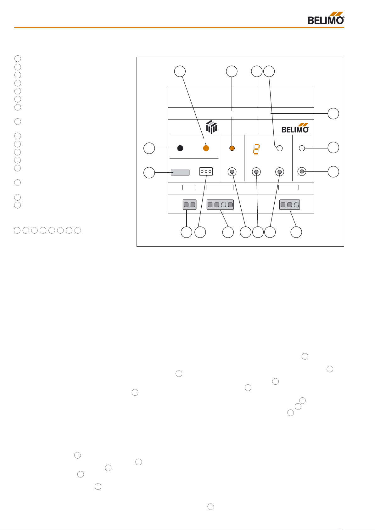
Power LED
Error LED
Test in progress LED
MP address display
Registered actuator LED
Individual Neuron ID
Status LED function according to
Echelon Guidelines
Service button for commissioning
with LONWORKS®
Unit power supply AC or DC 24 V
SET button for MP addressing
Up button for MP addresses
Start test button
MP connector: For connecting
MFT(2)/MP actuators
MFT-H connector: For connecting the
MFT parameterising tool
LONWORKS® connector
Node label
The operating controls numbered
are described below in greater detail.
Automatic scanning
of the MP network
As soon as the UK24LON unit is power-
ed up it starts scanning the MP network
automatically. All eight MP addresses are
interrogated cyclically to see whether the-
re is an actuator available to respond. The
results are compared against a reference
table stored in the UK24LON unit. If an ac-
tuator responds from an MP address that
is not assigned in the reference table it is
automatically inserted into the table.
If an actuator already assigned in the refer-
ence table fails to respond an error alarm
is initiated but the reference table is not
altered in any way. The actuators can be
pre-addressed so that they are recognis-
ed automatically when they are connect-
ed to the MP network.
Manual addressing
of actuators
● All required actuators must be connect-
ed first.
● Use the Up button to select the
address to be issued. The actual add-
ress will be shown on the display .
● Use the Set button to start the
addressing process (hold for at least
2 seconds). The Reg’d LED starts
flashing slowly (at 1⁄2 second intervals)
to indicate that the process is in pro-
gress.
● Within the next 10 minutes, the MFT(2)/
MP actuator being addressed must be
reset (in the case of standard damper
actuators by pressing the addressing
button; in the case of spring return ac-
tuators by moving the L/R switch back
and forth and in the case of globe valve
actuators by pressing the S2 button).
The UK24LON unit will then be able to
recognise and address the actuator.
This status is indicated by fast flashing
of the Reg’d LED .
● As soon as addressing of the actua-
tor has been completed the Reg’d LED
– gives a steady light. This also indi-
cates that the MP address has been
successfully stored in the reference ta-
ble of the UK24LON unit.
Notes on addressing
● If none of the actuators has been re-
set within 10 minutes of the addressing
process being initiated, the process will
be discontinued. The reference table re-
mains unchanged and the Reg’d LED
- stops flashing.
● If an address is issued that has already
been assigned to another actuator the
latter is automatically de-addressed first
before the new actuator is addressed.
●
If a mistake is made in initiating address-
ing, the process can be stopped by
briefly pressing the Set button .
● Normal data traffic on the MP network
is interrupted while addressing is in pro-
gress.
Manual de-addressing
of MFT(2)/MP actuators
● All actuators that are to be de-addressed
must be connected first.
● Press the Up button to select the
address to be deleted. The current
address is shown on the display .
● Start de-addressing by pressing the
Set button (min. 2 s). The Reg’d LED
flashes slowly as a check (every 1⁄2
second).
● Press the Set button a second time
until the Reg’d LED flashes rapidly.
● The Reg’d LED goes out after the
actuator has been de-addressed, i.e.
removed from the reference table and
set to the address "PP".
Operation, characteristics of the UK24LON unit
Power
Error
MFT - H
UK24-LON
Service
Made in Switzerland
Status
Node
IC-DZ.03
Test
Test in
Progress
Address
Select
Up
Set
Reg'd
MP-Com.
24V0V YU/MP
Power
n.c.
LonTalk
a b
24V0V
NID: XXXXXXXXXXXX
1
16
3
7
8
15
14
13 12 11
10
9
25
4
6
UK24LON
Legend for operating controls
10
11
12
13
14
15
16
11
4
10
5
5
5
11
4
10
10
5
5
5
5
1
2
3
4
5
6
7
2 3 4 5 7 10 11 12
8
9
ENG · 02.07· PDF · Subject to technical changes
b0291102
10
Operation, Characteristics

13
Connecting parameterising tools for the MFT(2)/MP actuators
(A ZIP interface USB/MP is also available)
Using the Belimo PC-Tool or the MFT-H
manual parameterising device it is very
easy to preset specific parameters (e.g.
running time) for individual actuators.
The MFT-H or the PC (PC via ZIP-RS232
interface) can be connected to the 3-pole
plug socket of the UK24LON unit to obtain
direct access to the appropriate actuator.
During access the UK24LON unit signals
that communication between MFT-H or
PC-Tool and actuator is in progress by
means of a letter H on the display .
4
ENG · 02.07· PDF · Subject to technical changes
Operation, Connecting parameterising tools
Notes on de-addressing
● If, after de-addressing has been initiat-
ed, the Set button is not pressed
a second time, the de-addressing pro-
cess will be discontinued. The reference
table remains unchanged and the Reg’d
LED stops flashing.
● If there is no actuator connected, only
the entry in the reference table of the
UK24LON unit will be deleted. It will be
registered again when the actuator is
reconnected.
● If a mistake is made in initiating de-
addressing, the process can be stop-
ped by pressing the Set button .
● Normal data traffic on the MP network
is interrupted while de-addressing is in
progress.
Testing the MFT(2)/MP actuators
● Use the Up button to select the
address to be tested. The actual address
will be shown on the display.
● Now start the test with the Test but-
ton . The Test in progress LED gg
gives a steady light to indicate that the
process is in progress. The actuator
opens fully and then closes fully.
● When the test has been completed the
Test in progress LED goes out and
the actuator returns to its last reference
position.
Notes on testing
● If a mistake is made in initiating test-
ing, the process cannot be stopped.
Normal data traffic with the other actua-
tors on the MP network is continued
while testing is in progress.
● Note: By holding the button depressed
for more than 2 seconds all addressed
and responding actuators can be tested
simultaneously.
● No mechanical testing of actuators can
be initiated at addresses that have either
not been registered or are incorrect.
Automatic standby mode
(darkening of the display)
The displays and operating controls of
the UK24LON unit are deactivated auto-
matically when they are not being used in
order to save energy and to avoid acci-
dental (mal-)operation.
Automatic deactivation occurs approxi-
mately 2 minutes after the last time an
operating control is used provided there is
no mechanical testing or addressing in pro-
gress and no errors are being displayed.
The unit can be reactivated by pressing
the Up button (for at least 2 s). It will
not be possible to perform a mechanical
actuator test or addressing/de-addressing
until this has been done.
Error displays
1. Permanently lit LED
The UK24LON unit can detect commu-
nications faults on the MP network. They
are indicated by the Error LED lighting
up and the appropriate address being dis-
played. If more than one address is af-
fected the lowest one will be displayed.
The display can then be scrolled with the
Up button .
The UK24LON unit cannot change to
standby mode as long as an error is being
displayed.
2. Flashing LED
A flashing LED Error and simultaneous
display of the MP addresses indicates a
mechanical fault of the corresponding
MFT(2)MP actuator. (The fault can be dia-
gnosed with the PC-Tool).
The flashing Error LED means that the
MP communication between UK24LON
and the corresponding actuator is OK.
LON status display
The Status LED behaves as indicated
in the Echelon Guidelines:
● Dark:
The UK24LON unit is ready for service
and connected to the LONWORKS® net-
work.
● Flashing at 2-second intervals:
The UK24LON unit is ready for service
but not connected to the LONWORKS®
network.
● Steady light:
The UK24LON unit has not been loaded
with application software.
● Other flashing:
There is a fault in the UK24LON unit.
10
10
11
12
11
5
2
7
311
3
2
Interface
converter
RS232 / MP
Main adapter
AC 230 / 24 V
AC 24 V
DC 24 V

14
Notes

15
Notes

ENG-01.07· PDF · Subject to technical changes
All-inclusive.
Belimo worldwide: www.belimo.com
5 year
warranty
On site around
the globe
A complete
range of products
from one source
Tested quality
Short delivery
times
Comprehensive
support
Headquarters
BELIMO Holding AG
Brunnenbachstrasse 1
CH-8340 Hinwil
Tel. +41 (0)43 843 61 11
Fax +41 (0)43 843 62 68
www.belimo.com
Subsidiaries, Representatives and Agencies
Argentina
Australia
Austria
Bahrain
Belgium
Bosnia-Herzegovina
Brazil
Bulgaria
Canada
Chile
Croatia
Cyprus
Czech Republic
Denmark
Egypt
Estonia
Finland
France
Great Britain
Germany
Greece
Hong Kong
Hungary
Iceland
India
Indonesia
Ireland
Israel
Italy
Japan
Jordan
Kuwait
Latvia
Lebanon
Liechtenstein
Lithuania
Luxembourg
Malaysia
Mexico
Morocco
Netherlands
New Zealand
Norway
Oman
Pakistan
People‘s Republic
of China
Philippines
Poland
Portugal
Qatar
Republic of Korea
(South Korea)
Rumania
Russia
Saudi Arabia
Singapore
Slovakia
Slovenia
South Africa
Spain
Sweden
Switzerland
Taiwan
Turkey
Ukraine
United Arab
Emirates
United States
of America
Table of contents
Other Belimo Gateway manuals


 user guide")

