List of Figures
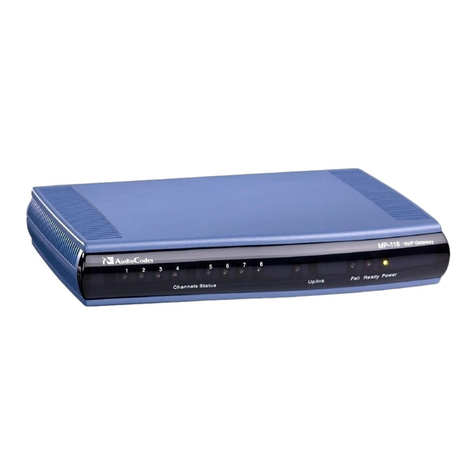
Figure 2-1: MP-11x Front Panel (e.g., MP-118)......................................................................................9
Figure 2-2: MP-11x Rear Panel (e.g., MP-118).....................................................................................10
Figure 2-3: MP-11x Underside...............................................................................................................11
Figure 2-4: 19-inch Rack Shelf for MP-11x ...........................................................................................12
Figure 2-5: MP-11x Rack Mount Installation .........................................................................................13
Figure 2-6: RJ-45 Connector Pinouts for Ethernet Connection.............................................................14
Figure 2-7: Connecting to the Ethernet .................................................................................................14
Figure 2-8: RJ-11 Connector Pinouts for FXS Interface........................................................................15
Figure 2-9: Connecting FXS Interfaces .................................................................................................15
Figure 2-10: RJ-11 Connector Pinouts for FXO Interface.....................................................................16
Figure 2-11: Connecting FXO Interfaces...............................................................................................16
Figure 2-12: RJ-11 Lifeline Splitter Connector Pinouts.........................................................................17
Figure 2-13: Lifeline Cabling (Using Splitter Cable) for FXS-Only Devices...........................................17
Figure 2-14: Lifeline Cabling for FXS and FXO Devices.......................................................................18
Figure 2-15: PS/2 to DB-9 Adaptor Connector Pinouts.........................................................................18
Figure 2-16: PS/2 Connector Pinouts....................................................................................................18
Figure 2-17: Connecting the Serial Port................................................................................................19
Figure 2-18: Connecting to the Power Supply.......................................................................................20
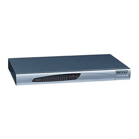
Figure 3-1: MP-124 Front Panel............................................................................................................21
Figure 3-2: Rear Panel of MP-124 AC Powered Model.........................................................................22
Figure 3-3: Rear Panel of MP-124 DC Powered Model ........................................................................22
Figure 3-4: MP-124 Desktop Mounting..................................................................................................24
Figure 3-5: MP-124 with Brackets for Rack Installation.........................................................................24
Figure 3-6: Grounding and Power Surge Protection .............................................................................28
Figure 3-7: RJ-45 Connector Pinouts for Ethernet Connection.............................................................29
Figure 3-8: Connecting to the Ethernet .................................................................................................29
Figure 3-9: 50-pin Telco Connector.......................................................................................................30
Figure 3-10: MP-124 in a 19-inch Rack with MDF Adaptor...................................................................31
Figure 3-11: MP-124 RS-232 Connector Pinouts..................................................................................32
Figure 3-12: MP-124 Serial Cabling ......................................................................................................32
Figure 3-13: AC Power Cabling.............................................................................................................33
Figure 3-14: Wired DC Power Terminal Block Connected to MP-124 ..................................................34
List of Tables
Table 1-1: MP-1xx Model Telephony Support.........................................................................................7
Table 2-1: MP-11x Front-Panel LEDs Description ..................................................................................9
Table 2-2: MP-11x Rear Panel Component Descriptions......................................................................10
Table 2-3: Mounting Components on MP-11x Underside .....................................................................11
Table 2-4: MP-11x Rack Mount.............................................................................................................13
Table 3-1: MP-124 Front-Panel LEDs Description................................................................................21
Table 3-2: MP-124 Rear-Panel Description...........................................................................................22
Table 3-3: MP-124 Rear-Panel Ethernet LEDs Description..................................................................23
Table 3-4: 50-pin Telco Connector Pin Allocations ...............................................................................30


