Bell System Master 200Plus User manual

18 September 2003 PD001 Iss 2
M200+ Software Version 1.4 - 1.5
C200+ Software Version 2.3, PCB Issue 2.1
Master 200Plus - Wardens Call System
Operators Manual
Bell System (Telephones) Ltd
Presley Way, Crownhill, Milton Keynes, MK8 0ET.

18 September 2003 PD001 Iss 2
- i -
Contents
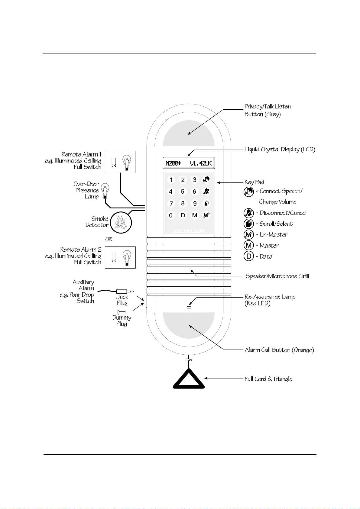
Diagram 1 - The M200+ Room Unit .....................................1
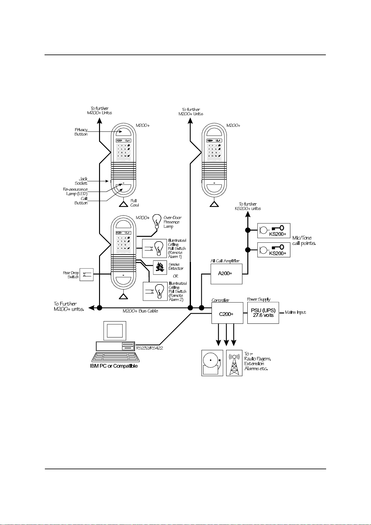
Diagram 2 - System Overview .........................................2
Master 200Plus System Overview ......................................3
M200+ Room Unit .............................................3
M200+ Accessories ............................................4
C200+ Controller ..............................................5
C200+ Accessories ............................................5
Other Peripherals ..............................................6
Power Supplies ...............................................6
Resident Mode .....................................................7
Privacy Button ................................................7
Making an Emergency Call (Alarm) ................................8
Operator Mode .....................................................9
Master and Monitor Mode .......................................9
Gaining Access to Master or Monitor Mode ..........................9
Converting a Monitor Station into a Master Station ...................12
Other Monitor Mode Messages ..................................12
Un-Mastering/Un-Monitoring a Unit ...............................13
Diagram 3 - Gaining Access to Master or Monitor Mode ...............14
Receiving Alarm Calls ...............................................15
No Activity ..................................................15
Alarm Calls Messages .........................................15
Establishing Speech With a Calling Unit ................................17
Volume Adjustment During Speech ...............................17
Cancelling an Alarm Call Following Speech (Master Cancel) ...........18
Cancelling an Alarm Call from the Calling Unit (Local Cancel) ..........18
Automatic Cancellation During Speech ............................19
Multiple Alarm Calls ...........................................19

18 September 2003 PD001 Iss 2
- ii -
Jack Socket/‘Pear Drop’ Switch Removal ..........................19
Alarm Priority .....................................................20
Smoke Detector (Fire) Alarms ...................................20
Call For Assistance ...........................................20
Diagram 4 - Handling a Typical Alarm ..................................21
Calling a Room Unit ................................................22
Calling Up a Room Unit (Numeric Flat Number) .....................22
Calling Up a Room Unit (Alpha Numeric Flat Number) ................23
Calling Up a Room Units with the Same Number ....................24
Speech Operation ............................................26
Annunciation Tone ............................................26
Privacy Operation ............................................26
Invalid Flat Number ...........................................27
Self-Diagnostic Messages ...........................................28
Power-up/Reset Message ......................................28
Fault Codes .................................................28

18 September 2003 PD001 Iss 2
- 1 -
Diagram 1 - The M200+ Room Unit

18 September 2003 PD001 Iss 2
- 2 -
Diagram 2 - System Overview

18 September 2003 PD001 Iss 2
- 3 -
Master 200Plus System Overview
The Master 200Plus (M200+) system is an emergency alarm and communication
system intended for sheltered housing and nursing homes. The system consists of up
to 250 identical M200+ Room Units positioned in each dwelling, in communal rooms
and in staff flats and offices.
M200+ Room Unit
Each M200+ room unit serves as a call-point from which the residents may make an
alarmcall,usingtheintegralcall-button,pull-cordorotherexternalalarmswitch/device
(see M200+ accessories listed below).
Inaddition eachRoom Unithas akeypad anddisplay foruse bythe WardenorNursing
staff; Any unit may therefore be used to monitor alarm calls, to establish speech
communication with the residents and to perform various other control functions.
The Room Unit can be programmed to display messages in many languages, these
include English, German, French, Dutch, Spanish, Swedish and Italian.

18 September 2003 PD001 Iss 2
- 4 -
M200+ Accessories
Ceiling Pull Switch (Illuminated):One or more of these remote switches may be
connected to the Room Unit to enable an alarm call to be made from various positions
within a flat. The optional illumination is provided to reassure the resident that the call
has been registered by the system.
Jack-Socket:This enables a pear-drop switch or similar device to be plugged into the
side of the M200+ room unit. This may be removed when not required either by
replacingit withthedummy plug(supplied) orbydisabling thefeature byprogramming.
Smoke Detector:A suitable smoke detector may connected to the ‘Smoke Detector’
input of the room unit. A high priority alarm call is generated if the smoke detector is
triggered.
Remote Alarm 2: One or more of these remote switches may be connected to the
Room Unit to enable an alarm call to be made from various positions within a flat. The
optional illumination is provided to reassure the resident that the call has been
registered by the system. This type of alarm is only avaliable if the smoke detector is
not needed.
Presence Lamp:This lamp is normally fitted outside the room, above the door and
signals the presence of a member of staff in that room.

18 September 2003 PD001 Iss 2
- 5 -
C200+ Controller
IneachM200+systemasingleC200+controllerisrequiredtoco-ordinatetheoperation
of the M200+ room units and other equipment. This would normally be located in the
electrical cupboard.
C200+ Accessories
Extension Alarms/Pagers:Any device such as an audible alarm or flashing lamp or
radio pager transmitter, which can alert the staff when an alarm call has been made,
maybe directly connectedto the C200+ controller.Each of the3 Alarm outputsmay be
programmedto operate upon anypermutation of alarm types (e.g. All alarm types; Fire
alarm only).
Personal Computer:During installation, the controller may be connected to an IBM
orcompatiblePC(desktoporlaptop)viaanRS232orRS422cable,inordertoprogram
the system with several custom parameters (e.g. the list of valid flat numbers).
GroupMaster 200+ Software:This is a Microsoft®Windows®software package
designedtobe usedwitha PC. The GroupMaster200+software enablesseveralextra
features that include;
CThe ability to group individual systems to form one or more larger systems.
CThe display of all system activities (on the screen) including alarm calls, Master
and Monitor stations.
CActivation of intelligent radio pagers with appropriate messages.
CThe logging of all system activities either to a printer or to a computer file.
For further information refer to the GroupMaster 200+ operators manual.

18 September 2003 PD001 Iss 2
- 6 -
Other Peripherals
AllCall Amplifier:The AllCall Amplifier (A200+) is used to generate an emergency
alarm tone in all M200+ Room Units simultaneously (e.g. to evacuate the building) or
tomakeageneralannouncement.OneormoreKS200+unitarerequired.TheKS200+
unit contains a microphone and tone generator, either of which may be activated by a
keyswitch.
D200+ Auto-Dialer: The D200+ communicator in conjunction with the Scantronic
Homelink Extra is designed to interface a M200+ Wardens Call System to an off-site
central monitoring station via the public telephone network (PSTN). When active all
alarm calls are routed to the central monitoring station, where staff can converse with
theresident and determine the necessarycourse of action. Forfurther informationsee
the D200+ Auto-Dialler Installation/Operators Manual.
Door Entry Panel: The Door Entry Panel provides a means of connecting a door
entrancepanel(atthebuildingentrance)toanM200+WardenCallSystem. Forfurther
information see the DEP200+ Door Panel Installation Manual.
GPI200+: The GPI200+ General Purpose Interface provides an economic means of
connectingupto eight pull-cordswitches orother devices ontoan M200+Wardens Call
System,insituationswherespeechcommunicationisnotrequired,e.gbathrooms. For
further information see the GPI200+ Installation/Operators Manual.
Power Supplies
The M200+ system power supply should be an uninterruptable power supply (UPS);
that is, if the mains power fails the unit should continue to work on internal batteries.

18 September 2003 PD001 Iss 2
- 7 -
Resident Mode
Normally the M200+ room unit is said to be in 'RESIDENT MODE'. In this mode the
keypad is disabled so that the resident need only use the CALL button, PULL-CORD,
any remote switches or the PRIVACY button.
Privacy Button
The M200+ room unit display in 'RESIDENT MODE' has only 2 conditions; blank or the
following message:
PRIVATE
This message may be toggled on or off by pressing the PRIVACY button (The grey
button at the top of the unit).
When the display shows ‘PRIVATE’the resident cannot be listened in to unless they
have made an alarm call. If the privacy button is pressed during speech the effect is
only temporary, returning to the previous setting when speech is finished.
The privacy button has several programmable options;
i. ‘Permanently On’ (the privacy button has no effect except during speech)
ii. ‘Permanently Off’ (the privacy button has no effect)
iii. Default to on. The unit will start in the ‘Privacy On’ state, (display ‘PRIVATE’) in
the event of a restart or power failure.
iv. Default to off. The unit will start in the ‘Privacy Off’ state, (display blank) in the
event of a restart or power failure.
Refer to the Installation Manual for details on programming the privacy options.

18 September 2003 PD001 Iss 2
- 8 -
Making an Emergency Call (Alarm)
An alarm call may be initiated at each M200+ room unit by one of the following
methods:-
a) Operation of the Call Button (Orange button at the bottom of the unit).
b) Operation of the Pull-Cord at the bottom of the M200+ unit (if fitted).
d) Operation of the Remote Switch e.g. Illuminated ceiling pull switch.
e) Activation of the Smoke Detector.
c) Operation of the 'Pear-drop switch' or other device which is plugged into the
jack-socket (or by inadvertent removal of the jack plug)
In each case the M200+ room unit will illuminate the Re-Assurance Lamp (Red LED)
and illuminated ceiling pull-switches (if present).
The staff are alerted to alarms by:-
a) Any room unit enabled as a Master/Monitor sounding an alarm tone, (provided
the unit is programmed to do so).
b) Extension alarms, such as an audible alarm or flashing lamp (if present).
c) A radio pager (if available).
Avariety of alarm tone sounds may be programmed for each alarm type, e.g. the fire
alarm could be set to a continuous tone and the pull cord set to an intermittent warble.
Refer to the Installation Manual for full details of how to set the alarm tones.

18 September 2003 PD001 Iss 2
- 9 -
Operator Mode
Master and Monitor Mode
Asystem operator can place any room unit in Master or Monitor mode, in order to
receive and/or initiate an alarm call. In both modes the LCD display becomes active
and will display details of received alarm calls.
Master mode In Master mode the operator is able to answer alarm calls and to
initiate calls, by using the keypad. In order to prevent conflicting
commands from several operators, only one room unit at a time can
be in Master mode.
Monitor mode In most cases Master and Monitor mode are indistinguishable to the
operator. Whenever keypad commands are made on a Monitor
mode room unit, the system will automatically upgrade the room unit
to Master mode in order to carry out the command. Only if the
current Master is in use at the time (ie locked) will this action be
inhibited. AMasterbecomeslocked,wheneverspeechisinprogress
and also for a short period of time immediately after the unit was
made a Master.
There is no limit to the number of Monitor units on a system, however, a maximum of
4(including the Master unit) can sound an alarm tone simultaneously, fitting an A200+
(AllCall Amplifier) avoids this limit (see installation manual).
In Master and Monitor mode the over-door presence lamp (if fitted) will be illuminated.
Gaining Access to Master or Monitor Mode
In order to gain access to operator functions the operator must make use of one of the
M200+ units and enable it as a Master or Monitor. This can be accomplished by
pressing the mkey and then, if required, typing an access code (this can be 1 to 4
digits). Theaccesscodemay bechangedasrequired (refer totheInstallationManual)

18 September 2003 PD001 Iss 2
- 10 -
Proceed as follows:-
Display
Press mENTER CODE ____
Display
Type 1234 ENTER CODE *___
(or other access code)
ENTER CODE **__
ENTER CODE ***_
Display (momentarily)
Waiting for response >

18 September 2003 PD001 Iss 2
- 11 -
Display for 2 seconds
If no other station is a Master MASTER
(Indicates Master access granted)
Display for 2 seconds
Or there is currently a Master station. MASTER AT 12A
(Indicates Master access not
granted; Unit in Monitor mode)
Display
No Calls
(Message may vary with
circumstances)
See also Diagram 3 - Gaining Access to Master or Monitor Mode.

18 September 2003 PD001 Iss 2
- 12 -
Converting a Monitor Station into a Master Station
If the operator requires Master status the mkey may be pressed, in order to take
control. The system will then make this unit the new Master providing the current
Master station is unlocked;A locked Master station is one which is either engaged in
speech or has recently been made a Master, (duration is programmable). A Monitor
station with a locked Master will display
12A isthecurrent lockedMasterstation.Master at 12a
Pressing other function keys such as *(connect Speech) will automatically make a
unit a Master (unless the current Master is locked) in order to carry out that function.
Other Monitor Mode Messages
IfanattemptismadetobecomeaMasterwheneithertheAllCallamplifierorthecentral
monitoring station is in use one of the following messages will be seen.
AllCall Amplifier in useAll Call Active
System switched to central monitoring station.Central active
When these devices are in use it is not possible to make a unit a Master station without
first disabling them.

18 September 2003 PD001 Iss 2
- 13 -
Un-Mastering/Un-Monitoring a Unit
It is important that when a unit is no longer required as a Master or Monitor it be
returned to 'RESIDENT MODE' (Otherwise it may be impossible for the resident to
make an alarm call); this is done by pressing the ukey.
It is also possible for a room unit to be programmed to remain in Master/Monitor mode
for a limited time period. Refer to the Installation Manual for details.

18 September 2003 PD001 Iss 2
- 14 -
Diagram 3 - Gaining Access to Master or Monitor Mode

18 September 2003 PD001 Iss 2
- 15 -
Receiving Alarm Calls
AnyM200+roomunitenabled as aMasterorMonitorstationwill alwaysdisplaysystem
activity such as pending alarm calls. Refer to Diagram 4 - Handling a Typical Alarm.
No Activity
If there is currently no activity on the system the display will show:
NO CALLS
Alarm Calls Messages
If there is an alarm call the Master station and Monitor stations will display the flat
number as well as the Alarm type as follows:
- Call button or pull cord alarm at flat 2020.ALARM 2020
- Remote switch (ceiling pull switch) alarm at flatALARM REM. 12A
12A.
- Auxiliary switch (Jack socket) e.g. 'Pear DropALARM AUX. 101
Switch' alarm at flat 101.
- Remote switch alarm in the bedroom of flat 157.ALARM BED. 157
- Remote switch 2 alarm at flat 46.ALARM REM2. 46

18 September 2003 PD001 Iss 2
- 16 -
- Remote switch alarm in the bathroom of flatALARM BATH. 57B
57B.
- Smoke detector alarm at flat 10.FIRE ALARM 10
- Call for assistance alarm at flat G2.HELP AT G2

18 September 2003 PD001 Iss 2
- 17 -
Establishing Speech With a Calling Unit
To enable speech with the displayed room unit number, press the *button on the
keypad. The operator may then speak with the resident by pressing and holding the
'Privacy button' (grey button at top of the unit) and listen by releasing the button.
During speech one of the following display messages will be seen:
Speech with flat 12A; Volume low.SPEECH LO 12A
Speech with flat 12A: Volume high.SPEECH HI 12A
If there are additional alarm calls waiting to be dealt with the flat number and
re-assurance lamp (red LED) will flash.
Volume Adjustment During Speech
When a resident makes an alarm call he or she may be positioned close to the room
unit or a distance away. To allow for this, the M200+ system has a High and Low
volume level for received speech. The operator may change the volume level during
speech by alternately pressing the *button. The initial volume level may be preset
for each alarm type (refer to the Installation manual).
The Master unit microphone is always set at low volume because the operator will
always be close to the unit.
Table of contents
Popular Emergency Phone manuals by other brands

Climax
Climax Call Point CP-23 user manual

RATH MICROTECH
RATH MICROTECH SMARTPHONE III Simplified Programming Instructions

Hubbell
Hubbell GAI-TRONICS 293-101 manual

Viking
Viking BLK-3-EWP Technical practice

Soundoff Signal
Soundoff Signal Armada A300 quick start guide

Rath
Rath 2100-CD9 Installation & operation manual