Hubbell GAI-TRONICS 293-101 User manual

Pub. 42004-378A
GAI-Tronics Corporation P.O. Box 1060, Reading, PA 19607-1060 USA
610-777-1374 800-492-1212 Fax: 610-796-5954
VISIT WWW.GAI-TRONICS.COM FOR PRODUCT LITERATURE AND MANUALS
GAI-TRONICS® CORPORATION
A HUBBELL COMPANY
Model 293-101, 293-101AL, 297-101,
298-101, and 294-101AL Auxiliary Powered
Emergency Phones
TABLE OF CONTENTS
Getting Started ................................................................................................................................1
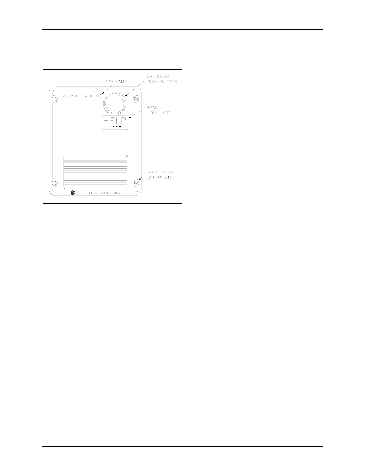
Product Overview ...................................................................................................................................1
Standard Operation................................................................................................................................3
Placing an Emergency Call...................................................................................................................................3
Placing a Non-Emergency Call (Models 294-101AL and 298-101 Only)............................................................3
Americans with Disabilities Act (ADA) Functionality.........................................................................4
Installation ......................................................................................................................................5
Safety Guidelines.....................................................................................................................................5
General Installation Guidelines.............................................................................................................5
Tamper-Resistant Hardware .................................................................................................................................5
Conduit Installation Details ..................................................................................................................................6
Models 293-101, 293-101AL, and 294-101AL.......................................................................................7
Models 297-101 and 298-101..................................................................................................................9
Setup..............................................................................................................................................12
Hardware Configuration......................................................................................................................12
Audio Level Adjustments.....................................................................................................................14
Programming ................................................................................................................................15
Remote Programming ..........................................................................................................................15
Local Programming..............................................................................................................................16
Programming Sequences......................................................................................................................18
Dialing Options...................................................................................................................................................18
Password.............................................................................................................................................................20
Silent Monitoring Feature...................................................................................................................................20
Off-Hook Ringing...............................................................................................................................................20
Disconnect Options.............................................................................................................................................21
Americans with Disabilities Act (ADA) Programming......................................................................................22
Maintenance..................................................................................................................................24
Specifications ................................................................................................................................25

PUB. 42004-378A
GAI-Tronics Corporation P.O. Box 1060, Reading, PA 19607-1060 USA
610-777-1374 800-492-1212 Fax: 610-796-5954
VISIT WWW.GAI-TRONICS.COM FOR PRODUCT LITERATURE AND MANUALS
Model 293-101, 293-101AL, 297-101,
298-101, and 294-101AL Auxiliary Powered
Emergency Phones
Getting Started
Product Overview
Thank-you for your purchase of a GAI-Tronics ADA-compliant emergency telephone. This manual
applies to the following GAI-Tronics ADA-Compliant Emergency Telephones:
Model Description
293-101 Emergency Phone – This phone is housed in a safety yellow, glass-reinforced polyester
enclosure that is designed to be surface-mounted and includes an emergency push button.
293-101AL Emergency Phone – The vandal-resistant phone is housed in a cast aluminum enclosure
painted safety yellow that is designed to be surface-mounted and includes an emergency
push button.
294-101AL Emergency Phone with Keypad – A cast aluminum enclosure painted safety yellow that
is designed to be surface-mounted and includes a 12-button Braille keypad, an emergency
push button and a call (off-hook) button.
297-101 Flush-panel Emergency Phone – This is a flush-mount phone with a heavy-gauge
brushed stainless steel front panel, and includes an emergency push button.
298-101 Flush-panel Emergency Phone with Keypad – This flush-mount phone with a heavy-
gauge brushed stainless steel front panel includes a 12-button Braille keypad, an
emergency push button, and a call (off-hook) button.
All of the emergency telephones listed above comply with the Americans with Disabilities Act (ADA).
Each phone includes a Braille tag for vision-impaired individuals to identify the functions of the
telephone and a visual indication for hearing-impaired individuals indicating that an emergency call has
been answered.
The CALL RECEIVED WHEN LIT LED is the visual call-received indicator. When the security officer
answers the telephone and acknowledges the call, the LED will light. The LED remains lit until the call
is disconnected.

PAGE 2of 28
AUXILIARY POWERED ADA-COMPLIANT EMERGENCY PHONES Pub. 42004-378A
d:\standard ioms - current release\42004 instr. manuals\42004-378a.doc
05/06
The GAI-Tronics emergency phone product line provides the flexibility to address a diverse range of
applications. A wide variety of functions can be achieved by altering the configuration data stored in the
phone’s non-volatile memory. These configuration options include:
•Pre-programmed auto-dial telephone numbers
•Call termination method (automatic or manual)
•Maximum call duration
•Answering options
Each of the above emergency phones require a “Class 2” 12 V dc regulated power supply (included) and
can be connected to any of the following:
•Central Office (CO) line to the Public Switched Telephone Network (PSTN)
•24 V dc or 48 V dc analog station port of Private Branch Exchange (PBX), Private Automatic Branch
Exchange (PABX) or KSU.
Connection may not be made to pay phone extensions or shared service (party) lines.
NOTE:Each telephone requires a dedicated power supply. Multiple telephones cannot be
connected to a single power supply. The power supply must provide galvanic isolation between its
input and its 12 V dc output. For dc-to-dc applications, galvanic isolation is required. Galvanic
isolation (separation) is achieved by using a transformer or opto-coupler.

PAGE 3of 28
AUXILIARY POWERED ADA-COMPLIANT EMERGENCY PHONES Pub. 42004-378A
d:\standard ioms - current release\42004 instr. manuals\42004-378a.doc
05/06
Standard Operation
Placing an Emergency Call
1. Press the EMERGENCY push button to place an immediate call to a preprogrammed emergency
number, typically a security office or 911.
2. The emergency operator lifts the handset, and presses *to acknowledge the call.
3. Once acknowledged, the CALL RECEIVED WHEN LIT lamp on the phone’s front panel illuminates, and
communication can begin.
Placing a Non-Emergency Call (Models 294-101AL and 298-101 Only)
The emergency phone models with keypads can also be used to make non-emergency type calls as
follows:
1. Press the CALL push button.
2. Wait for dial tone.
3. Use the keypad to dial the desired number.
To disconnect the call, press the CALL push button a second time.

PAGE 4of 28
AUXILIARY POWERED ADA-COMPLIANT EMERGENCY PHONES Pub. 42004-378A
d:\standard ioms - current release\42004 instr. manuals\42004-378a.doc
05/06
Americans with Disabilities Act (ADA) Functionality
Call Received Indicator Lamp
The CALL RECEIVED WHEN LIT lamp indicates to hearing-impaired individuals that the emergency call
has been answered. When the individual presses the emergency push button, the person receiving the call
(typically the security operator) presses the * DTMF button. The telephone detects the * DTMF signal
and illuminates the CALL RECEIVED WHEN LIT lamp.
Location Identification Code Dialing
The Location Identification Code feature enables security personnel to quickly and easily locate an
individual in trouble. When the individual presses the EMERGENCY push button, the person receiving the
call (typically the security operator) presses the * DTMF button. The telephone detects the * DTMF
signal and transmits a three-digit location identification code to identify which emergency telephone is
originating the call. This location code can be displayed on a DTMF decoder device (not supplied).
Disconnecting Calls
There are both manual and automatic methods included in the emergency telephones to disconnect calls.
The disconnect methods include the following:
•To remotely disconnect an emergency call, operator presses the #for a least 2 seconds or # # twice
within 2 seconds.
•To manually disconnect an emergency call, press the EMERGENCY button after 15 seconds (can be
disabled).
•To manually disconnect a non-emergency call, press the CALL button a second time.
•To automatically disconnect;
-All calls, loop current disconnect.
-All calls, maximum call duration timeout (configurable from 1 minute to 99 minutes) or disable for
no timeout.
-Emergency and incoming calls, call progress tones (dial tone, busy signal, fast busy (or reorder)
tone)
For factory defaults and available options, please refer to the Programming section of this manual
beginning on page 15.

PAGE 5of 28
AUXILIARY POWERED ADA-COMPLIANT EMERGENCY PHONES Pub. 42004-378A
d:\standard ioms - current release\42004 instr. manuals\42004-378a.doc
05/06
Installation
ATTENTION Installation should be performed by qualified personnel and only in
accordance with the National Electrical Code or applicable local codes.
Safety Guidelines
When installing any GAI-Tronics telephone equipment, please adhere to the following guidelines to
ensure the safety of all personnel:
•Do not install telephone wiring during a lightning storm.
•All telephone models must be properly connected to earth ground to protect personnel and to
minimize the effects of any electrostatic discharge (e.g., lightning). The Model 293-101AL, 294-
101AL, 297-101, and 298-101 Telephones each include a ground terminal. Please note proper
grounding does not eliminate the need for lightning protection for the telephone or the telephone
system.
•An additional UL Listed lightning arrestor may be installed on any phone or phone cable that is
exposed to a higher risk of lightning strikes. The lightning arrestor must be installed as close to the
phone as possible to maximize the protection. It must not be installed within the enclosure supplied
with the phone. Please consult our Service Center at 800-492-1212 for further information.
•Do not install telephone jacks in wet locations unless the jack is specifically designed for wet
locations.
•Do not touch uninsulated telephone wires or terminals unless the telephone line has been
disconnected at the network interface.
•If an ac source is available within five feet of the telephone, the included power supply can be used
The ac source and power supply must be mounted in a dry location, such as a GAI-Tronics stanchion.
•If the ac source is located more than five feet from the telephone either extend the wiring of the
included power supply, or provide a UL LISTED “Class 2” 12 volt dc regulated power supply.
Additionally, if the ac source is not located within the same structure or building, lightning/surge
protection is required.
General Installation Guidelines
GAI-Tronics emergency phones are designed to operate on telephone lines as detailed in the Product
Overview section of this manual. The telephones are designed to operate with one telephone per line. If
telephones are operated in parallel or “party line configuration” you may experience sporadic phone
operation, difficulties with programming, or premature disconnection of calls. Additionally, if special
features, e.g. voice mail, call waiting, etc, are not disabled, the phone may not function.
Tamper-Resistant Hardware
All of the telephones described in this manual are vandal resistant. The front panel for each telephone
covered in this manual is attached to its enclosure with tamper-resistant screws. A GAI-Tronics Model
233-001 Tamper-Resistant Screwdriver (sold separately) is recommended for installing the tamper-
resistant screws.

PAGE 6of 28
AUXILIARY POWERED ADA-COMPLIANT EMERGENCY PHONES Pub. 42004-378A
d:\standard ioms - current release\42004 instr. manuals\42004-378a.doc
05/06
Conduit Installation Details
GAI-Tronics recommends installing telephone lines in conduit to protect against accidental damage and
vandalism. To prevent moisture from entering the enclosure, we strongly recommend the following:
•Conduit should enter the enclosure from the bottom.
•Sealed fittings should be installed at all cable entry points.
•Silicone sealant or equivalent should be applied around and inside all conduit entries.
Please refer to the examples below for the recommended conduit installation details.
Figure 1. Bottom entry conduit recommended for
non-metallic enclosures Figure 2. Top entry conduit installation for non-
metallic enclosures (NOT recommended)
Figure 3. Bottom entry conduit installation details
for metallic enclosures Figure 4. Top entry conduit installation details for
metallic enclosures (NOT recommended)

PAGE 7of 28
AUXILIARY POWERED ADA-COMPLIANT EMERGENCY PHONES Pub. 42004-378A
d:\standard ioms - current release\42004 instr. manuals\42004-378a.doc
05/06
Models 293-101, 293-101AL, and 294-101AL
The mounting and wiring instructions for Models 293-101, 293-101AL and 294-101AL are as follows:
1. Remove the four tamper-resistant screws from
the front panel.
2. Position the enclosure on the mounting
surface. The enclosure provides four
0.28-inch mounting holes. Secure it with the
four ¼-inch diameter bolts of the appropriate
length for the mounting surface.
NOTE:When using the GAI-Tronics Model
231 Pole Mounting Kit, follow the mounting
instructions provided in the kit.
3. For Model 293-101 only: Create an access
hole using a Greenlee-type punch that is
equivalent in size to the conduit diameter.
Bottom entry is strongly recommended. Insert
a conduit fitting in the access hole. Refer to
conduit installation details on page 6.
NOTE:Use silicone sealant or equivalent
around and inside all conduit entries.
4. Pull the telephone line and power supply cord through the conduit.
5. Connect the power supply 4-pin connector to the P17 header jack on the PCBA.
6. Connect the telephone’s modular plug to a USOC RJ11 or CA11A (Canada) modular jack.
NOTE:A modular jack may be mounted inside the telephone. Connecting the telephone line directly
to TB1 is acceptable.
7. Perform the initial programming of the phone. Refer to the Programming section on page 15.
8. Make hardware configuration changes, if necessary. Refer to page 12 for more information. Verify
the phone is operating properly by calling to and from another phone.
9. Adjust the speaker levels if necessary. See the Audio Level Adjustments section on page 14 for
details.
10. Complete the installation by attaching the front panel assembly to the rear enclosure using the four
tamper-resistant screws.
Figure 5. Model 293-101 Emergency Phone in a
Non-metallic Enclosure

PAGE 8of 28
AUXILIARY POWERED ADA-COMPLIANT EMERGENCY PHONES Pub. 42004-378A
d:\standard ioms - current release\42004 instr. manuals\42004-378a.doc
05/06
Figure 6. Model 293-101AL Figure 7. Model 294-101AL
Figure 8. Model 293-101, 293-101AL, and 294-101AL Component Locations

PAGE 9of 28
AUXILIARY POWERED ADA-COMPLIANT EMERGENCY PHONES Pub. 42004-378A
d:\standard ioms - current release\42004 instr. manuals\42004-378a.doc
05/06
Models 297-101 and 298-101
Figure 9. Model 297-101 Figure 10. Model 298-101
Stanchion or Flush-mount Applications
1. When mounting in a GAI-Tronics Model 234 Series Stanchion or for flush-mount installations, the
supplied back box must be used to mount the Model 297-101 or 298-101 Telephone. Mount the back
box to the structure using the appropriate hardware. Refer to Figure 11 cutout dimensions.
2. If mounted outdoors, the installation of a telephone line suppressor (customer-supplied) on the
telephone line is recommended.
3. Remove the tapered plug from the top or bottom cable entry hole in the back box, and pull the
telephone line and power supply cord through.
4. Connect the power supply 4-pin connector to the P17 header jack on the PCBA.
5. Connect the telephone’s modular plug to a USOC RJ11 or CA11A (Canada) modular connector or (if
applicable) the telephone line suppressor. Refer to Figure 8 for the Model 297-101 and 298-101
component locations. Telephone line connections directly to TB1 are acceptable.
6. Perform the initial programming of the phone. Refer to the Programming section on page 15.
7. Make hardware configuration changes, if necessary. Refer to page 12 for more information. Verify
the phone is operating properly by calling to and from another phone.
8. Adjust the speaker levels if necessary. Refer to the Audio Level Adjustments section on page 14.
9. Attach the telephone’s front panel to the mounting flanges of the back box using the six supplied
#10-32 tamper-resistant screws and washers.

PAGE 10 of 28
AUXILIARY POWERED ADA-COMPLIANT EMERGENCY PHONES Pub. 42004-378A
d:\standard ioms - current release\42004 instr. manuals\42004-378a.doc
05/06
Figure 11. Model 297-101 and 298-101 Mounting Details

PAGE 11 of 28
AUXILIARY POWERED ADA-COMPLIANT EMERGENCY PHONES Pub. 42004-378A
d:\standard ioms - current release\42004 instr. manuals\42004-378a.doc
05/06
Figure 12. Model 297-101 and 298-101 Component Locations
(shown with connection to optional GAI-Tronics 530FB/531A Beacon)
Connecting a Beacon
Figure 12 above shows a typical connection detail of the GAI-Tronics 530FB/531A Beacon (sold
separately).

PAGE 12 of 28
AUXILIARY POWERED ADA-COMPLIANT EMERGENCY PHONES Pub. 42004-378A
d:\standard ioms - current release\42004 instr. manuals\42004-378a.doc
05/06
Setup
Hardware Configuration
The hardware options are explained in the following sections and the necessary jumper settings are
identified to enable or disable each option. We recommend reading the following sections, recording the
desired parameters and then making the necessary changes. The User Settings column in the Hardware
Settings Table on page 23 is provided for you to record your settings. The following options are
controlled by specific hardware configurations. See Figure 13 for the jumper locations.
Auto-answer Configuration
Factory Setting: Auto-answer feature enabled
The Auto-answer feature enables or disables the automatic answering of an incoming call. When the
Auto-answer feature is enabled, the phone automatically answers the call. When this feature is disabled,
the emergency telephone’s call button must be pressed to answer the call.
Enable: Insert the J14 jumper on pins 2 and 3.
Disable: Insert the J14 jumper on pins 1 and 2 (Do not use this setting except under the direction of
GAI-Tronics personnel.)
NOTE:The Auto-answer feature must be enabled during remote programming.
Polarity Configuration
Factory Setting: Non-polarity sensitive
This telephone can be configured to be polarity or non-polarity sensitive. When using the non-polarized
setting, the telephone operates with the telephone line’s positive terminal connected to either the tip or the
ring. When using the polarized setting, the telephone only operates with the telephone line’s positive
terminal connected to the tip. Use the Polarity Sensitive setting to allow a line voltage reversal disconnect
signal to disconnect the call.
Non-polarity Sensitive: Insert the J6 jumper on pins 2 and 3.
Polarity Sensitive: Insert the J6 jumper on pins 1 and 2.
Password Enable/Disable Configuration
Factory Setting: Enabled
This telephone can be configured to enable or disable the password protection for programming. This can
be useful when initially programming the telephones. Please see the Programming section of this manual.
Password Enabled: Insert a jumper on pins 2 and 3 of J9.
Password Disabled: Insert a jumper on pins 1 and 2 of J9.

PAGE 13 of 28
AUXILIARY POWERED ADA-COMPLIANT EMERGENCY PHONES Pub. 42004-378A
d:\standard ioms - current release\42004 instr. manuals\42004-378a.doc
05/06
Auxiliary Output
Each telephone includes one isolated solid state output capable of switching a maximum of 48 V dc, 125
mA or 28 VRMS ac, 80RMS mA. TB2 (OUT1) on the emergency phone PCBA provides the connections for
the auxiliary output. Refer to Figure 13 for the location of TB2.
The auxiliary output allows peripheral equipment, such as beacons, video cameras, and alarm generators,
to be activated when the EMERGENCY push button is pressed. The relay remains energized for the
duration of the emergency call.
In many applications, the auxiliary output is used to operate a GAI-Tronics Model 530FB/531A Beacon
(sold separately). For connection details, please refer to the Model 530FB/531A installation bulletin
included with the beacon. Information is also available at www.gai-tronics.com.
Figure 13. Emergency Phone PCBA

PAGE 14 of 28
AUXILIARY POWERED ADA-COMPLIANT EMERGENCY PHONES Pub. 42004-378A
d:\standard ioms - current release\42004 instr. manuals\42004-378a.doc
05/06
Audio Level Adjustments
Speaker Volume Adjustments
The speaker volume and microphone sensitivity are factory set to nominal levels that are acceptable for
most installations. However, some installations may require adjustments for the speaker and microphone.
Both the speaker and microphone adjustments are made using potentiometers on the emergency phone
PCBA. R106 is the speaker volume adjustment, and R88 is the microphone sensitivity adjustment.
Please refer to Figure 13 for the potentiometer locations.
Special care must be given to adjusting the speaker volume and microphone level. If one or both of the
levels are set too high, acoustic feedback (howling) can occur. If acoustic feedback occurs, we
recommend returning both potentiometers to the nominal factory settings and beginning the adjustment
again from this point.
Additionally, the acoustical characteristics of the emergency phones are different both when the front
panel is removed from the enclosure and when the front panel is tightly mounted in the enclosure. After
making any volume adjustments, we recommend mounting the front panel to the enclosure and again
testing the phone.

PAGE 15 of 28
AUXILIARY POWERED ADA-COMPLIANT EMERGENCY PHONES Pub. 42004-378A
d:\standard ioms - current release\42004 instr. manuals\42004-378a.doc
05/06
Programming
The telephone can be programmed remotely from a telephone, or locally at the telephone. To program
the Model 294-101AL and Model 298-101 locally, the front panel keypad can be used. However, to
program the 293-101, 293-101AL, and 297-101 models locally, a Model 51035-011 Keypad must be
connected to J13 on the telephone PCBA using the Model 51504-048 Keypad Cable Assembly. Refer to
Figure 8. See the Local Programming section on page 16.
For remote programming, a touch-tone (DTMF) telephone connected to a separate central office (CO) or
private branch exchange (PBX) line is required. Use a handset phone for remote programming the phone.
If a speakerphone is used, background noise can lead to incorrect settings. Do not use a cell phone. See
the Remote Programming section below.
Remote Programming
The programming mode is accessed by dialing a four-digit programming password. Should it become
necessary to bypass the password protection feature, see the Password Disabled Programming section on
page 16.
Password Enabled Programming
1. Enable the password protection feature—insert the J9 jumper on pins 2 and 3.
2. Enable the auto-answer feature—insert the J14 jumper on pins 2 and 3.
3. Using a touch-tone telephone, call the emergency telephone. (Do not use a cell phone.) The
emergency telephone automatically answers the call and generates a splash tone followed by a
success tone (single beep).
4. Dial the four-digit password. If the password has not been altered, dial 2468 (factory setting).
Otherwise, dial the preprogrammed user password. A success tone (single beep) is generated to
indicate the programming mode has been accessed.
NOTES:
•The telephone automatically times-out if 20 seconds elapse between digit entries, or if an invalid
password is entered.
•If DTMF digits have not been dialed within three seconds of the call initiation, the telephone
remains off-hook and the programming mode is terminated.
•If the success tone is not generated, the telephone has failed to recognize the password.
Therefore, the telephone must then be programmed with the password disabled. See the
Password Disabled Programming section on page 16.
5. If the success tone has been generated, begin entering the desired user-programmable parameters.
See the Programming Sequences section on page 18. A success tone (single beep) is generated each
time a new parameter is accepted. An error tone (two beeps) is generated to indicate an error. If an
error tone is generated, verify the programming sequence, and enter the sequence again.
6. Terminate the programming by placing the touch-tone telephone on-hook.

PAGE 16 of 28
AUXILIARY POWERED ADA-COMPLIANT EMERGENCY PHONES Pub. 42004-378A
d:\standard ioms - current release\42004 instr. manuals\42004-378a.doc
05/06
Password Disabled Programming
1. Disable the password protection feature—insert the J9 jumper on pins 1 and 2.
2. Enable the auto-answer feature—insert the J14 jumper on pins 2 and 3.
3. Using the touch-tone telephone, call the emergency telephone. The emergency telephone
automatically answers the call and generates a splash tone followed by a success tone (single beep).
4. Begin entering the desired programmable parameters. See the Programming Sequences section on
page 18. A success tone (single beep) is generated each time a new parameter is accepted. An error
tone (two beeps) is generated to indicate an error. If an error tone is generated, verify the
programming sequence, and enter the sequence again.
NOTE:The telephone automatically times-out if 20 seconds elapse between digit entries.
5. Terminate the programming by placing the touch-tone telephone on-hook.
Local Programming
For Models 293-101, 293-101AL, and 297-101, the procedure is as follows:
1. Connect keypad to connector J13. See Figure 8 and Figure 12 for details. Contact GAI-Tronics
Field Service Department for details.
2. Temporarily move the EMERGENCY push-button switch harness from connector J7 to the CALL
push-button connector J1.
3. Disable the password protection feature—insert the J9 jumper on pins 2 and 1.
4. Press the EMERGENCY push button. A dial tone is broadcast over the speaker. Simultaneously
press 1and # on the keypad. The telephone generates a splash tone followed by a success tone.
5. Enter the desired programmable parameters. See the Programming Sequences section below.
A success tone (single tone [DTMF #]) tone is generated each time a new parameter is accepted. An
error tone (double beep) is generated to indicate an error. If an error tone is generated, verify the
programming sequence is correct, and enter the sequence again.
NOTES:
•The telephone is off-hook during local programming. Therefore, programming should be
completed quickly to avoid any off-hook timeouts controlled by the CO or PBX.
•The telephone automatically times out if 20 seconds elapse between digit entries.
6. Terminate the programming by pressing the EMERGENCY push button.
7. Disconnect the keypad from connector J13.
8. Return the EMERGENCY push-button switch to connector J7.
9. Enable the password protection feature—insert the J9 jumper on pins 3 and 2.

PAGE 17 of 28
AUXILIARY POWERED ADA-COMPLIANT EMERGENCY PHONES Pub. 42004-378A
d:\standard ioms - current release\42004 instr. manuals\42004-378a.doc
05/06
For Models 294-101AL, and 298-101, the procedure is as follows:
1. Disable the password protection feature—insert the J9 jumper on pins 2 and 1.
2. Press the CALL push button. A dial tone is broadcast over the speaker. Simultaneously press 1and #
on the phone keypad. The telephone generates a splash tone followed by a success tone.
3. Enter the desired programmable parameters. See the Programming Sequences section below.
A success tone (single tone [DTMF #]) tone is generated each time a new parameter is accepted. An
error tone (double beep) is generated to indicate an error. If an error tone is generated, verify the
programming sequence is correct, and enter the sequence again.
NOTES:
•The telephone is off-hook during local programming. Therefore, programming should be
completed quickly to avoid any off-hook timeouts controlled by the CO or PBX.
•The telephone automatically times out if 20 seconds elapse between digit entries.
4. Terminate the programming by pressing the CALL push button.
5. Enable the password protection feature—insert the J9 jumper on pins 3 and 2.

PAGE 18 of 28
AUXILIARY POWERED ADA-COMPLIANT EMERGENCY PHONES Pub. 42004-378A
d:\standard ioms - current release\42004 instr. manuals\42004-378a.doc
05/06
Programming Sequences
The programming information on the following pages explains the
programming options. The telephone is shipped from the factory
with a set of default parameters that are listed in the Programming
Table on page 23. A User Settings section has been provided in
the Programming Table for the user to record the selected
programming parameters.
It is recommended that the user read the sections that follow, record the desired parameters in the User
Settings section of the Programming Table, and then complete the programming using the instructions
from either the Remote Programming or the Local Programming section.
Dialing Options
The emergency telephones can be configured for either auto-dialing or ring-down operation. Select the
dialing option that fits your application. The dialing options are explained in detail in the following
sections.
Auto-dialing
The emergency push button can be programmed to call three unique telephone numbers. The unique
telephone numbers include a primary telephone number and two backup, or roll over, numbers. In the
event an emergency call cannot connect to the primary telephone number (i.e., a busy signal or no
answer), the emergency phone will automatically dial the first backup, or roll over, number. Again, in the
event an emergency call cannot connect to first back-up telephone number, the emergency phone will
automatically dial the second backup, or roll over, number. This sequence will continue until the
emergency call is answered, or the sequence is repeated three times for a total of 12 call attempts.
For the rollover feature to function properly, all three auto-dial memories must be programmed with valid
telephone numbers. The three auto-dial numbers can be the same or any combination of phone numbers.
If the phone is programmed with only one or two auto-dial numbers, the rollover operation will not
function and the numbers will only be dialed one time.
If an emergency phone is connected to a PBX, PABX, KSU, etc., telephone system, the emergency phone
can be programmed to access outside CO lines. Typically access to a CO line requires adding a digit (e.g.
9) to the auto-dial number. Also, a “pause” may be required in the auto-dial number. The pause typically
is required to wait for secondary (CO line) dial tone. See the example in the Emergency Button Auto-dial
Number 1 in the table below.
In addition to the pause, the emergency telephone has a programmable Primary Dial Tone Delay and
Secondary Dial Tone Delay. Both delays determine the amount of time the emergency phone will wait
before dialing the stored telephone number. The Secondary Dial Tone Delay can only be used if a “9” is
dialed to gain access to a CO line.
Programming Key
D = digit 0-9, *, or #
N = digit 0-9
L = 0 - Disable, 1 - Enable
T = 0-350 ms, 1-50 ms, 2-25 ms

PAGE 19 of 28
AUXILIARY POWERED ADA-COMPLIANT EMERGENCY PHONES Pub. 42004-378A
d:\standard ioms - current release\42004 instr. manuals\42004-378a.doc
05/06
Ring-down Operation
Ring-down operation enables the telephone to go off-hook when the EMERGENCY push button is pressed.
The ring-down system must detect loop current and ring-down to the appropriate telephone.
Feature Key
Sequence Description Default
Emergency
Button Auto-dial
Number 1
DD ... *1 Assigns a telephone number to the auto-dial memory 1. DD ...
represents the telephone number, which can be up to 20 digits in
length.
For access to an outside line, a pause may be required in the
telephone number to wait for secondary dial tone. The #
represents a pause in the telephone number.
Examples:
To assign the police emergency number 911 to the auto-dial
button, enter 911*1.
To assign 911 when a “9” is required to gain access to a CO
line, enter 9*#911*1.
To store *or #as part of the auto-dial number, (such as for
speed dialing), enter these digits twice in succession.
*123456
789*0#
Emergency
Button Auto-dial
Number 2
DD ... *2 Same as Emergency Button Auto-dial Number 1 except the
sequence ends in *2 instead of *1. None
Emergency
Button Auto-dial
Number 3
DD ... *3 Same as Emergency Button Auto-dial Number 1 except the
sequence ends in *3 instead of *1. None
Call Button
Auto-dial DD ... *4 Same as Emergency Button Auto-dial Number 1 except the
sequence ends in *4 instead of *1. None
Primary Dial
Tone Delay # 1 0 N N The dial tone delay is the amount of time the unit waits for a
dial tone before auto-dialing the telephone number. (00
[infinite]; 01-15 seconds)
Example: To wait five seconds for a dial tone, enter # 1 0 0 5.
00
(Infinite)
Secondary Dial
Tone Delay # 1 1 N N This feature is only used if you must dial 9to access an outside
line. It determines the amount of time (00-15 seconds) the
telephone waits for a second dial tone. The first programming
step indicated you must program 9*# and the number you want
the auto-dial to access. This programming parameter allows
you to choose the amount of time the telephone waits after
encountering #before dialing the auto-dial number.
Example: To wait ten seconds for the second dial tone, enter
# 1 1 10.
00 (0
seconds)
Ring-down
Operation *1 This option clears the telephone number to prevent auto-dialing
when the button is pressed. Once the button is pressed, the ring-
down system must detect loop current and ring-down to the
appropriate telephone.
None
This manual suits for next models
4
Table of contents
Other Hubbell Emergency Phone manuals

Hubbell
Hubbell GAI-TRONICS 297 User manual

Hubbell
Hubbell GAI-TRONICS 711-102 User manual

Hubbell
Hubbell GAI-TRONICS RED ALERT 393-001CAM User manual

Hubbell
Hubbell GAI-TRONICS S.M.A.R.T. 293SL User manual

Hubbell
Hubbell GAI-TRONICS 293AL-001 User manual

Hubbell
Hubbell Gai-Tronics Red Alert 300 Series User manual
Popular Emergency Phone manuals by other brands

Trigon
Trigon Miniguard HF-2 Series Installation and operational instructions

Wurtec
Wurtec S3 Communicator Guide

Viking
Viking X-1605 Series product manual

Safeline
Safeline SL3000 manual

Cooper safety
Cooper safety VoCall CFVCCM9 Compact Master Installation, commissioning and maintenance manual

Tellimed
Tellimed Solino user guide