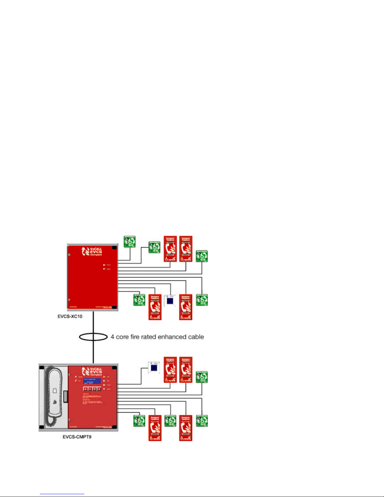
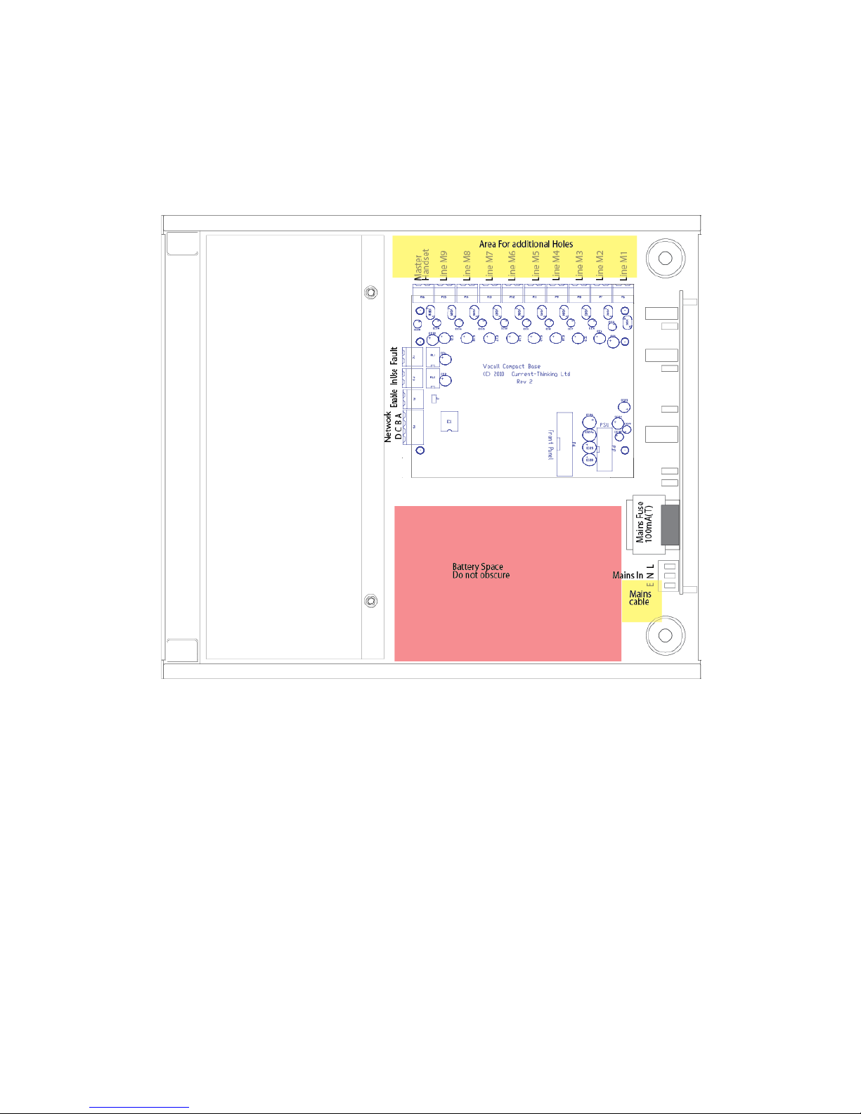
Honeywell EVCS-CMPT9 Guide

EVCS-CMPT9 Compact Master
&
EVCS-XC10 Slave Exchange
Installation, Commissioning and Maintenance Manual
www.acornfiresecurity.com

1
Introduction
An EVCS is a fixed, secure, bi-directional, full duplex voice communication system to assist fire fighters in an emergency in high
rise buildings or large sites where radio communication may not work, and covers the operation of fire telephones, disabled refuge
systems and the Disabled Toilet Alarm.
The Emergency Voice Communications System (EVCS) is designed to fully comply with BS5839-Part 9:2011
(abb. Pt9) for use as a fire telephone system, disabled refuge call system or as a combined system when both fire telephones and
disabled refuge points are required.
Suitability
Fire telephone systems are recommended for all public buildings and multi story buildings over four floors by BS9999.
Disabled refuge systems are required by Building Regulations Approved Document B for all non-domestic dwellings. Building
Regulations Approved Document B also requires all buildings where the public or disabled staff gain access to any floor other than
the ground floor using lifts or stairs are required to exit.
Product Overview
A Compact 9 unit comprises of two functional blocks; the master handset and outstations (type A, type B, duo, jack
points or disabled toilet alarm), with the quantities of these basic units being adjusted to suit the application, a maximum of 19
outstations can be used for this system. Other sized EVCS systems are available.
The Compact unit (EVCS) has been designed on a star topology. In most cases this will reduce the cable requirements
compared to all ring based systems. The topology consists of spurs, with each spur consisting of 1 off 2 core 1mm CSA cables
(see Cable Guidance for Network and Outstations section for cable type). Each spur can be up to 500m.
www.acornfiresecurity.com

2
Important Safety Information
This equipment must only be installed and maintained by suitably skilled and competent person.
This equipment is defined as Class 1 in EN60065 (Low Voltage Directive) and must be earthed.
Caution
INDOOR USE ONLY
WARNING SHOCK HAZARD-
ISOLATE BEFORE OPENING
WARNING
TO REDUCE THE RISK OF FIRE OR
ELECTRIC SHOCK, DO NOT EXPOSE THIS
UNIT TO RAIN OR MOISTURE
W
ARNING
THIS UNIT MUST BE EARTHED
W
ARNING
NO USER SERVICABLE PARTS
Each Compact unit requires a 3A spur, returning to a breaker clearly marked EVCS DO NOT TURN OFF. If the units are
distributed around a site it is essential all units are on the same mains phase as they are classified TEN 230V, powering from
different phases can mean a 440V potential can be present in a unit during a major fault incident.
Anti-static handling guidelines
Make sure that electro-static handling precautions are taken immediately before handling PCBs and other static sensitive
components.
Before handling any static-sensitive items, operators should get rid of any electrostatic charge by touching a sound safety earth,
such as a radiator. Always handle PCBs by their sides and avoid touching any components. PCBs should be stored in a clean, dry
place that is free from vibration, dust and excessive heat.
Storing the PCBs in a suitable cardboard box will also guard them against mechanical damage.
www.acornfiresecurity.com

3
Unpacking the EVCS-CMPT9 Compact Master Unit
Remove the Compact unit from its packing, and check the contents against the following list:
1. EVCS-CMPT9 Compact Master unit.
2. Installation & maintenance manual (this document).
3. User guide & logbook.
4. Accessory pack with the following contents:-
a. Spare mains fuse.
b. 2.5mm AF ALN key.
Using the ALN key supplied, open the right hand front cover.
Verify the following items are present:
1. 9 off outstation line connectors
2. 1 off 2 way fault connector
3. 1 off 2 way in use connector
4. 1 off 2 way access connector
5. 1 off 4 way network connector
If there are any Items missing please contact Honeywell, quoting the unit serial number, and the
name on the packing list enclosed so we can rectify the situation.
www.acornfiresecurity.com

4
Unpacking the EVCS-XC10 Compact Slave Exchange
Remove the Compact unit from its packing, and check the contents against the following list:
1. EVCS-XC10 Compact slave unit.
2. Installation & maintenance manual (this document).
3. User guide & logbook.
4. Accessory pack with the following contents:-
a. Spare mains fuse.
b. 2.5mm AF ALN key.
Using the ALN key supplied, open the front cover.
Verify the following items are present:
1. 10 off outstation line connectors
2. 1 off 4 way network connector
If there are any items missing please contact Honeywell, quoting the unit serial number, and the
name on the packing list enclosed so we can rectify the situation.
www.acornfiresecurity.com

5
Preparation
Remove the front door plate containing the circuit board by unscrewing the door hinge. This has a connection to the base PCB,
which needs to be removed. Exercise static precautions to prevent damage to the electronics. Store the front panel assembly
safely until the master handset is mounted and cables have been attached.
Before mounting the unit on the wall it is advisable to remove the cable knockouts. Decide how the wiring will be brought into the
panel and remove the required knockouts for cable entry. If a knockout is removed, fill the hole with a good quality cable gland.
On the bottom face a single knockout is for the incoming mains. Mains SHOULD NOT enter the box by any other hole. If additional
holes are required, then the can be drilled as shown below, taking care not to obscure the battery or PCB locations.
Unused knockouts must be left unopened to comply with the LVD. Accidentally knocked out holes should be blanked off. This work
must be carried out prior to the re-installation of circuit boards.
www.acornfiresecurity.com

6
Mounting the Compact unit
The Compact unit weighs 4Kgs with batteries, so care should be taken to securely mount the unit on stud walling.
Connecting the Compact unit
To comply with EMC (Electro Magnetic Compatibility) regulations and to reduce the risk of electrical interference in the system
wiring, we recommend the use of fire-resistant screened cables throughout the installation.
All wiring should come into the enclosure via the knockouts provided, and be fixed tidily to the relevant terminals.
Note that correct cable glanding is essential and due regard should be paid to any system specifications which demand a certain
cable type (providing it meets the appropriate national wiring regulations).
Planning the Wiring
All system wiring should be installed to meet the appropriate parts of BS5839-9 (2011) and BS 7671 (Wiring Regulations). Other
national standards of installation should be adhered to where applicable.
Do not test wiring with an insulation tester (Megger) with any equipment or outstations connected, as the 500 Volt test voltage will
destroy these devices totally.
You must observe local wiring regulations. Do not run SELV and LV cables in the same enclosure without adequate insulation
between them.
Mains Connection
Each compact requires a 3A spur, returning to a breaker clearly marked “EVCS DO NOT TURN OFF”. If the units are distributed
around a site it is essential all units are on the same mains phase, as they are classified TEN 230V, powering from different phases
can mean a 440V potential can be present in a unit during a major fault incident.
>3mm
3A
Main
Distribution
Board
>0.75mm
2
<2.5mm
2
UNITY
DA
Compact
9
www.acornfiresecurity.com

7
Batteries
The compact requires one number 12V 5AH sealed lead acid batteries to provide backup power in the event of mains failure as
defined in BS5839pt9 for 24 hours standby and 3 hours operation when powered by normal mains supply.
For 72hour standby and 1 hour operation one number 12V 17AH battery is required, these will need to be fitted in an external
battery enclosure. The monitored charger in the Compact unit is capable of charging and monitoring these batteries.
Safety Information:
Sealed Lead acid batteries contain sulphuric acid which can cause burns if exposed to the skin. The low
internal resistance of these batteries means large currents will flow if they are accidentally short
circuited, causing burns and a risk of fire- exercise caution when handling batteries.
Power up Procedure:
Always apply mains power before connecting batteries. Do not commission the Compact unit
on batteries, as the high inrush current required by the power supply may rupture the battery fuse.
Always connect the Positive (Red +) terminal first, then the Negative (Black -)
To down power reverse the power up sequence.
www.acornfiresecurity.com

8
Outstation Wiring
The compact unit requires programming to determine the outstation configuration;
Four types of handset are allowed on the system, type A (fixed phone) type B (hands-free refuge points), disabled toilet alarms and
jack plates.
For jack points a 10K EOL resistor is required at the OUT of the last plate on the line.
Cable Guidance for Compact Unit and Outstations
Following the publication of BS5839pt9:2011, the guidance on cables for the Compact unit has changed, following a
relaxation in the requirements of the standard.
Type A Outstations
Any system with fire fighting telephones (Type A outstations) must have all wiring to these outstations and any necessary network
cables interconnecting parts of the system in Enhanced fire rated cables.
Type B Outstations
In buildings under 30 metres in height, or any building with sprinklers fitted, the wiring of Type B (hands-free) disabled refuge points
may be in standard fire rated cable as long as the planned evacuation will be completed within 30 minutes. If the building is over
30metres in height without sprinklers, or where the evacuation will take place over multiple stages exceeding 30 minutes, enhanced
fire rated cables must be used.
Disabled toilet call points
The revised BS5839pt9:2011 now recognises the addition of disabled toilet call systems to the Compact unit, however
gives no guidance on their use, as this is in Building Regulations Approved Document M.
There is no requirement for these systems to be monitored or battery backed. However with the EVCS-TA toilet extension we
have included these features as standard. The only cable requirement may come from the building design statement, and typically
this will require low smoke and fume cables (LSF), although they can also be wired in standard fire rated cable for ease of
identification.
Combined Systems
When a system consists of a mix of Type A and Type B outstations, the wiring must be enhanced fire rated for any shared resource
such as network cables, but individual spurs to type B outstations can be wired in standard fire rated cable as long as the distance
covered by that cable does not exceed 30 metres vertically in non-sprinklered buildings, or the evacuation plan for this segment of
the building will not exceed 30 minutes.
General Guidance
In complex buildings or where systems are being quoted without access to the fire evacuation plan we recommend all wiring to be
enhanced, or suitable caveats and detailed assumptions are placed on the design certificate required by BS5839pt9:2011.
www.acornfiresecurity.com

9
Handsets (Type A):
Hands Free Refuge Point (Type B)
Disabled Toilet Alarm
Master to Slave Connection
www.acornfiresecurity.com

10
Auxiliary Connections
The Compact unit has three auxiliary connections as shown below:
In Use Is a normally open volt free relay (30V DC 1A) connection which closes when any outstation is operated.
Fault Is a normally closed volt free relay (30V DC 1A) which OPENS on any fault, including loss of power.
Enable Is a normally CLOSED input and is required to operate the system (if Jumper J1 is in place then no connection is required
at the terminals.
2ND Fix
Replace the front panel door plate by attaching the ribbon cable lead and fixing with the door hinges.
Attach all plugs ensuring they fit squarely into the connectors.
Do not connect battery until the master has been powered up on mains.
Powering UP
Carefully check the outstation wiring then apply AC power to each Compact master unit - DO NOT commission on
batteries as the power supply has a large reservoir capacitor which may rupture the battery fuse if the AC is not present when
powering up the system. Once the system is powered, the battery leads can be attached to the battery.
www.acornfiresecurity.com

11
EVCS-CMPT9 Programming
Status Screen Menu
Honeywell
Compact M9
-Healthy-Calls 0
10:24:01 07|01|11
On power up, or by pressing the * key, the Status Screen Menu can be accessed.
The top line can be changed from the Set Site Name Menu. The second line can be changed from Set Panel Name Menu. The
third line contains the status of the unit. The fourth line shows the current time and date.
The padlock in the top right of the display shows the state of the write protect jumper on the rear of the display PCB. This should be
UNLOCKED to commission the system, and then LOCKED to prevent any unauthorised changes to the commissioned system.
Menu Structure
There are 3 levels of accessibility: User, Manager, and Engineer.
• User level is accessible to all.
• Manager level is accessible to those who log in as Manager or Engineer.
• Engineer level is accessible to those who log in as Engineer.
To access the menus from the Status Screen Menu, press the TICK button.
Note: If panel is installed in a public area, then all operations will be restricted to Manager or Engineer only, except for user menus
only. This includes receiving and initiating calls.
User Menu
>Log in
Accept faults
*
View current faults
*
View fault log
*
View event log
*
View call log
*
View panel version
Back
Items marked * can be configured to display or not at user level (see later).
Manager Menu
>Log out
Accept faults
View current faults
View fault log
View event log
View call log
View panel version
Set time+date
Change manager PIN
www.acornfiresecurity.com

12
Engineer Menu
>Log out
Accept faults
View current faults
View fault log
View event log
View call log
View panel version
Set time+date
Change manager PIN
Change engineer PIN
Log settings
Panel settings
Set site name
Set panel name
Relay settings
Set service date
Panel test
Outstn settings
Network
Navigating Menus
Honeywell
Compact M9
-Healthy-Calls 0
10:24:01 07|01|11
The EVCS-CMPT9 and EVCS-XC10 can be configured from the front panel menu unit or via the compact configuration software
suite, however the network settings need to be configured before programming can commence. To log in to the EVCS-CMPT9,
press the TICK button to show the log in screen:
Compact M9
Back
>Login
View current fault
The log in screen will prompt the user to enter a PIN. The default Engineer PIN is 0000. Use the navigation keys to choose the
correct number, and then press TICK to move to the next number. Repeat until the PIN is entered.
Enter PIN to LOG IN
-0***-
A list of possible menu options is presented. Log out will be currently selected. Use the navigation keys to select the option
required, and press the TICK button.
Compact M9
Network
>Log out
Accept Faults
Log out
This option exits the configuration menu and returns the master unit back to standard operation.
Scroll through the root menu using the navigation keys until Log out is selected. Press TICK to exit.
www.acornfiresecurity.com

13
Accept Fault
This menu is only displayed when a new fault has occurred; entering this menu silences the fault buzzer and places an event in the
event log, then returns the user to the main menu. The accept faults menu will now be hidden until a new fault occurs.
View Current Fault
This menu is an information only menu. It displays only current faults that are present on the system (if any)
Current faults: 1
Missing outstation 4
Scroll through the root menu using the navigation keys until View current fault is selected. Press TICK to enter the View current
fault menu.
Use the navigation keys to scroll through the faults if there are more than three.
View Fault Log
This menu is an information only menu. It displays the last 99 faults that have occurred, recording the type of fault and the date
and time the fault occurred.
Fault 1 of 3
Fault occurred
Missing outstation 4
10:56:02 01|01|11
Scroll through the root menu using the navigation keys until View fault log is selected. Press TICK to enter the View fault log menu.
Use the navigation keys to scroll through the faults, pressing * exits.
View Event Log
This menu is an information only menu. It displays the last 99 events that have occurred, recording the type of event and the date
and time the event occurred. The following are classed as events: Fault acknowledgement, configuration change, log in, log out,
and system initialised (on power up).
Event 1 of 99
Logged On
10:56:02 01|01|11
Scroll through the root menu using the navigation keys until View event log is selected. Press TICK to enter the View event log
menu.
Use the navigation keys to scroll through the events.
View Call log
This menu is an information only menu. It displays the last 999 Calls that have occurred, on this EVCS-CMPT9.
Call 1 of 999
Master handset
Outstation off hook
10:56:02 01|01|11
Use the navigation keys to scroll through the calls.
www.acornfiresecurity.com

14
View Panel Version
The View panel version option will show the EVCS-CMPT9 current software revision and the software version of any EVCS-XC10
slave attached.
Panel Version:Master
Version:1.0
Build:1122
Build Date 02:03:11
Pressing up and down will switch from master to slave, pressing TICK will exit.
Set time+date
Scroll through the root menu using the navigation keys until Set time+date is selected. Press TICK to show the Set time+date
menu.
Set time+date
Date >01|01|11
Time 14:15:06
:Next
This menu shows the current date and time in the following format:
Day|Month|Year
Hour:Minute:Second
The cursor will be on the first option: Day. Use the navigation keys to select the correct day then press TICK to move to the Month
option. Repeat until the current date and time are set and the next option is selected.
Most configuration menus will have the same options located in the bottom right of the LCD screen: Next, Save, and Quit. Pressing
the TICK button selects the option chosen:
Next: Moves cursor back to first option on screen.
Save: Stores information and moves back to the previous menu screen.
Quit: Discards all information on screen, and moves back to the previous menu screen.
Use the navigation keys to select Next, Save, or Quit as desired, then press TICK. Both Save and Quit will go back to the
root menu.
www.acornfiresecurity.com

15
Change Manager PIN
The default PIN to access the configuration menus is 3333, but this can be changed.
Scroll through the root menu using the navigation keys until Change manager Pin is selected. Press TICK to show the Change
manager PIN menu.
There are 2 lines: New PIN and Repeat PIN. The cursor will be on the first digit of the New PIN. Use the navigation keys to
change the digit, and press TICK to move to the next digit. Repeat until all digits have been entered for both the New PIN and the
Repeat PIN, and the Next option is selected.
Change PIN
New PIN 0***
Repeat PIN ****
:Next
New PIN: PIN number that will be used to access the configuration menus.
Repeat PIN: New PIN repeated. If this differs from the new PIN, then the new PIN number will not be ticked, and a warning
message will be displayed on screen.
Use the navigation keys to select Next, Save, or Quit as desired, then press TICK. Both Save and Quit will go back to the root
menu.
Change Engineer PIN
The default Engineer PIN to access the configuration menus is 0000, but this can be changed.
Scroll through the root menu using the navigation keys until Change engineer PIN is selected. Press TICK to show the Change
engineer PIN menu.
There are 2 lines: New PIN and Repeat PIN. The cursor will be on the first digit of the New PIN. Use the navigation keys to
change the digit, and press TICK to move to the next digit. Repeat until all digits have been entered for both the New PIN and the
Repeat PIN, and the Next option is selected.
Change PIN
New PIN 0***
Repeat PIN ****
:Next
New PIN: PIN number that will be used to access the configuration menus.
Repeat PIN: New PIN repeated. If this differs from the new PIN, then the new PIN number will not be ticked, and a warning
message will be displayed on screen.
Use the navigation keys to select Next, Save, or Quit as desired, then press TICK. Both Save and Quit will go back to the root
menu.
www.acornfiresecurity.com

16
Log Settings
The EVCS-CMPT9 has three independent Logs: Faults, Events and Calls. For each of these logs there is a menu to allow you to
set the visibility to non-logged in users, or to clear the log (engineer only).
Scroll through the root menu using the navigation keys until Log settings is selected. Press TICK to show the Log Settings Menu.
Log settings
Back
>Fault log settings
Event log settings
Call log settings
For each log, the following options are available.
Fault Log settings
Show Log >No
Clear log: No
:Next
The cursor will be on the first option, Show log. Use navigation keys to select either yes or no then press TICK to move to the
Clear log option. Pressing TICK again moves cursor to Next option.
Unlike other menus, the next option toggles between Next, Exec, and Quit. Use the navigation keys to select the desired option,
and then press TICK.
Next: Moves cursor back to show log option.
Exec: Executes command to clear log if clear log option is set to yes, and moves back to root menu.
Quit: Moves back to root menu.
Panel Settings
Depending upon location of install, the buzzer can operate in different modes, and the access level used to operate the panel can
be set.
Panel settings >Next
Buzzer mode>Faulty
User flt accept:No
User access:No
The buzzer can operate in 3 modes:
Mute (buzzer does not sound, which is non-compliant to British Standards)
Faulty (buzzer only sounds when the panel is in fault)
Latched (buzzer sounds until the faults are accepted)
User flt access determines if the faults can be accepted at user level. If Yes, then anyone can accept faults. If No, then only a
manager or engineer who is logged into the panel can accept the faults.
User access determines who can operate the panel; this includes initiating and receiving calls. If the panel is located in a public
area, to comply with British Standards, this must be set to No.
www.acornfiresecurity.com

17
Set Site Name
If the site name is to be changed, scroll through the menu options until Set site name is selected, then press the TICK button.
Set site name
>Honeywell <
:Next
The current site name will be displayed on screen, with the cursor on the first character. Use the navigation keys to scroll to the
correct character then press TICK. Repeat until the new site name has been entered.
Pressing TICK on the last character will move the cursor to the Next option. Use the navigation keys to select Next, Save or Quit
as desired, then press TICK. Both Save and Quit will go back to the root menu.
Set Panel Name
On the system each master can be given a unique name, if the master name is to be changed, scroll through the menu options until
Set panel name is selected, then press the TICK button.
Set panel name
>Compact M9 <
:Next
The current master name will be displayed on screen, with the cursor on the first character. Use the navigation keys to scroll to the
correct character then press TICK. Repeat until the new site name has been entered.
Pressing TICK on the last character will move the cursor to the next option. Use the navigation keys to select Next, Save or Quit as
desired, then press TICK. Both Save and Quit will go back to the root menu.
Relay Settings
The In use relay has multiple settings: None, In use, Connected, or Ignored.
None: the relay is ignored.
In Use: the relay closes when any outstation is activated. This is the default setting.
Connected: the relay closes when the master handset establishes a conversation with an outstation.
Ignored: the relay closes if the master handset is not picked up within the defined time.
Relay Settings
Relay> Ignored
Set Time: 0m 10s
:Next
Set service date
The service date is used as a reminder when the next service is due. When this date is reached, it will trigger a service fault which
will remain until the service date is updated.
Scroll through the root menu using the navigation keys until Set service date is selected. Press TICK to show the Set service date
menu.
Set service date
Date >01|06|99
:Next
This menu shows the currently selected service date in the following format:
Day|Month|Year
The cursor will be on the first option: Day.
Use the navigation keys to select the correct day then press TICK to move to the Month option.
Repeat until the desired next service date is set and the next option is selected.
Use the navigation keys to select next, save, or quit as desired, then press TICK.
Both Save and Quit will go back to the root menu.
www.acornfiresecurity.com

18
Panel Test
This menu option performs various tests on the panel in line with BS5839 pt 9 2011.
There are four sub menus.
Panel test
Back
>Battery test
Define outstation
Outstation ring
Test indicators
Battery Test
This menu option performs a battery test when requested. The menu shows the current state of the PSU and the battery. Both the
battery present test and the battery high impedance test are performed automatically (every 15 seconds, and every 3 hours
respectively). However, this menu allows both battery tests to be performed on demand. Typically this is performed when the
batteries have just been added or changed.
Battery test
Mains: OK
Batt : OK
Action>Quit
Press up or down to toggle between Quit and Retest. Press TICK to select that action.
Define Outstation
This menu option will set all outstations to present. This does not permanently save all outstations as present. This is used for
testing purposes only.
Define all handsets
Master>No
Slave:No
:Next
Outstation Ring
This menu option will cause all outstations to ring, for single engineer testing of a system. When an outstation is picked up it is
recorded in the call log.
Define all handsets
Master>Start
Slave:No
:Next
Test indicators
This menu will sound the buzzer, and will flash all panel LEDs, except for the green power LED.
Test indicators
>Quit
www.acornfiresecurity.com

19
Outstation Settings
Scroll to the Outstn settings menu and press TICK. This menu consists of a list of all 20 possible lines (M1 through M9 on the
EVCS-CMPT9 master unit, and S1 through S10 on the EVCS-XC10 slave unit, plus a back option. The outstation location is
shown with the outstation line number, along with a symbol:
Select outstation
S10-outstation 10
> Back
M9-Outstation 1
Unlocked: this outstation exists.
Line through circle: this outstation does not exist or is in fault.
Select the outstation to be configured and press TICK.
This shows a sub menu for each outstation
M9-outstation 1
Back
>Settings
Name
Settings
M9-outstation 1
O’stn not detected
Kind>None
:Next
The second line of the display indicates the status of the extension (present or not detected).
Kind allows you to set the outstation type:
None (no outstation),
Phone (Type A handset),
Refuge (Type B handsfree handset),
Pullcord (disabled toilet alarm).
If an outstation is defined as a Pullcord, the master will emit a continuous tone if the toilet alarm is activated. This tone will cease
when the master handset goes off hook. No call can be established with the toilet alarm.
Set Name
M9-outstation 1
Name
>Extension 1 <
:Next
Use the navigation keys to change the first character of the extension name, and press TICK to move to the next character.
Repeat for all characters. Press TICK on the last character to move the cursor onto Next.
Use navigation keys to select Next, Save, or Quit, and press TICK to select option.
Note: if the memory is protected (locked padlock symbol shown for the exchange), then you will only be able to view this
information.
The cursor will be on the Quit option. Only Next and Quit can be selected. Pressing Quit will move back to the select outstation
menu.
www.acornfiresecurity.com
This manual suits for next models
1
Table of contents
Other Honeywell Emergency Phone manuals