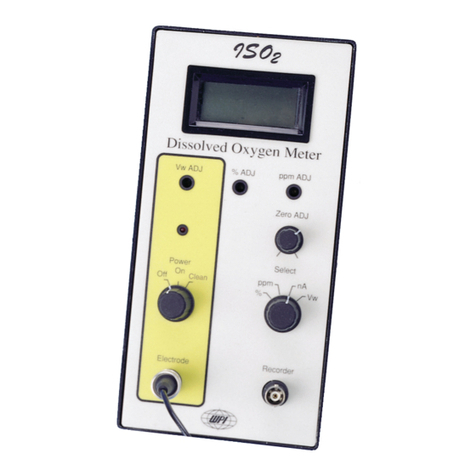
Bellingham and Stanley ADP440 User manual

POLARIMETE
R
A
DP440


ADP440 User Guide (Eng)
Code 37-251
Issue 02
Revision 0
Date September 2006
Bellingham and Stanley Ltd. has been manufacturing high quality optical instruments in the
UK since 1914 and is a leading manufacturer of refractometers and polarimeters. The current
range of products includes optical and digital hand refractometers as well as a full range of
laboratory refractometers and polarimeters available through a network of trained distributors
throughout the world. Process refractometers are also available through specialist outlets.
Our main website gives full details about Bellingham and Stanley Ltd. and our products.
Foreign language brochures in PDF format may be downloaded from this section of the site
by clicking the flag. We apologise if the foreign language brochure of your choice is not
available.
Contact Sales at Bellingham and Stanley Ltd. to discuss a particular application or to receive
details of your local distributor.
Bellingham + Stanley Ltd. recognise all trademarks
©Copyright Bellingham + Stanley Ltd. 2006
Every effort has been made to ensure the accuracy of the contents of the manual. However,
Bellingham + Stanley Ltd. can assume no responsibility for errors contained in the manual or their
consequences.
Printed in UK
Bellingham + Stanley Ltd. Bellingham + Stanley Inc.
Longfield Road, 1000 Hurricane Shoals Road,
Tunbridge Wells, Kent TN2 3EY Building D, Suite 300,
United Kingdom Lawrenceville, USA GA30043
Tel: +44 (0) 1892 500400 Tel: 770 822 6898
Fax: +44 (0) 1892 543115 Fax: 770 822 9165


DECLARATION OF CONFORMITY
According to ISO/IEC Guide 22 and EN 45014
Manufacturer's Name Bellingham & Stanley Limited
Manufacturer's Address Longfield Road,
Tunbridge Wells,
Kent TN2 3EY
United Kingdom
declares that the product
Product Name ADP440 Polarimeter
Model Number All
Is designed to conform to the following Product Specifications:
Safety BSEN60950:1992 + A1 + A2 + A3 + A4 + A11
EMC Emissions
• EN55022: (1998) Radiated Emissions Class A
• EN55022: (1998) Conducted Emissions Class A
Immunity
• EN61000-3-2 Harmonics
• EN61000-3-3 Flicker
• EN61000-4-2 ESD 8kV contact
• EN61000-4-3 EMS 3V/m
• EN61000-4-5 Surges 0.5kV (line to line)
1.0kV (line to earth)
• EN61000-4-11 Power outages 1 cycle/100%
Supplementary The product herewith is designed to comply with the requirements
of the EMC Directive 89/336/EEC and the Low Voltage Directive
73/23/EEC.


Contents 37-256’01 R0 September 2006
contents
Installing the instrument .............................................. 1
Instrument description................................................. 2
Instrument overview ............................................. 2-1
Basic operation..................................................... 2-4
The instrument logs.............................................. 2-14
Sampling techniques............................................ 2-15
Flow-through and water-jacketed tubes............... 2-17
Setting up the system.................................................. 3
Menu flow chart .................................................... 3-1
Shortcut keys........................................................ 3-3
Calibration ............................................................ 3-5
Measurement settings.......................................... 3-8
Methods................................................................ 3-9
User accessibility.................................................. 3-13
21 CFR Part 11 .................................................... 3-17
System settings .................................................... 3-18
Customising the instrument.................................. 3-21
Measurement traceability ..................................... 3-23
Adding extra scales .............................................. 3-25
Special library scales............................................ 3-27
Setting the default values..................................... 3-38
Specification ................................................................ 4
Spares and accessories.............................................. 5


Installing the instrument 37-256’01 R0 September 2006 Section 1
section1
Installing the instrument
Unpacking the instrument .................................... 1-1
Contents list.......................................................... 1-1
Part numbers........................................................ 1-1
Positioning the system ......................................... 1-2
Mains connection ................................................. 1-2
Power requirements ............................................. 1-2
Power supply adapter........................................... 1-2


Installing the instrument 37-256’01 R0 September 2006 Page 1-1
Unpacking the instrument
Carefully remove all of the packing material. It is recommended that the box
and other packing materials are retained so that, should the need arise, the
polarimeter can be safely returned to the manufacturer.
Check that all parts listed below are present and that no transit damage has
occurred. If any are damaged or missing, contact the supplier immediately.
Contents list
1 ADP440 Polarimeter module, see table below for part number
1 Power supply, 55-105
1 Mains lead, see below for part number
1 Polarimeter tube, 35-47
1 Operating Instructions, 37-256
1 Instruction manual CD-ROM, 55-300
Part numbers
ADP440 polarimeter part numbers
Model Complete polarimeter
including power supply Polarimeter module only
ADP440 37-40 37-440
Mains lead part numbers (for use with Power supply 55-105)
Mains cord wire colours
Moulded plug type for Voltage
Line
(Phase)
Neutral
(Return)
Earth
(Ground)
Code
no.
Switzerland 230V - - - 61-181
Denmark 230V - - - 61-182
India / South Africa 230V - - - 61-188
Australia 230V - - - 61-189
No plug – open lead - Brown Blue Green /
Yellow 61-190
UK 13 Amp square pin
to BS1363/A 230V - - - 61-191
United States (3 pin) 110V - - - 61-192
Europe (Schuko) 230V - - - 61-193
I
In
ns
st
ta
al
ll
la
at
ti
io
on
n

Page 1-2 37-256’01 R0 September 2006 Installing the instrument
Positioning the system
Place the instrument on a flat and stable bench that is:
• dry and indoors
• away from draughty or hot equipment like fans or heaters
• out of direct sunlight or strong ambient light
• away from potential sources of interference, such as RFI generating
equipment
• within reach of a power point
• not using a power circuit that also has large motors or noise generating
equipment connected to it
Mains connection
The power supply adapter is supplied with a moulded mains cord and plug,
to suit one of several socket types. For UK lead, replace fuse only with the
type indicated on the plug.
Power requirements
Voltage 110 to 230V ~ ± 10%, 50 to 60 Hz
Maximum load less than 40 mA
Power supply adapter 55-105
RISK OF ELECTRIC SHOCK:
• For electrical safety information, read the label on the power supply.
• For indoor use only.
• Must be kept dry.
• Disconnect the equipment from the mains supply before unplugging the
mains lead from the power supply unit.
• Do not open the power supply adapter. No user serviceable parts
inside.
WARNING:
• Do not cover, designed to operate with free air convection.
• No cleaning required.
Note: A waterproof power supply adaptor, code no. 55-250, which can be
used in damp environments, is available as an optional extra.
I
In
ns
st
ta
al
ll
la
at
ti
io
on
n

Instrument description 37-256’01 R0 Section 2
section2
Instrument description
Instrument overview .................................................... 2-1
The polarimeter .................................................... 2-1
The services panel ............................................... 2-2
The display panel ................................................. 2-3
Basic operation............................................................ 2-4
Switching on ......................................................... 2-4
Switching off ......................................................... 2-4
Switching on for the first time ............................... 2-4
Initial operation after switch on............................. 2-5
Manoeuvring through the menus ......................... 2-6
Keying in letters, numbers and other characters . 2-7
Keying in numerical values ..................................2-8
Display screen information.......................................... 2-9
Taking a reading................................................... 2-10
Blocked light path ................................................. 2-10
Grey result display................................................ 2-10
Zeroing the reading .............................................. 2-11
Optical density...................................................... 2-12
Temperature sensor ............................................. 2-12
Printing the readings ............................................ 2-13
24 column print format ......................................... 2-13
Printer options ...................................................... 2-13
The instrument logs..................................................... 2-14
Setting the default values..................................... 2-14
Measurement settings................................................. 2-15
Mode menu........................................................... 2-15
Measurement settings in detail ............................ 2-16
Remote operation................................................. 2-18
RS232 Serial Port................................................. 2-19
Sampling techniques................................................... 2-20
Cleaning ............................................................... 2-20
Filling the tube ...................................................... 2-20
Cover glass stress................................................ 2-21
Temperature compensation ................................. 2-21
Flow-through and water-jacketed tubes...................... 2-22


Instrument description 37-256’01 R0 Page 2-1
Instrument overview
The polarimeter
The ADP440 polarimeter is a self-contained, easy-to-use instrument suitable
for measuring the rotation of optically active samples. The readings are
displayed in either ºAngular or ºZ (International Sugar Scale) on a backlit
widescreen LCD display. Other reading scales are available see page 3-25.
The instrument is housed in a rigid polyurethane foam moulded case which is
light in weight whilst being extremely rugged and has a high resistance to
chemical attack from the majority of commonly used samples.
Housing:
Low density expanded
polyurethane foam. Lightweight
y
et good mechanical strength
and stability
Display panel:
see page 2-3
Sample chamber:
Open the hinged lids and place
a polarimeter tube or Quartz
Control Plate on the stainless
steel rails
Upper lid:
Can be replaced with optional
slotted lids to suit water-
j
acketed or flow through tubes
Lower lid:
Open to insert a tube

Page 2-2 37-256’01 R0 September 2006 Instrument description
The services panel
CE mark:
Specifies the
instrument conforms to
relevant EU safety and
EMC regulations
Code number:
B+S code number for
the instrument
module.
Serial number:
Always specify this
number in any
communication with
B+S Ltd.
Warning symbol:
See similarly
marked warnings in
this manual
RS232 Serial port 1:
For printing or remote
communication
Power connector:
24V dc from
power supply
Parallel Port
For connecting to a
parallel printer
RS232 Serial port 2:
For connecting either a
barcode scanner or
refractometer

Instrument description 37-256’01 R0 Page 2-3
The display panel
Power indicator
STANDBY — Red
ON - Green
Arrow keys
Forward/Back keys
for negotiating
through menus etc..
Power key:
Press to switch ON
Press for 2 seconds to
switch to STANDBY
Soft key functions
Alpha-numeric keys
‘Telephone style’ keys for
entering letters and
numbers
Soft keys
Functions change
with dis
p
la
y
Operation status bar
Shows the details of the
current o
p
eration
Current time

Page 2-4 37-256’01 R0 September 2006 Instrument description
Basic operation
Switching on
Plug in the power supply and switch on the mains supply. The instrument
will display configuration data and then switch to standby mode with the
power indicator showing red.
To switch on, press the Power Key – the Power Indicator will show green.
Switching off
To switch to standby, press the Power Key and hold down until a
confirmation screen shows (approximately 2 seconds). Press Yes to switch
to standby – the Power Indicator will show red, or press No to continue
operating.
Note: It is preferable for the instrument to be left on continuously even if a
reading is to be taken only once per day.
Switching on for the first time
When the instrument is switched on for the first time after delivery, a ‘Setup
Wizard’ will step you through a number of questions so that the system can
be configured for your particular application.
Initially, select the language required.
Step 1 Select the measurement settings. These are the settings which
measurements are to be taken, the reading scale and temperature
compensation that should be used. When the correct conditions are
selected, press Quit.
Step 2 Set the clock. Adjust the instrument clock to local time.
Step 3 Set the printer options. Select whether readings are to be
printed, stored in memory or both. Set printer configuration.
The Setup Wizard can be run at any time by selecting the Tools menu.
B
Ba
as
si
ic
c
o
op
pe
er
ra
at
ti
io
on
n

Instrument description 37-256’01 R0 Page 2-5
Initial operation after switching on
When the instrument is switched on, the reading mechanism will start-up.
The screen shown below will be displayed briefly.
After a few seconds the following will be displayed. It is important that the
chamber is empty whilst the instrument stabilises.
The instrument will now wait for reading mechanism to reach operating
speed, the vertical progress bar indicates how much longer this will take,
which should take less than one minute. When reached, it will automatically
carry out a zero, this is why the chamber must be empty.
If by accident a tube was in the chamber simply remove it and press ‘Zero’.
The polarimeter is now ready for use.
It is recommended that in order to take accurate readings, allow a further 30
minutes for the instrument to stabilise, as specified in ICUMSA procedures.
B
Ba
as
si
ic
c
o
op
pe
er
ra
at
ti
io
on
n

Page 2-6 37-256’01 R0 September 2006 Instrument description
Manoeuvring through the menus
Menu items can be found and selected by either:
pressing the Up/Down softkeys and then pressing Select
or
pressing the item number key i.e. press 3 for Setup
If the menu item contains a list of options to choose from then either:
select the menu item and then choose the option from the displayed list
or
press the Forward/Back arrow keys to step through the options
Menu items that can be modified by using the arrow keys are identified by
arrows being displayed next to the menu items value (highlighted below).
Return to the Measurement display by repeatedly pressing Quit to step back
through the menus.
B
Ba
as
si
ic
c
o
op
pe
er
ra
at
ti
io
on
n
Table of contents
Other Bellingham and Stanley Measuring Instrument manuals
