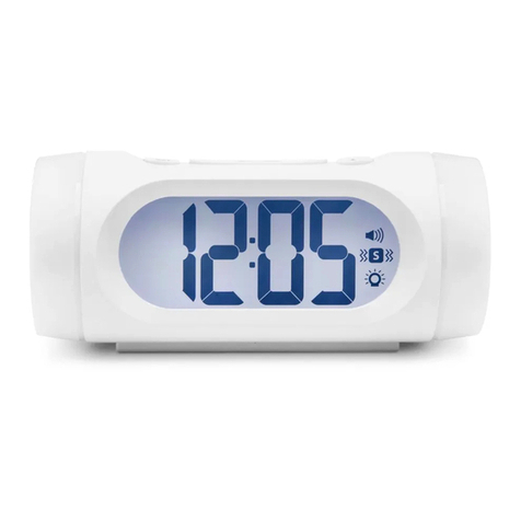
Bellman BE1345 User manual

Bellman Visit System Information
Page 23
Technical Solutions 2005/06
Function
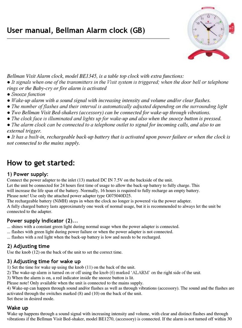
e BE1345 Bellman Visit Alarm Clock is a combined alarm clock
and receiver within the Bellman Visit System for indoor use, which
draws the attention of the user with a flashing light, noise and
one or two BE1270 Bed-shakers (accessory). It is activated by the
clock’s alarm, radio signals from transmitters within the Bellman
Visit System, connection to an external trigger input or via direct
connection to a telephone socket. e snooze function delays the
alarm call for approximately 3.5 minutes and will ignore the external
trigger indicator (17) and telephone indicators from the telephone
connection (19) for up to 45 seconds.
Installation & connection
e unit is usually placed vertically on a level surface
e Bellman Visit Alarm Clock is connected to mains power via the
power supply unit supplied. e Bellman Visit Alarm Clock must
first be connected to mains power for at least 24 hours in order to
operate correctly. For further information see Charging.
e unit is connected to the Bellman Visit System by radio. For
further information see Settings.
It is connected to the telephone via telephone input (19) with the
BE9105 Telephone cord (accessory) and an adapter plug.
An external trigger (17) can be connected to the vibrator output on
several Bellman & Symfon AB products or other equipment that
produces a contact or voltage for activation. For further details see
Technical information.
Testing
e Bellman Visit Alarm Clock must be connected to mains power
using the power supply unit supplied.
Test the flash light, sound and vibration with the BE1270
Bellman Bed-shaker (accessory):
•Turn the dial for Alarm Off/On (9) to position 1.
•Turn the alarm pointer anticlockwise until the clock alarm operates.
• e alarm clock will now flash and vibrate (with accessory BE1270).
A Bellman Visit System transmitter is required to test
the radio reception.
• Press the transmitter test button.
• e Bellman Visit Alarm Clock will respond with a flashing light,
sound signal and vibrations (with accessory BE1270) and the LED
corresponding to the transmitter will light.
Two tests are required to test the external trigger; one to test contact
and another to test voltage. For further information see Technical
Information below. Please note that when the Snooze button is
pressed, the external trigger alarm will be ignored for up to 45 seconds.
• Connect the alarm unit to the external trigger (17) input.
• Activate the alarm.
• e Bellman Visit Alarm Clock will flash, sound and vibrate
(with accessory BE1270).
Bellman Visit Alarm Clock
BE1345
Technical information
Power supply
Mains power: 7.5 V DC / 500 mA with
battery eliminator BE9092 (Europe) and
BE9093 (United Kingdom).
Back-up battery: Internal NiMh battery.
e internal back-up battery must be
changed at a service workshop.
Charging: Via the power supply unit. e
discharged back-up battery will take at least
24 hours to charge.
Radio function
Radio frequency: 433.92 MHz
Number of channels: 64 logical channels
Coverage: e normal coverage between
a transmitter and receiver in the Bellman
Visit System is approximately 80 metres
with a clear line of sight. Coverage is
reduced if walls and large objects screen
off the signal. Any thick walls constructed
of reinforced concrete will greatly affect
coverage.

Bellman Visit System Information
Page 24 Technical Solutions 2005/06
To test the built-in telephone connection:
• Connect input (17) on the Bellman Visit Alarm Clock to an
analogue telephone socket using a BE9105 telephone cable
(accessory) and an adapter plug.
• Ring the telephone number from a mobile phone or
other telephone.
• e Bellman Visit Alarm Clock will flash, sound and vibrate
(with accessory BE1270).
Indicators
Bellman Visit functions
Orange LED (3) indicates a Baby-cry transmitter
Green LED (4) indicates a Door transmitter.
Yellow LED (5) indicates a Telephone transmitter.
Red LED (6) indicates a Smoke alarm transmitter.
When the green (4) and yellow (5) LEDs blink alternately,
the Bellman Visit Alarm Clock is in the channel programming
position and is waiting for a signal from a transmitter within
the Bellman Visit System.
Power supply
When green LED (1) is constantly lit, the unit is being powered
by the power supply unit.
When the green LED (1) blinks in short flashes, the unit is being
powered by the internal back-up battery.
Alarm Clock functions
e snooze button lights when the alarm is activated and blinks
when the snooze function is activated. To conserve the in-built
back-up battery, the snooze button will not light or blink when
the external power supply is disconnected, e.g. during a power failure.
e clock face’s background light will come on when the alarm
clock sounds or the snooze button is pressed.
Signals
e transmitter is the unit within the Bellman Visit System
that determines how the receiver will indicate an alarm. See
transmitter descriptions for further information.
Sound
e Bellman Visit Alarm Clock will sound an alarm call for up
to 30 minutes unless the alarm is turned off or onto snooze. e
sound ranges across several frequencies and increases in volume
to attract attention better. e sound is controlled by a Bellman
Visit transmitter when activated from the Bellman Visit System.
See the section on various Bellman Visit transmitters. e sound
can be turned off/on with switch (11).
Flash
e Bellman Visit Alarm Clock will flash during an alarm call for
up to 30 minutes unless the alarm is turned off or onto snooze.
e flash light can be turned off/on with switch (13).
Vibration
e Bellman Visit Alarm Clock can power up to two BE1270
Bellman Bed-shakers (accessory).
Snooze
e snooze function delays the alarm call for approximately 3.5
minutes and will ignore the external trigger indicator (17) and
telephone indicators from the telephone connection (19) for up
to 45 seconds.
Technical information
Activation via
Alarm call
Inbuilt clock/alarm call function
Radio
Bellman Visit System
Via analogue telephone network:
15 - 90 V RMS, 13 - 60 Hz.
External trigger: 3.5 mm stereo jack plug,
see diagram.
Short circuit between middle pin and outer
pin on the jack plug.
DC: 3 to 28 V between the middle pin (+)
and inner pin (-) on the jack plug.
AC: 3 to 17 V RMS between the middle
pin and inner pin on the jack plug.
Output signals
Built-in sound signal 80 dBA maximum
at 1 metre with a main frequency range
of 500 – 1000 Hz.
Built-in flash light signal:
Approximately 10 candela
Vibrator power: 2.0 – 4.0 V DC
Additional information
For indoor use only
Dimensions WxHxD: 110 x 130 x 92 mm
Weight: 450 g
Colour: White with red base and red
buttons/dials
Flex length: Power supply unit 1.8 m
Accessories
Bellman Bed-shaker BE1270
Bellman External Trigger Cable BE9086
Telephone cable BE9105
Adapter plug for the appropriate country
U
Input voltage circuits
DC
AC RMS
3 to 28 V
3 to 17 V
+-

Bellman Visit System Information
Page 25
Technical Solutions 2005/06
1. Green diode
2. Alarm pointer
3. Orange diode
4. Green diode
5. Yellow diode
Settings
Changing the radio channel
All Bellman Visit System units are supplied from the factory
tuned to the same channel, channel 0. is means that all radio
channel switches on the transmitter are set to the ‘off’ position.
• To change the channel, set a Bellman Visit transmitter to the
desired channel position.
• Hold down the snooze button on the Bellman Visit Alarm
Clock until the green (4) and yellow (5) LEDs blink alternately.
• Press the Bellman Visit Transmitter test button. All the LEDs
on the Bellman Visit Alarm Clock will now blink five times in
quick succession to indicate a successful channel change.
Please note: All Bellman Visit
products within the same system must
be tuned to the same channel in order to
operate as a group. The only exception is the
Bellman Visit Fire Alarm Transmitter, which
does not have adjustable channels. As a
safety precaution, the Visit System receiver
will sound when a fire alarm signal is
detected, regardless of the channel to which
the receiver has been programmed.
Functions
Pushbutton (8)
e snooze function delays the alarm call for 3.5 minutes and will ignore
the external trigger indicator (17) and telephone indicators from the
telephone connection (19) for up to 45 seconds. e snooze button will
also light up the background lighting for 5 seconds.
Switch (9) Alarm (alarm call) Off/On
Switch (11) Sound signal Off/On
Switch (12) Adjusts signal type during external activation. See * below. *
Switch (13) Flash light Off/On
Knob (14) Adjusts alarm call setting. Turn anticlockwise only.
Knob (15) Adjusts time setting.
6. Red diode
7. Light sensor
8. Snooze button
9. Alarm dial
10. Base
11. Sound switch
12. Signal switch for external trigger
13. Light signal switch
14. Alarm call knob
15. Time setting knob
16. Power adapter input
17. External trigger
18. Vibrator output
19. Telephone input
20. Programming switch

Bellman Visit System Information
Page 26 Technical Solutions 2005/06
* Indicators and signals activated by external trigger can be altered using switch (12).
DIP switch settings
Up, Down, Not Used Sound LED Vibration
1 x ding dong, low-frequency tone Green LED Long
1 x ding dong, high-frequency
tone Yellow LED Long
2 x ding dong, low-frequency tone Orange LED Long
2 x ding dong, high-frequency
tone Red LED Long
1 x long ring, low-frequency tone Yellow LED Short
1 x long ring, high-frequency tone Green LED Short
2 x ring ring, low-frequency tone Orange LED Short
2 x ring ring, high-frequency tone Red LED Short
Fire Red LED Constant
VMA Alternating red – orange
LED Constant
Baby-cry transmitter Orange LED Long
Troubleshooting
Problem Solution
e flash light does not work. Check that switch (13) for light is set to the ON position.
Check that the power adapter is connected to both the wall and unit
sockets and that the back-up battery is charged – see “Power supply”.
e sound from the clock does not operate. Check that switch (11) for sound is set to the ON position.
Check that the power adapter is connected to both the wall and unit
sockets and that the back-up battery is charged – see “Power supply”.
e Visit signal indicator does not work. Check that the correct radio channel is selected. For further
information see “Settings”.
Check that the receiver is not placed too far away, by moving the
receiver closer to the transmitter.
e receiver emits a signal even though neither the door
nor telephone is ringing.
Change the radio channel on all Visit System receivers and
transmitters.
U
Input voltage circuits
DC
AC RMS
3 to 28 V
3 to 17 V
+-
Other Bellman Alarm Clock manuals
