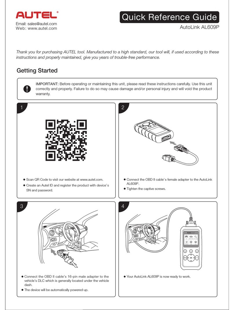
Belltech 5008 User manual

5008-888 8/05 ©
A Division of KW AUTOMOTIVE North America, Inc. 1
INSTALLATION INSTRUCTIONS
--1075 North Ave. Sanger, CA 93657-3539 local: 559-875-0222 fax: 559-876-2259 toll free: 800-445-3767--
5008
AIR JACK KIT
(WITH BELLTECH C-NOTCH)
1999-UP CHEVROLET SILVERALDO
Congratulations! You were selective enough to choose a BELLTECH PRODUCT. We have spent
many hours developing our line of products so that you will receive maximum
performance with minimum difficulty during installation.
Note: Confirm that all of the hardware listed in the parts list is in the kit. Do not begin installation if
any part is missing. Read the instructions thoroughly before beginning this installation.
Warning: DO NOT work under a vehicle supported by only a jack. Place support stands securely under
the vehicle in the manufacturer’s specified locations unless otherwise instructed.
Warning: DO NOT drive vehicle until all work has been completed and checked. Torque all hardware to
values specified.
Reminder: Proper use of safety equipment and eye/face/hand protection is absolutely necessary when
using these tools to perform procedures!
Note: It is very helpful to have an assistant available during installation.
RECOMMENDED TOOLS:
•Properly rated floor jack and 4 (2) support stands
•Wheel chocks
•Drill motor with 5/16” twist drill bit
•Standard socket wrench set
•Standard box wrench set
•½” drive torque wrench (lb-ft)
•Safety glasses
!PLEASE NOTE: For your safety and to prevent possible damage to your vehicle, do not exceed the
maximum load recommended by the vehicle manufacturer (GVWR). Although your Air Assist Springs are rated
at a maximum inflation pressure of 100 P.S.I., this pressure may allow you to carry more than specified GVW on
some vehicles. It is best to have your vehicle weighed once it is completely loaded and compare that weight to the
maximum allowed. Check your vehicle owner's manual or data plate on driver's side door for maximum loads
listed for your vehicle
,SAFETY REMINDER: PROPER USE OF SAFETY EQUIPMENT AND EYE/FACE/HAND PROTECTION
IS ABSOLUTELY NECESSARY WHEN USING THESE TOOLS TO PERFORM
PROCEDURES!
KIT INSTALLATION
As this is a relatively involved installation, we recommend that a qualified mechanic at a properly equipped
facility perform it. We also recommend that the installation be performed on a firm, flat and level surface,
such as seasoned asphalt or concrete. The use of safe and properly maintained equipment is very important!

5008-888 8/05 ©
A Division of KW AUTOMOTIVE North America, Inc. 2
1. JACKING, SUPPORTING AND PREPARING THE VEHICLE
a) Block the front wheels of the vehicle with appropriate wheel chocks.
b) Loosen, but DO NOT REMOVE, the rear wheel lug nuts.
c) Using a properly rated floor jack, lift the rear of the vehicle off the ground. Lift the vehicle so
that the rear tires are approximately 6-8 inches off the ground surface.
d) Support the rear of the vehicle using two (2) support stands, rated for the vehicle’s weight. The
stands should be positioned, in the factory specified locations, one on each of the frame rail.
Prior to lowering the vehicle onto stands, make sure the supports will securely contact the
straight, flat portions of the frame rails.
e) Support the rear axle with support stands, one located on each end. Be careful not to lift
vehicle off of support stands
!It is very important that the vehicle is properly supported during this installation to prevent frame
damage and personal injury! Make sure that the support stands are properly placed prior to
performing the following procedures.
,SAFETY REMINDER:Check for safe vehicle stability before proceeding under the vehicle to begin
the following procedures. Never work under a vehicle supported by only a jack. Always use properly
rated support stands to support the vehicle.
2. FITTING THE UPPER BRACKETS
a) With the rear of the vehicle supported, remove the rear wheals.
b) Working from either side of the vehicle, remove the four bolts from the rear of the Belltech C-
notch (Photo 1).
c) Slide the upper bracket onto the frame rail, making sure that the upper bracket sits flat against
the C-notch (Photo 2).
d) Attach the upper bracket to the C-notch with the necessary hardware provided in the kit (Photo
3).
e) Locate the 5/16” hole on the upper bracket (Photo 4). Use a 5/16” drill bit and drill motor to
make the airline hole in the frame rail (Photo 5). Thoroughly de-burr the holes with a small
round file or de-burring tool.
3. PARKING BRAKE CABLE RELOCATION / DRIVER’S SIDE
a) From the driver’s side, unbolt and remove the stock brake clamp from the cable. The clamp is
located on the shock mount.
b) Attach the new clamp in the same location of the old clamp.
c) Insert the u-bolt clamp around the axle and between the bump stop plate and the spring pad.
While holding the u-bolt and bracket in place, attach the new brake clamp onto the u-bolt end.
d) Thread the bolts on the u-bolt and tighten securely to the axle.

5008-888 8/05 ©
A Division of KW AUTOMOTIVE North America, Inc. 3
3a. PASSENGER SIDE
e) From the passenger’s side, attach the new clamp onto the parking brake cable between the
stock clamp and the cable end (Photo 11).
f) Insert the u-bolt clamp around the axle and between the bump stop plate and the spring pad
(Photo 11). While holding the u-bolt and bracket in place, attach the new brake clamp onto the
u-bolt end (Photo 11-12).
g) Thread the bolts on the u-bolt and tighten securely to the axle.
4. AIR SPRING INSTALLATION
a) Pre-assemble the air helper spring to the lower bracket using one 3/8 -16 x 3/4” HHCS and one
3/8 A325 Flat Washer, attaching the bag to the lower bracket (Photo 6). Make sure that the
holes on top of the air spring are positioned correctly to line up with the holes on the upper
bracket.
b) Remove the U-bolts and the U-bolt plates from the axle (Photo 7).
c) Place the air spring assembly on the top of the leaf spring pack under the axle saddle. The air
spring should be towards the rear of the vehicle in relation to the axle (Photo 8).
d) Re-install the U-bolts and U-bolt plates (Photo 9).
e) Fasten the air spring to the upper bracket using two 3/8 -16 x 1” HHCS and two 3/8 A325 Flat
Washer. Make sure the air inlet is visible through the large access hole in the upper bracket.
(Photo 10)
f) Install the brass elbow fittings into the air spring through the large access hole in the upper
bracket. Tighten the air fitting securely to engage the thread sealant. Position the elbow so it
points in the anticipated location of the air inflation valve (Photo 11).
g) Repeat steps 4a-4f for other side of vehicle.
5. AIR LINE AND INFLATION VALVE INSPECTIONS
a) Uncoil the airline tubing and cut it into two equal lengths.
,Safety Reminder:DO NOT FOLD OR KINK THE TUBING. Try to make the cuts as square as
possible!
b) Insert one end of one of the lengths of tubing into the elbow fitting installed in the top of one air
helper spring. Push the tubing into the fitting as far as possible and run the airline through the
5/16” hole in the upper bracket (Photo 12).
c) Route the airline through the back of the Belltech C-notch (Photo 13) and through the 5/16”
hole on the bracket on the other side of the vehicle. Insert the loose end into the other fitting
so that the airline runs from one air spring to another.
d) Cut the airline that connects the air springs in half, at the center of the vehicle and install the
“T” Fitting that is supplied in the kit.

5008-888 8/05 ©
A Division of KW AUTOMOTIVE North America, Inc. 4
e) Select a location on the vehicle for the air inflation valve. Recommended locations are on the
bumper or the body of the vehicle, but you can mount it anywhere as long as it is in a protected
location where the valve will not be damaged. Be sure to maintain accessibility and clearance
for the air chuck when choosing a location.
f) Drill a 5/16" hole and install the air inflation valve using two 5/16" flat washers and nuts per
valve as supports (Photo 14: Small mounting bracket shown for installation illustration only, not
included in kit). Run the tubing from the “T” fitting to the valve, routing it to avoid direct heat
from the engine and exhaust system. Also, be sure to keep the airline away from sharp edges.
NOTE: The airline tubing should not be bent or curved sharply as it may collapse. Secure the
tubing in place with the nylon ties provided. Push the end of the airline tubing into the inflation
valve.
6. CHECK THE AIR SYSTEM
Once the inflation valve is installed, inflate the air helper springs to 70 P.S.I. and check the
fittings for air leaks with an applied solution of soap and water. If bubbles are detected at a
tubing connection, check to make sure that the tube is cut as square as possible and that it is
pushed completely into the fitting. The tubing can easily be removed from the fittings by
pushing the collar towards the body of the fitting and then pulling out the tube. If a leak is
detected where the brass elbow fitting screws into the spring, remove the tubing, then screw
the elbow into the spring one additional turn or until the leak stops. Re-install the tubing and re-
inflate the air springs and check for leaks as noted above.
7. FINALIZING THE INSTALLATION
a) Re-install wheels and torque lug nuts to the Manufacturer’s specifications.
b) Check that all components and fasteners have been properly installed, tightened and
torqued.
c) Lift vehicle and remove support stands. Carefully lower vehicle to ground.
d) Check brake hoses, cables and other components for any possible interference.
e) Check for air spring to chassis/wheel interference.
f) Immediately test-drive the vehicle in a remote location so that you can become accustomed
to the revised driving characteristics and handling.
g) Check all of the hardware and re-torque at intervals for the first 10, 100, and 1000 miles.
!Before finalizing the installation, check once again to be sure you have proper clearance around the
air springs. With a load on your vehicle and the air helper springs inflated, you must have at least 1/2"
clearance around the air springs. As a general rule, the Air Assist Springs will support approximately 50
Ibs of load for each P.S.I. of inflation pressure (per pair). FOR BEST RIDE use only enough air pressure in
the air helper springs to level the vehicle when viewed from the side (front to rear). This amount will vary
depending on the load, location of load, condition of existing suspension and personal preference.

5008-888 8/05 ©
A Division of KW AUTOMOTIVE North America, Inc. 5
5008
(1999-UP CHEVROLET SILVERALDO AIR JACK KIT)
Part # Description Quantity
5008-010 Upper Bracket (Left Side) 1
5008-030 Upper Bracket (Right Side) 1
5001-005 Lower Bracket 2
5000-200 Air Bag 2
110424 1/2-20 x 3 3/4 HHCS 4
110409 1/2-20 x 1 1/2 HHCS 4
110660 1/2" A325 Flat Washer 16
110403 1/2”-20 Nylock 8
112086 3/8–16 x 1 HHCS 4
110625 3/8 A325 Flat Washer 6
110258 3/8 -16 x 3/4 HHCS 2
5096-015 1/4 Elbow Fitting 2
5096-020 1/4 “T” Fitting 1
5096-017 1/4 Schrader Valve 1
9999-975 Nylon Ties 7” 6
112258 U-Clamp 3” 2
5008-301 ½” Insulated Clamp 2

5008-888 8/05 ©
A Division of KW AUTOMOTIVE North America, Inc. 6

5008-888 8/05 ©
A Division of KW AUTOMOTIVE North America, Inc. 7
Table of contents
Popular Other manuals by other brands

PTP Turbo Blankets
PTP Turbo Blankets Turbo Blanket Installation instructions manual
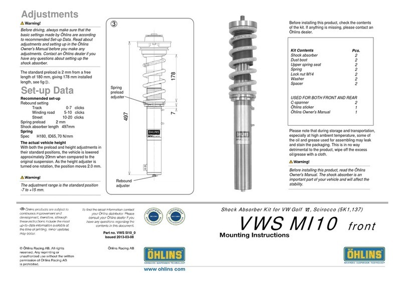
Ohlins
Ohlins VWS MI10 Mounting instruction

NEC
NEC NEC020513 Applications
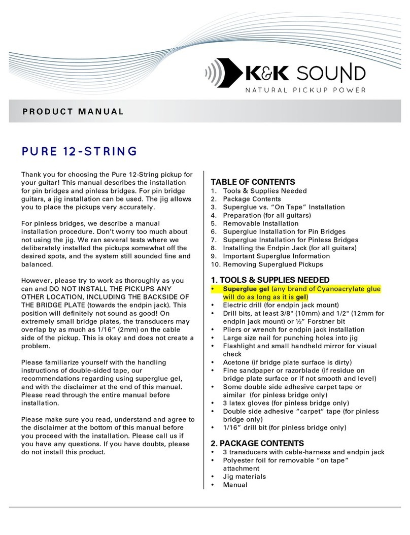
K&K Sound
K&K Sound PURE 12-STRING product manual
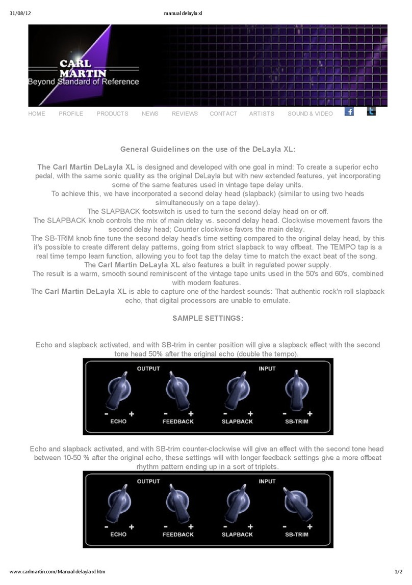
Carl Martin
Carl Martin DeLayla XL Short instruction manual
Trackunit
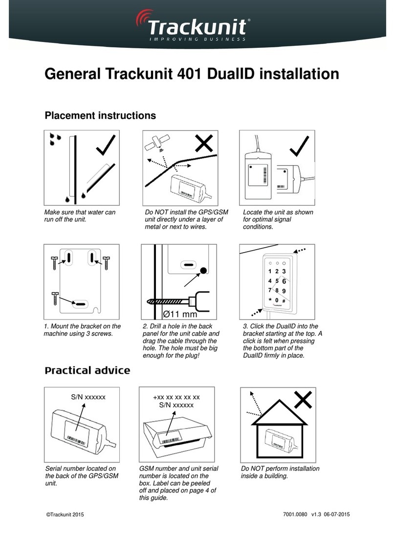
Trackunit 401 DualID Installation

Ramsey Winch
Ramsey Winch Patriot Profile 9500 owner's manual
Mustee
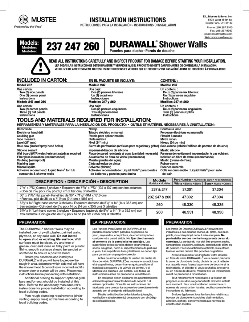
Mustee DURAWALL 237 installation instructions

HTC
HTC Vive Focus Get started

Siemens
Siemens Simatic RF600 System manual
Truma
Truma Multivent TBM Operating instructions & installation instructions

Prime Water
Prime Water Prime LC-11 user manual
