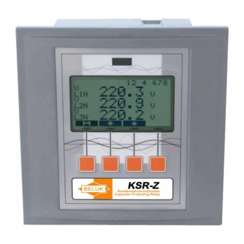
Beluk KSR-V Guide

Technical Documentation
KSR-V –Capacitor-Bank Protection Relay
Rev. 05
2
Revision history
Date
Name
Revision
Change
26.05.04
CE
01
initial document release
02.05.10
Le
02
General update
12.08.10
Le
03
General update
02.11.10
Le
04
Change website
18.07.18
SO
05
Content correction

Technical Documentation
KSR-V –Capacitor-Bank Protection Relay
Rev. 05
3
Content
1OVERVIEW ................................................................................................................................................ 4
2MEASUREMENT SYSTEM ....................................................................................................................... 5
2.1Connection diagram .............................................................................................................................................5
2.2 Data collection.......................................................................................................................................................6
2.3 Measured values....................................................................................................................................................7
3RELAYS..................................................................................................................................................... 7
4ALARM SYSTEM....................................................................................................................................... 8
4.1 Schematic diagram ...............................................................................................................................................9
5USER INTERFACE.................................................................................................................................. 10
5.1 Main menu...........................................................................................................................................................10
5.2 Submenu "measurement"..................................................................................................................................11
5.3 Submenu “auto-roll” ..........................................................................................................................................11
5.4 Submenu "harmonics".......................................................................................................................................12
5.5 Submenu "setup"................................................................................................................................................13
5.6 Submenu "device info" ......................................................................................................................................17
5.7 Submenu "reset min/max”.................................................................................................................................17
5.8 Alarm display......................................................................................................................................................18
6TECHNICAL DATA.................................................................................................................................. 19

Technical Documentation
KSR-V –Capacitor-Bank Protection Relay
Rev. 05
4
Important Information!
If the above sign appears besides a text passage in the manual the reader is strongly
advised to read the corresponding information, as it is very important for the device
usage! It can contain safety advice or other information for the correct handling of the
device.
If the information is disregarded, the device may be inoperable or even damaged!
1 Overview
The KSR-V Capacitor Protection relay has been designed to protect capacitors from damage due to over-
voltage. Especially the capacitors which are used in reactive power compensation systems have to be
supervised and, if the danger of capacitor damage is given, have to be shut down. This is the function a
KSR-V can perform in a very flexibly way.
The device provides a big liquid crystal display for easy reading of values and settings. The backlight
provides a good visibility even in poor light conditions. Four context-sensitive soft-keys provide easy, intuitive
usage without the need to read the manual along when using the device.
A basic set of standard values (voltages) is calculated from measured input data. These are then used to
calculate further values.
Nearly all calculated values are true RMS (TRMS) values, which means they are correct even if the
waveform is not a sine function.
A full range “Fast Fourier Transformation” is performed on the input data of all channels. This provides
information about the harmonic contents which distort the sine waveform of the voltages.
The modular concept of the device enables us to develop a wide range of extension modules without the
need for a re-design of the KSR-V main unit. Please ask for the actual available modules.
!

Technical Documentation
KSR-V –Capacitor-Bank Protection Relay
Rev. 05
5
2 Measurement System
The KSR-V measurement system provides 7 input channels:
For Voltage measurement the connectors L1, L2, L3, (N) have to be connected witch the corresponding
points of the supervised system. The connection of N is not necessary in all cases. If left open, an artificial N
potential is provided by an internal resistor network.
Voltage measurement channels V1-4 via voltage measurement transformers (secondary connections open
delta). A maximum of 4 voltage channels is available.
The KSR-V provides separate input terminals for the device supply voltage. It has to be connected regarding
the specifications written on the type label. The supply voltage can also be connected to the power system to
be measured.
2.1 Connection diagram

Technical Documentation
KSR-V –Capacitor-Bank Protection Relay
Rev. 05
6
2.2 Data collection
The waveforms of the signals (=voltage) on the input channels are sampled by the data collection logic of the
KSR-V. This presents the software with enough information to calculate all the values.
The sampling of the input signal needs to be synchronized to the input signal. The KSR-V
uses voltage L1-N for this purpose. If this voltage is too small or even disconnected, the
device can not do calculations synchronously. In this case, a frequency of 50 Hz/cps is
assumed and the data acquisition works accordingly.
The data collection circuitry for the voltage channels uses seven terminals (L1, L2, L3, N, V1-4), which have
to be connected in accordance to the connection diagram. As a minimum, the L1/L2/L3 terminals have to be
connected while N can be left floating. In this case, N is artificially generated inside the device by three
resistors in a star-connection. Connection of the N-terminal overrides the internal high-impedance resistor
circuit. The voltages can be connected directly (with respect to the maximum rating) or via transformers. In
this case, a factor between 1 and 4000 can be presented to the KSR-V, which resembles the voltage
conversion factor of the measurement transformers. The device will use this factor to provide corrected
readings for all voltages.
Always make sure, you don’t exceed the maximum ratings of the voltage channels. The ratings and a
connection diagram are available on the labels on the back of the device and in the "Technical Data"
chapter. If these ratings are exceeded, severe damage may be done to the KSR-V!
Each input channel contains a high precision input filter with a 3dB-cutoff-frequency in the range of 2.5kHz -
3 kHz. This protects the system from being damaged by transients with high frequencies like voltage spikes
and ensures the synchronisation of the measurement system to the input signal in presence of high
frequency harmonics.
!

Technical Documentation
KSR-V –Capacitor-Bank Protection Relay
Rev. 05
7
2.3 Measured values
The KSR-V measurement system acquires amplitudes and waveforms of the voltages which are connected
to the measurement inputs. The signal processor calculates different values from that information:
ULN: TRMS voltages L1-N, L2-N, L3-N
ULL: TRMS voltages L1-L2, L2-L3, L3-L1
THD UL1-3: THD - factors for voltages L-N
T: ambient temperature
V 1-4: TRMS voltages connected to voltage input channels V1-4
Vf 1-4: voltage of fundamental waves connected to voltage input channels V1-4 (without harmonics!)
Vth 1-4: exponentially damped voltage values to simulate thermal measurement connected to voltage
input channels V1-4
THD V1-4: THD - factors for voltages connected to voltage input channels V1-4
Harmonics: order 2-63 for voltages UL1-3 and V1-4
3 Relays
Depending on the ordered type the KSR-V is equipped with up to 6 output relays of different types (change
over contacts, closing contacts). Also 4 optocoupler outputs are possible.
None of the relays has any special function, they can all be used for alarm purposes (respect technical
data!).
An alarm relay is triggered by a signal which is received from any of the alarms. It can be configured to be
“normally open” or to be “normally closed“. This setting allows the inversion of the relay function.
Further, each relay can be set to “reset automatically” or to “manual reset”.
All these settings are located in menu “setup relay”.
Relays, which are not assembled in a device, are displayed as “not available” in the menus.

Technical Documentation
KSR-V –Capacitor-Bank Protection Relay
Rev. 05
8
4 Alarm system
The user can configure up to 32 alarms. Each single alarm continuously compares one measured value
(=alarm source) to a corresponding limit value. If the trigger condition becomes true, it delivers activation
signals to achieve some reaction (relay activation, display alarm).
Each alarm provides the following features:
selectable alarm source from all measured values (though not single harmonics!). Harmonics
supervision can be achieved by using the THD as alarm source!
selectable limit for each alarm
selectable trigger condition (either “value>limit” or “value<limit”)
alarm-specific turn-on delay time
alarm-specific turn-off delay time
selectable alarm outputs (relays or display message with choice for "trip" or "alarm" )
This alarm system reaches its maximum flexibility by these features:
multi-source alarm
One single output relay can be triggered by any of the 32 alarms. More than one alarm can be used to
trigger the same relay. In this case, only one of the alarms is sufficient to activate the relay (logical OR).
As each alarm first handles the necessary delay times before sending the trigger signal to the relay, different
delay times from the alarms, which are sourcing a relay, are handled correctly!
multi-target alarm
One alarm can trigger a free configurable set of relays after the delay time is finished. This obviously
includes the activation of more than one output relay.
relay inversion
Each output relay can be set to be inverted. This means that the relay is normally closed and will open on
activation. This selection is valid for all alarms, which use the relay as a target.

Technical Documentation
KSR-V –Capacitor-Bank Protection Relay
Rev. 05
9
manual/automatic relay-reset
By setting a relay to “manual reset”, one can inhibit the automatic reset of the relay to the reset state when
the activation by the alarms is reset. This “hold”-condition is stored in the KSR-V non-volatile memory, so it is
correctly available even after supply failure. The user has to reset the relays manually to bring them back to
their reset state.
The manual reset feature should not be used in an environment, where manual resets would be triggered
automatically by an external computer system via bus and if the manual reset would happen too frequently.
The memory chip, which is used to store the ”hold”-state of the relays has specified some 100000 write
cycles. This is enough for manual operation but it can be exceeded with frequent automatic resets.
4.1 Schematic diagram
This diagram shows the set-up for one single alarm. All of the 32 alarms work similar.
on-delay
off-delay
relay 1
relay 2
relay 3
relay 4
relay 5
relay 6
relay 7
relay 8
output
selector
source
selector
value 1
value 2
value x
value N
comparator
value > limit
comparator
value < limit
limit
limit
trigger selection
DISPLAY
ALARMTYPE
Reset: Auto/Man

Technical Documentation
KSR-V –Capacitor-Bank Protection Relay
Rev. 05
10
5 User Interface
The KSR-V uses a graphical LC display with automatic backlight for showing the measurement values and
the device settings.
The device provides 4 keys to the user to accept any inputs. The action, a key performs, depends on the
actual context and is given by small icons in the bottom line of the display. This means a much more easy
and intuitive usage of the device, even in complicated situations and settings.
5.1 Main menu
The main menu is the central point of menu navigation. Here you can directly enter all submenus or the
measurement display.
The main menu shows the following menu items for configuration or measurement display:
measurement = display measured values
auto-roll = display measured values with automatic value rotation
harmonics - This submenu shows the single harmonics for all input channels
setup - The device settings can be found inside this submenu
device info -This submenu shows some information about the device
reset min/max = reset minimum/maximum values
KEYS:
The user can navigate through the menu entries by use of the "" and "" keys. On the left side of the
topmost item, a tiny arrow ( ">" ) shows which item is actually selected. By pressing "", one can enter into
the selected submenu. The left key is not used in the main menu.
After connecting the supply voltage the device automatically starts with the submenu
"measurement"!
Whenever a capital "M" is used as key symbol in any sub-menu, pressing the key will
switch straight to the main menu.
!

Technical Documentation
KSR-V –Capacitor-Bank Protection Relay
Rev. 05
11
5.2 Submenu "measurement"
This menu holds nearly all the measured values. Each value is displayed together with its name (ULN,
ULL,... ) and its origin (L1, L2, L3, …). The units, together with appropriate unit-prefixes, are also available.
Use keys "" and "" to select from the variety of measured values.
The KSR-V stores the maxima and minima for each value. The display can be switched to show them
instead of the actual value. The right key is labelled “min”, “max” or “val”, according to the selected value.
Press it to change between them.
In the top line, the set of relays (if the are assembled in the device) is shown. A dark number on bright
ground represents an inactive relay. Inverse display (bright number on dark ground) indicates an activated
relay.
The "M" - key switches back to the main menu.
5.3 Submenu “auto-roll”
This menu contains nearly the same set of values as the "measurement" menu, but it features an automatic,
timer controlled, switch function to the next value.

Technical Documentation
KSR-V –Capacitor-Bank Protection Relay
Rev. 05
12
5.4 Submenu "harmonics"
The KSR-V calculates harmonics for all input channels. Harmonics are available in the range from the
fundamental wave up to the 62nd harmonic. Both, even and odd harmonics are displayed in this submenu. If
the harmonic display quotes “not available”, the voltage, which sources the harmonic calculation is below a
certain limit or even not present. This makes the FFT calculation of the harmonics very inaccurate or
impossible.
At the top of the display there is the word "harmonics" followed by the data source (e.g. "U-L2"). The
harmonics are displayed in two columns: even harmonics on the left side (2, 4, 6, …), odd harmonics on the
right side (3, 5, 7, …). The numbers before the harmonic value give the order of the harmonic.
The harmonics are normalized to the fundamental wave and displayed in percent of it. The
fundamental wave is always 100.0%, because of this it is not displayed!
KEYS:
left key ("M") switches back to main menu
"" - key scrolls the list of harmonics down to the harmonics of higher order
"" - key scrolls the list back to the top (lower harmonics)
right key ("") switches between the seven data sources (UL1-3 and V1-4)
Single harmonics, as displayed inside this menu, cannot be the source of alarms. Harmonic alarms should
use the THD as source, which contains information of all harmonics of one source in one single value.

Technical Documentation
KSR-V –Capacitor-Bank Protection Relay
Rev. 05
13
5.5 Submenu "setup"
The “setup”-menu contains all settings, which can be performed by the user of the KSR-V to adjust it to
certain ambient circumstances. To enter this submenu, a password is necessary. The fixed password is
"2402". Because there are many possible settings, the "setup"-menu divides up into more submenus to
provide easy and logical access to the setup features:
parameter: This submenu provides the possibility to set certain system parameters, like transformer
ratios and others.
modbus: This submenu contains all settings for the Modbus interface.
relay: This submenu allows to set the relay inversion for alarm relays and the setting "manual reset"/
"automatic reset".
alarm: This submenu contains the settings for the 32 alarms.
Load default: This resets all relay settings, parameters and alarm settings to standard values.
Reset relays.: This resets all relays, which are configured with the “manual reset” setting. By
selection of this menu entry, the relays are set back to inactive state. A new alarm will re-activate the
hold state for the relay.
KEYS:
Select a submenu with the arrow-keys ("" and "") and enter it by pressing the "" - key. You may get to
another submenu or be prompted for confirmation. You can confirm by selecting "yes".
The left key ("M") switches back to the main menu.
5.5.1 Input of numerical values
Inside the "setup"-menu and its submenus, the user will at certain points encounter the problem to enter
numerical values. Whenever the KSR-V prompts for the input of a value, the routine will be the same:
A preset-value will be displayed with the first (highest) digit underlined by a "_". This digit can now be
changed by use of the keys which are labelled with "+" and "-" signs. If no change can be encountered while
pressing these buttons, the value may be at its minimum or maximum, so just try the other key or change to
the next, smaller digit by use of the "" key. After changing, the next digit will be also underlined with a "_"
and can now be altered just like the first one. To store the value, proceed to the least significant digit on the
right side. Press the "" key once more, and the new value will be saved and used.
At any time, one can go back to the menu he came from without changing the value by pressing the “” key.
In this case the modified value will not be used!

Technical Documentation
KSR-V –Capacitor-Bank Protection Relay
Rev. 05
14
5.5.2 Submenu "setupparameter"
Select one of the submenu entries with the arrow-keys ("" and "") and activate it by pressing the "" key.
The "" key will switch back to the "setup" menu.
The "parameter" submenu allows the changing of the following parameters:
vt ratio: This sets the device to work with a voltage measurement transformer. Enter the transformer
ratio here. If no transformer is used and the KSR-V is directly connected for voltage measurement,
enter factor 1. The range is 1 - 4000.
thermic tau: This sets the damping time constant for the Vth values. The range is 1 second up to
3600 seconds (1 hour). The default value is 300 seconds (5 min). The entered value is the time
constant of the exponential damping function. The value is calculated as follows:
value(t)=value(t=0)*(1-exp(-t/tau)), where tau is the time constant.
display contrast: Here, display contrast can be adjusted by repeated use of the "+" and "-" keys.
The value is stored immediately, so it will be used automatically with the next device start.
5.5.3 Submenu "setupmodbus"
This submenu is only enabled if the regulator is equipped with the optionally Modbus interface. If this option
is not existing, "unused" is displayed.
The navigation in this submenu is done with the key "". The following settings are possible:
address: By pushing the "+"-keys (left key fast/ right key slow) it is possible to adjust the slave
address (slave ID). The valid range is between 1 and 247.
baudrate: The baud rate can be selected by pushing the "+"-key. The valid range is between 1200
and 38400.
parity: The parity can be selected by pushing the "+"-key. The following settings are possible: even,
odd and none.
The settings for baud rate and parity must be the same for all bus devices. The address must be unique for
each device.

Technical Documentation
KSR-V –Capacitor-Bank Protection Relay
Rev. 05
15
5.5.4 Submenu "setuprelay"
Here, you can configure the output relays. The display shows the following information:
First line selects the relay. Change the setting by using the ""-key until the tiny arrow on left border
of the display is in the first line and select the relay by pressing "+" or "-". All configurations in the
lines below apply to the selected relay.
Second line allows the inversion of a relay. If the display shows the text "normally open", the relay
will be open if not activated and it will close on activation by an alarm. Accordingly, "normally closed"
refers to inverted behaviour (relay is closed if it is not activated and it will open on activation). If a
certain relay is not assembled in the KSR-V, "not available" will be displayed. To change the setting,
move the arrow on the left side to this line with the ""-key and use the ""-key to toggle the setting.
The third line contains selection between "manual reset" (user has to reset the relay manually after
activation) and "automatic reset" (relay resets automatically to inactive state if it is not activated by
an alarm any more). Again, if a certain relay is not assembled in the KSR-V, the text "not available"
will be displayed. To change the setting, move the arrow on the left side to this line with the ""-key
and use the ""-key to toggle the setting.

Technical Documentation
KSR-V –Capacitor-Bank Protection Relay
Rev. 05
16
5.5.5 Submenu "setupalarm"
This submenu contains all settings, which have to be performed in order to use the KSR-V alarm system.
The submenu contains a set of different settings, between which the user can select with the “” key. The
little arrow on the left border of the display shows the selected item. One can leave the alarm settings menu
by pressing the “” key.
Attention! Some of the settings in this submenu are not executed by the alarm system until the alarm
submenu is left!
Possible settings:
ALARM: By means of the keys "+" and "-" the user can select one of the 32 alarms. Each alarm
compares one source value to a limit and, if the trigger condition is met, activates the outputs.
SOURCE: Use the "+" and "-" keys to select the appropriate source for the alarm. This is the value,
which is compared to the limit by the alarm system.
TRIGGER: Use the "" key to select the condition under which the alarm is considered to be active.
Possible values are "val>limit" (alarm if selected source value is bigger than limit) and "val<limit"
(alarm if selected source value is smaller than limit).
LIMIT: The limit value can be set here. Press the "" key to enter a value.
T-ON / T-OFF: Use these items to enter delay times for activation and deactivation of alarm relays in
a range of 0 - 600 seconds with a variation step of 10 ms.
OUTPUT: Here you can choose to which of the 6 relays an activation signal will be sent once the
alarm is active and the on-delay time is over. The alarm message display can also be selected here.
In the following submenu "+" and "-" select the relay and the "" key chooses, whether the relay will
be activated on alarm or not. For the display alarm the user can also select, if the alarm should be
shown as "alarm" or "trip". For both cases you can choose between different possibilities.
Additionally the display alarm can be selected for automatic or manual reset.
If no source is selected for an alarm, which is announced by the word "inactive" for the
alarm source, the lower parts of the menu are deactivated. They become available after
selecting a source value for the alarm.
!

Technical Documentation
KSR-V –Capacitor-Bank Protection Relay
Rev. 05
17
5.5.6 Submenu "setupload defaults
This resets all relay settings, parameters and alarm settings to standard values.
5.5.7 Submenu “setupreset relays
This resets all relays, which are configured with the “manual reset” setting. By selection of this menu entry,
the relays are set back to inactive state. A new alarm will re-activate the hold state for the relay.
5.6 Submenu "device info"
This menu simply shows some information about the KSR-V device.
SW: software version number
HW: hardware revision number
SN: serial number of the device
FLAGS: options of the device
By pushing the buttons 2 & 3 simultaneously the device can be reset to factory settings.
This function will reset all settings back to factory setting
5.7 Submenu "reset min/max”
This resets the minimum and maximum values of the measured voltages.
!

Technical Documentation
KSR-V –Capacitor-Bank Protection Relay
Rev. 05
18
5.8 Alarm display
If any alarm is configured to display an alarm message, the following display contents will be shown
whenever the alarm is triggered. After confirming the message, the old display contents will be
reconstructed.
An alarm message offers the following information :
In the right top corner of the display, the state of all assembled relays is displayed. A dark number on
bright ground shows a relay which is deactivated, the reverse display (bright number on dark ground)
shows an activated relay. Relays, which are not assembled, will not be shown here.
The message "ALARM #xx" in the center of the display shows the number of the active alarm. The
number appears instead of "xx" in this example.
The actual value of the measurement, which is configured to be the source of this alarm.
If more than one alarm is active, one can switch between them by pressing key "+".
The right key ("Enter") can be used to confirm the alarm message. After confirmation, the display shows the
next active alarm or, if there are no more active alarms, resumes work at the same point where it left before
the alarm occurred. In general the behaviour of the display alarms depends on the setting "reset
automatic/manual".
The confirmation only disables the alarm message. If any output relays are configured for the same alarm
they are not influenced by the confirmation.
To enhance visibility and to make recognition of the alarm easier (especially in dark rooms), the backlight of
the display is toggled between full brightness and reduced brightness, which resembles a blinking signal
light.

Technical Documentation
KSR-V –Capacitor-Bank Protection Relay
Rev. 05
19
6 Technical Data
Auxiliary voltage
207 - 253V, 45 - 65Hz, max. fuse 6A (device type AC)
80 –132V (device type DC)
Different auxiliary voltages on request
Voltage measuring
L-N 55V .. 318V, L-L 95V .. 550V, 45 –65Hz, VT-ratio 1 - 4000
Voltage measuring V1-V4
0-20VAC, max 120VAC
Relay outputs
2 change-over contacts, voltfree
Breaking capacity: 250V AC / 5A, 30V DC / 5A (ohmical)
4 normally open contacts, voltfree
Breaking capacity: 250V AC / 3A, 30V DC / 3A (ohmical)
Interface (optional)
RS485 Modbus RTU protocol (slave)
Ambient temperature
Operation: 0°C ... +70°C, storage: -20°C ... +85°C
Humidity
0% - 95%, without moisture condensation
Overvoltage class
II, pollution degree 3 (DIN VDE 0110, Teil 1 / IEC 60664-1)
Standards
DIN VDE 0110 Teil 1 (IEC 60664-1:1992)
VDE 0411 Teil 1 (DIN EN 61010-1 / IEC 61010-1:2001)
VDE 0843 Teil 20 (DIN EN 61326 / IEC 61326:1997 + A1:1998 + A2:2000)
Conformity and listing
CE, UL, cUL
Terminals
screw-type, max. 2,5mm2
Casing
front: instrument casing plastic (UL94-VO), rear: metal
Protection class
front: IP 54, rear: IP 20
Weight
ca. 0,65 kg
Dimensions
144 x 144 x 58mm (h x w x d), cutout 138+0,5 x 138+0,5 mm
Table of contents
Other Beluk Relay manuals

