Benchmark 1150-003 User manual

120V or 230V 60Hz
5 year limited warranty on tool
INVERTER MULTI-PROCESS
WELDER KIT

1
PRODUCT SPECIFICATIONS
BENCHMARK INVERTER MIG/FLUX/STICK WELDER
Input Voltage 1ph 120V 1ph 230V
Function
MIG MMA MIG MMA
Input Power (KVA)
3.3 3.5 8.0 7.6
Input Current (A)
27 29 35 33
Output Current Range (A)
30~100 20-85 30~200 20-170
Max. Output Current
100A/19V 85A/23.4V 200A/24V 170A/26.8V
No-load Voltage(V) 56 56
Rated Duty Cycle 35 @100A 35 @85A 25 @200A 25 170A
Wire Feeding Speed (m/min)
0.5-13 N/A 0.5-13 N/A
Welding Wire Dia. (mm) 0.6-0.8 N/A 0.6-1.0 N/A
Usable Electrode Size (mm) N/A 1.6-2.5 N/A 1.6-4.0
Eciency ( %) 85
Power Factor 0.7
Protection Class IP21S
Insulation Class F
Welder Dimensions 17.7” x 8.9” x 11.4” (45 x 22.5 x 37cm)
Input Power Cord Length 2m/6.5ft
Tool Weight 37.4 LBS (17KG)
Welding Cable Length 3m/10ft
MIG Torch Length 3m /10ft
Earth Clamp Length 1.5m/5ft
NEED ASSISTANCE?
Call us on our toll- free customer support line:
1-866-349-8665 (Monday through Friday 9am – 5pm Eastern Standard Time)
• Technical questions
• Replacement parts
• Parts missing from package

1150-003
INVERTER MULTI-PROCESS WELDER KIT
2
TABLE OF CONTENTS
Product Specifications .................................................................................. 1
Table of Contents .......................................................................................... 2
General Safety Warnings ............................................................................... 3
Specific Safety Rules for Inverter MIG/Flux/Stick Welder ................................. 7
Safety Symbols ............................................................................................. 9
Know Your Benchmark Inverter MIG/Flux/Stick Welder ................................. 10
Power Supply............................................................................................... 12
Assembly..................................................................................................... 15
Operation .................................................................................................... 22
Troubleshooting .......................................................................................... 40
Exploded View ............................................................................................ 42
Parts List .................................................................................................... 43
Warranty ..................................................................................................... 44

3
GENERAL SAFETY WARNINGS
IMPORTANT SAFETY INSTRUCTIONS
Read and understand all safety and operational instructions. Failure to follow the
safety rules listed below and other basic safety precautions may result in serious
personal injury. Keep this manual, sales receipts and applicable warranty forms
for future reference.
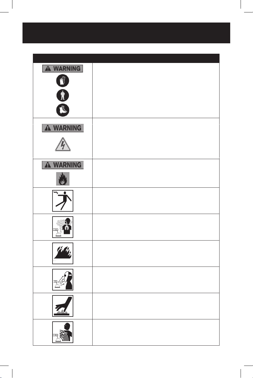
SAFETY SYMBOLS
The purpose of safety symbols is to alert you of the potential safety RISKS.
Recognize and understand them. Follow the instructions provided.
SYMBOL MEANING
Failure to obey a DANGER safety alert WILL result in serious personal
injury or death to you or to others. Always obey all messages following
this symbol to reduce the risk of serious personal injury or death.
Failure to obey a WARNING safety alert MAY result in serious personal
injury or death to you or to others. Always obey all messages following
this symbol to reduce the risk of potential serious personal injury or
death.
Failure to obey a CAUTION safety alert MAY result in personal injury
or property damage to you or to others. Always obey all messages
following this symbol to reduce the risk of personal injury or
property damage.
Failure to obey a NOTICE or a CAUTION (without a safety alert)
MAY result in property damage to you or to others. Always obey all
messages following this symbol to reduce the risk of property damage.
ALWAYS WEAR EYE PROTECTION THAT CONFORMS WITH CSA
Z94.3 or ANSI SAFETY STANDARD Z87.1
FLYING DEBRIS can cause permanent eye damage. Prescription
eyeglasses ARE NOT a replacement for proper eye protection. The
usage of a safety standard compliant face shield placed over proper
safety glasses or goggles can reduce the risk of facial injury.
Non-compliant eyewear can cause serious injury if broken during
the operation of a power tool.
Use hearing protection, particularly during extended periods of
operation of the tool, or if the operation is noisy.
WEAR A DUST MASK THAT IS DESIGNED TO BE USED WHEN
OPERATING A POWER TOOL IN A DUSTY ENVIRONMENT.
1150-003
INVERTER MULTI-PROCESS WELDER KIT
4
SYMBOL MEANING
Always wear non-slip gloves that fit properly to protect your hands
and to help you grip the tool.
Always wear sturdy clothing with long sleeves and long pants.
Never operate the tool while wearing shorts, short sleeve shirt or
while shirtless.
Always wear non-slip safety boots to prevent foot injuries and slipping
that could cause loss of control of the tool.
To avoid electrical hazards, fire hazards or damage to the tool,
use proper circuit protection.
WARNING: Ventilation openings in batteries and chargers must
always be open to allow cooling air to circulate freely. Air vents that
are blocked, restricted or covered may result in the battery or charger
overheating. Overheating may lead to damage to the tool or cause a
fire, resulting in possible serious injury.
ELECTRIC SHOCK CAN KILL
FUMES AND GASES
FIRE HAZARDS
ARC RAYS
HOT MATERIALS
MAGNETIC FIELDS
This machine is wired at the factory for 120V and 230V AC operations
(Plug will only fit one way). Plug the power cord into a properly
grounded, GFCI protected 120VAC or 230V AC receptacle that
matches the plug. The circuit must be equipped with delayed action-
type circuit breaker or fuses. To avoid shock or fire, replace power cord
immediately if it is worn, cut or damaged in any way

5
GENERAL SAFETY INSTRUCTIONS
WARNING: OWNER’S MANUAL.
Read and understand this owner’s manual BEFORE using machine.
TRAINED OPERATORS ONLY. Untrained operators have a higher risk of being hurt
or killed. Only allow trained/supervised people to use this machine. When machine
is not being used, dis- connect power, remove switch keys, or lock-out machine to
prevent unauthorized use - especially around children. Make your workshop kid
proof!
DANGEROUS ENVIRONMENTS. Do not use machinery in areas that are
wet, cluttered, or have poor lighting. Operating machinery in these areas greatly
increases the risk of accidents and injury.
MENTAL ALERTNESS REQUIRED. Full mental alertness is required for safe
operation of machinery. Never operate under the influence of drugs or alcohol,
when tired, or when distracted.
ELECTRICAL EQUIPMENT INJURY RISKS. You can be shocked, burned, or
killed by touching live electrical components or improperly grounded machinery.
To reduce this risk, only allow qualified service personnel to do electrical
installation or repair work, and always disconnect power before accessing or
exposing electrical equipment.
DISCONNECT POWER FIRST. Always disconnect machine from power supply
before making adjustments, changing tooling, or servicing machine. This prevents
an injury risk from unintended startup or contact with live electrical components.
EYE PROTECTION. Always wear ANSI-approved safety glasses or a face shield
when operating or observing machinery to reduce the risk of eye injury or blindness
from flying particles. Everyday eyeglasses are NOT approved safety glasses.
WEARING PROPER APPAREL. Do not wear clothing, apparel or jewelry that
can become entangled in moving parts. Always tie back or cover long hair. Wear
non-slip footwear to reduce risk of slipping and losing control or accidentally
contacting cutting tool or moving parts.
HAZARDOUS DUST. Dust created by machinery operations may cause cancer,
birth defects, or long-term respiratory damage. Be aware of dust hazards
associated with each workpiece material. Always wear a NIOSH-approved
respirator to reduce your risk.
HEARING PROTECTION. Always wear hearing protection when operating or
observing loud machinery. Extended exposure to this noise without hearing
protection can cause permanent hearing loss.
REMOVE ADJUSTING TOOLS. Tools left on machinery can become dangerous
projectiles upon startup. Never leave chuck keys, wrenches, or any other tools on
machine. Always verify removal before starting!
USE CORRECT TOOL FOR THE JOB. Only use this tool for its intended purpose
- do not force it or an attachment to do a job for which it was not designed. Never
make unapproved modifications—modifying tool or using it dierently than
intended may result in malfunction or mechanical failure that can lead to personal
injury or death!

1150-003
INVERTER MULTI-PROCESS WELDER KIT
6
AWKWARD POSITIONS. Keep proper footing and balance at all times when
operating machine. Do not overreach! Avoid awkward hand positions that make
workpiece control dicult or increase the risk of accidental injury.
CHILDREN & BYSTANDERS. Keep children and bystanders at a safe distance
from the work area. Stop using machine if they become a distraction.
GUARDS & COVERS. Guards and covers reduce accidental contact with moving
parts or flying debris. Make sure they are properly installed, undamaged, and
working correctly before operating machine.
FORCING MACHINERY. Do not force machine. It will do the job safer and better at
the rate for which it was designed.
NEVER STAND ON MACHINE. Serious injury may occur if machine is tipped or if
the cutting tool is unintentionally contacted.
STABLE MACHINE. Unexpected movement during operation greatly increases risk
of injury or loss of control. Before starting, verify machine is stable and mobile base
(if used) is locked.
USE RECOMMENDED ACCESSORIES. Consult this owner’s manual or the
manufacturer for recommended accessories. Using improper accessories will
increase the risk of serious injury.
UNATTENDED OPERATION. To reduce the risk of accidental injury, turn machine
OFF and ensure all moving parts completely stop before walking away. Never leave
machine running while unattended.
MAINTAIN WITH CARE. Follow all maintenance instructions and lubrication
schedules to keep machine in good working condition. A machine that is improperly
maintained could malfunction, leading to serious personal injury or death.
DAMAGED PARTS. Regularly inspect machine for damaged, loose, or misaligned
parts - or any condition that could aect safe operation. Immediately repair/replace
before operating machine. For your own safety, DO NOT operate machine with
damaged parts!
MAINTAIN POWER CORDS. When disconnect- ing cord-connected machines
from power, grab and pull the plug—NOT the cord. Pulling the cord may damage
the wires inside. Do not handle cord/plug with wet hands. Avoid cord damage by
keeping it away from heated surfaces, high trac areas, harsh chemicals, and wet/
damp locations.
SERVICE
• Have your machinery serviced by a qualified repair person using only identical
replacement parts. This will ensure that the safety of the machinery is
maintained.

7
SPECIFIC SAFETY RULES FOR INVERTER MIG/
FLUX/STICK WELDER
WARNING: In order to avoid mistakes that could cause serious injury, read the
following steps carefully and understand them thoroughly before using this welder.
WELDING FUMES. Breathing welding fumes can cause suocation or poisoning
without warning. Keep your head out of welding fumes. Use adequate ventilation at
the arc to safely remove the fumes from your breathing zone and the general area.
Use ANSI approved respirators for the type of welding operation. Protect others
from these fumes.
WELDING IN A CONFINED SPACE CAN BE HAZARDOUS. Always open all
covers, sustain forced ventilation, remove toxic and hazardous materials, and
provide a power disconnect to the welder inside the workspace. Always work with
someone who can give you help from outside the space. Welding can displace
oxygen. Always check for safe breathing atmosphere and provide air-supplied
respirators if necessary. Keep in mind that all normal welding hazards are intensified
in a confined space.
ELECTRIC SHOCK. DO NOT touch live electrical parts. Connect welder to power
source with approved earth ground. Make sure all electrical connections are tight,
clean, and dry. Connect workpiece to approved earth ground. The work lead is NOT
a ground connection and is to be used only to complete the working welding circuit.
PREVENT FIRES. Welding work zones must be kept clear of flammable liquids,
such as gasoline and solvents; combustible solids, such as paper and wood; and
flammable gases, such as acetylene and hydrogen. Provide approved fire barriers
and fire extinguishing equipment for the welding zone. Stay alert for sparks and
spatter thrown into cracks and crevices that can start a smoldering fire. Inspect the
work area again one hour after welding for any potential fire hazards.
WORKING AREA. Keep working area clear of any material not involved in the
welding operation. Keep all equipment, workpieces, and work surfaces clean, dry,
and free of entanglements. Keep lead cables organized and away from your body.
PROTECT BODY FROM ARC BURNS, SPARKS, AND SPATTER. Wear correct
and approved eye, ear, and body protection. Wear complete body protection, such
as clean and oil-free protective clothing, leather gloves, protective cap, heavy long-
sleeve shirt, cuess pants, and high leather boots. DO NOT wear jewellery or frayed
clothing. Use a welding helmet with the correct shade of filter for the operation.
Protect other people and property in your working zone from exposure to arc
radiation, sparks, and spatter.
HANDLING GAS CYLINDERS. Regardless of content, pressurized gas cylinders
can explode. Always secure a protector cap in place over the outlet valve assembly
when moving the cylinder. A broken o valve could release the pressurized contents
and cause the cylinder to be hurled about at dangerously high speeds, causing
serious property damage, personal injury, or death. Always use safe methods when
moving gas cylinders. Always secure a gas cylinder to a wall or approved cylinder
cart with a chain before using or storing.
PROTECT GAS CYLINDERS FROM HEAT OR DAMAGE. An excess of heat can
cause the pressurized gas to expand and explode the cylinder. Never weld on the

1150-003
INVERTER MULTI-PROCESS WELDER KIT
8
gas cylinder. Damaging the outside of the cylinder can cause the cylinder to crack
and explode. Exploding pressurized gas cylinders can cause serious property
damage, personal injury, or death.
ELECTRIC AND MAGNETIC FIELDS (EMF). Welding operations create EMF
around the welding equipment and workpieces. Workers who have pacemakers
must consult with their physician before using this equipment or being within 50
feet of welding operations.
EXPERIENCING DIFFICULTIES. If you are experiencing diculties performing the
intended operation, stop using the equipment.
Keep the environment you will be welding in free from flammable materials.
Always keep a fire extinguisher accessible to your welding environment.
Always have a qualified person install and operate this equipment.
Make sure the area is clean, dry and ventilated. Do not operate the welder in humid,
wet or poorly ventilated areas.
Always have your welder maintained by a qualified technician in accordance with
local, provincial and national codes.
Always be aware of your work environment. Be sure to keep other people, especially
children, away from you while welding.
Check all components to ensure they are clean and in good operating condition
before use.
Do not operate the welder if the output cable, wire, or any part of the system is wet.
Do not immerse them in water.
Do not allow any body part to come in contact with the wire if you are in contact with
the material being welded, ground or wire from another welder.
Do not weld if you are in an awkward position. Always have a secure stance while
welding to prevent accidents. Wear a safety harness if working above ground.
Do not drape cables over or around your body.
Wear a full-coverage helmet with shade (see ANSI Z87.1 safety standard)
and safety glasses while welding.
Wear proper gloves and protective clothing to prevent your skin from being exposed
to hot metals, UV and IR rays.
Do not overuse or overheat your welder.
Allow proper cooling time between duty cycles.
Always use this welder in the rated duty cycle to prevent excessive heat and failure.
Do not attempt to repair or maintain the welder while the power is on.
Do not touch the electrode and the ground or grounded work piece at the same time.
Do not use a welder to thaw frozen pipes.
SAVE THIS USER MANUAL
WARNING:
MISUSE or failure to follow the safety rules stated in this instruction manual
may cause serious personal injury.
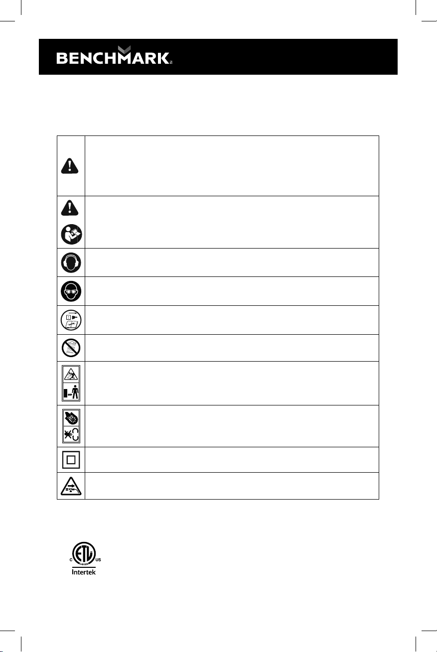
9
SAFETY SYMBOLS
The rating plate on your tool may show symbols. These represent important
information about the product or instructions on its use.
WARNING: Please read all of the safety and operating instructions
carefully before using this tool. Please pay particular attention to all
sections of this User Guide that carry warning symbols and notices. Some
of the following symbols may be used on this tool.
Observe caution and safety notes.
To reduce the risk of injury, user must read and understand User Guide
before using this tool.
Wear ear protection.
Wear protective helmet and eye protection.
Switch o and remove plug from power source before cleaning or
maintenance.
Do not use in the rain or leave outdoors while it is raining.
Keep bystanders away.
Don’t touch the inlet and outlet when the vacuum cover is opened or the
tube is removed.
Double insulation.
Remove plug from the power source immediately if the power cord is
damaged or cut.
This symbol designates that this tool is listed with Canadian and U.S.
requirements by CSA
Conforms to ANSI/IEC 60974-1; CSA E60974-1
4009939
MIG-200
1150-003
INVERTER MULTI-PROCESS WELDER KIT
10
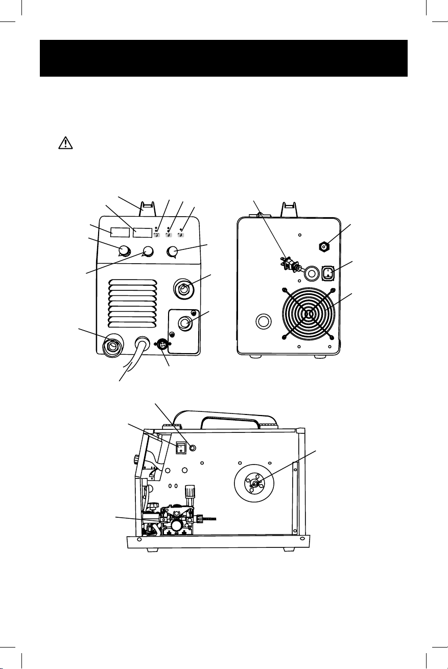
KNOW YOUR BENCHMARK INVERTER
MULTI-PROCESS WELDER
Front View Rear View
Side View
1
2
3
4
5
6
7
22
21
13
12
11
10
9
8
14
16
15
17
18
19
20

11
FUNCTIONS
1 Handle
2 Welding voltage meter
3 Welding current meter
4 Regulator - wire feeding speed (MIG mode), welding current (MMA mode)
5 Regulator - welding voltage (MIG mode)
6 Positive output connector
7 Polarity switching cable
8 MIG/MMA mode selector
9 2T/4T mode selector
10 Gas test
11 Inductor adjustment (MIG mode), arc force (MMA mode)
12 Negative output connector
13 MIG welding torch connector
14 Gas supply inlet
15 Power switch
16 Power input cable and plug
17 Fan
18 Quick wire feeding button
19 Wire feeder
20 Wire spool mount spindle
21 Spool gun/MIG gun switch
22 Wire feed control socket
GAS & NOGAS Application connection:
Gas application (using solid cored welding wire: polarity switching cable connects
“+”, earth clamp connects “-”, torch connect to “ ” and fasten it.
No gas application (using flux cored welding wire: polarity switching cable connects
“-”, earth clamp connects “+”, torch connect to “ ” and fasten it.
Note: Inductor adjustment is to set the welding arc force, 0 is standard setting
value.
If the code “E01” is shown on the display, it means the machine is over heated
and under protection, please wait till the display “E01” is o.

1150-003
INVERTER MULTI-PROCESS WELDER KIT
12
POWER SUPPLY
Before installing the machine, consider
the availability and proximity of the
required power supply circuit. If an
existing circuit does not meet the
requirements for this machine, a new
circuit must be installed. To minimize the
risk of electrocution, fire, or equipment
damage, installation work and electrical wiring must be done by an electrician or
qualified service personnel in accordance with all applicable codes and standards.
FULL-LOAD CURRENT RATING
The full-load current rating is the amperage a machine draws at 100% of the rated
output power. On machines with multiple motors, this is the amperage drawn by the
largest motor or sum of all motors and electrical devices that might operate at one
time during normal operations.
Full-Load Current Rating at 230V ..... 17.5 Amps
Full-Load Current Rating at 120V...... 17.5 Amps
The full-load current is not the maximum amount of amps that the machine will
draw. If the machine is overloaded, it will draw additional amps beyond the full-
load rating. If the machine is overloaded for a sucient length of time, damage,
overheating, or fire may result— especially if connected to an undersized circuit. To
reduce the risk of these hazards, avoid over- loading the machine during operation
and make sure it is connected to a power supply circuit that meets the specified
circuit requirements.
CIRCUIT INFORMATION
A power supply circuit includes all electrical equipment between the breaker box
or fuse panel in the building and the machine. The power supply circuit used for
this machine must be sized to safely handle the full-load current drawn from the
machine for an extended period of time. (If this machine is connected to a circuit
protected by fuses, use a time delay fuse marked D.)
CAUTION!
For your own safety and protection of property, consult an electrician if you are
unsure about wiring practices or electrical codes in your area.
Note: Circuit requirements in this manual apply to a dedicated circuit—where only
one machine will be running on the circuit at a time. If machine will be connected to
a shared circuit where multiple machines may be running at the same time, consult
an electrician or qualified service personnel to ensure circuit is properly sized for
safe operation.
CIRCUIT REQUIREMENTS FOR 230V
This machine is prewired to operate on a power supply circuit that has a verified
ground and meets the following requirements:

13
Nominal Voltage ..................... 208V, 220V, 230V, 240V
Cycle ...................................................................60 Hz
Phase .......................................................Single-Phase
Power Supply Circuit....................................... 50 Amps
Plug/Receptacle ......................................... NEMA 6-50
CIRCUIT REQUIREMENTS FOR 115V ADAPTOR
This machine can be converted to operate on a power supply circuit that has
a verified ground and meets the requirements listed below. (Refer to Voltage
Conversion instructions for details.)
Nominal Voltage ...............................110V, 115V, 120V
Cycle ...................................................................60 Hz
Phase .......................................................Single-Phase
Power Supply Circuit....................................... 20 Amps
Plug/Receptacle ......................................... NEMA 5-15
GROUNDING REQUIREMENTS
This machine MUST be grounded. In the event of certain malfunctions or
breakdowns, grounding reduces the risk of electric shock by providing a path of
least resistance for electric current. This machine is equipped with a power cord
that has an equipment-grounding wire and a grounding plug. Only insert plug into a
matching receptacle (outlet) that is properly installed and grounded in accordance
with all local codes and ordinances. DO NOT modify the provided plug! Improper
connection of the equipment-grounding wire can result in a risk of electric shock.
Figure 2. Typical 5-15 plug and receptacle.
Grounding Pin
Neutral Hot
5-15 PLUG
GROUNDED
5-15 RECEPTACLE
Figure 1. NEMA 6-50 plug and receptacle.
Grounding Prong
Current Carrying Prongs
6-50 GROUNDED
RECEPTACLE
6-50
PLUG

1150-003
INVERTER MULTI-PROCESS WELDER KIT
14
The wire with green insulation (with or without yellow stripes) is the equipment-
grounding wire. If repair or replacement of the power cord or plug is necessary, do
not connect the equipment-grounding wire to a live (current carrying) terminal.
Check with a qualified electrician or service personnel if you do not understand
these grounding requirements, or if you are in doubt about whether the tool is
properly grounded. If you ever notice that a cord or plug is damaged or worn,
disconnect it from power, and immediately replace it with a new one.
WARNING
Serious injury could occur if you connect machine to power before completing setup
process. DO NOT connect to power until instructed later in this manual.
EXTENSION CORDS
We do not recommend using an extension cord with this machine. If you must use
an extension cord, only use it if absolutely necessary and only on a temporary basis.
Extension cords cause voltage drop, which can damage electrical components and
shorten motor life. Voltage drop increases as the extension cord size gets longer and
the gauge size gets smaller (higher gauge numbers indicate smaller sizes).
Any extension cord used with this machine must be in good condition and contain a
ground wire and matching plug/receptacle. Additionally, it must meet the following
size requirements:
Minimum Gauge Size ........................................12 AWG
Maximum Length (Shorter is Better)......................50 ft.
ELECTRODE SELECTION
The welding electrode is a rod coated with a layer of flux. When welding, electrical
current flows between the electrode (rod) and the grounded metal workpiece.
The intense heat of the arc between the rod and the grounded metal melts the
electrode and the flux. The most popular electrodes are:
— E6013 60,000 PSI tensile strength used for poor fit-up applications.
— E7014 70,000 PSI tensile strength used for high deposition and fast travel
speeds with light penetration.
— E7018 70,000 PSI tensile strength
This welder is capable of welding with solid core or flux cored wire 0.024" (0.6mm),
0.030" (0.8mm) or 0.035" (.9mm); accomodates 1 kg or 5kg wire spools both on
120V and 230V.
On 120V, this welder is capable of welding with stick wire 1/16" - 3/32" (1.6-2.5mm)
and on 230V is capable of the stick wire 1/16" - 5/32" (1.6-4mm)

15
ASSEMBLY
Wire Spool Installation/Wire Setup
1. Turn the power Switch OFF and unplug the Welder before proceeding.
2. Pull up on the Door Latch, then open the Door.
3. 1-2 pound Wire Spool installation: Remove the Wingnut, spring and washers.
If replacing a Spool, remove the old Spool and all remaining wire from the liners.
4. Place the new Wire Spool over the Spool Spindle and against the Spool Brake
Pad as illustrated. to prevent wire feed problems, set the Spool so that it will
unwind clockwise.
5. Replace the Spacer over the Spool Spindle and secure Spool in place with the
Wingnut.
Spring
Washer
Big Washer

1150-003
INVERTER MULTI-PROCESS WELDER KIT
16
NOTICE: If Wire Spool can spin freely, Wingnut is too loose. This will cause
the welding wire to unravel and unspool which can cause tangling and feeding
problems.
6. 10-12 pound Wire Spool installation: Remove
the Wingnut, spring and washers. If replacing
a Spool, remove the old Spool and all
remaining wire from the liners.
7. Place the Spool Adapter over the Spool
Spindle and against the Spool Brake Pad as
illustrated.
8. Place the new Wire Spool over the Adapter
and line up pin on Adapter with hole in Spool.
to prevent wire feed problems, set the Spool
so that it will unwind clockwise.
9. Replace the Spacer over the Spool Spindle
and secure Spool in place with the Wingnut.
NOTICE: This will cause the welding wire to unravel and unspool which can cause
tangling and feeding problems.
10. Screw the Spool Knob into the Spool Adapter.
11.Turn the Feed Tensioner knob counterclockwise to loosen it enough to pull it
down to remove tension. The spring-loaded Idler Arm will move up as shown.

17
12.Feed Roller instructions:
Check that the Feed Roller
is correct for the type of wire
being used (solid core or flux-
cored) and that it is turned to
properly match the wire size
marked on the Wire Spool:
a. Unscrew the Feed Roller Knob
counterclockwise.
b. Remove the Feed Roller Knob
to expose the Feed Roller.
c. Flip or replace the Feed Roller
as needed and confirm that it
is the correct Roller for the type
of wire being used and that the
number showing is the same
as the wire diameter on the
Spool.
d. Screw the Feed Roller Knob
back into place to secure the
Feed Roller.

1150-003
INVERTER MULTI-PROCESS WELDER KIT
18
13.Loosen the Knob on the Wire
Feed mechanism, then insert
the Gun Cable Connector
through the hole on the Welder
front and into the socket on the
Wire Feed.
14.Ensure that the Gun Cable
Connector is fully inserted into
the socket on the Wire Feed
mechanism as shown, then
tighten the Knob securely. If
Connector is not fully inserted,
the gas connection will leak,
preventing shielding gas from
reaching the welding arc.
NOTICE: To prevent damage,
do not overtighten the Knob.
15.Insert the Wire Feed Control
Cable into the socket on the
welder front, then tighten the
lock ring on the Cable plug.
Note that the plug on the
Cable fits into the Socket in
one specific orientation only.
16. DCEN direct current
Electrode negative Wire
Setup for Flux-cored
(gasless) welding:
Plug Ground Clamp Cable
into Positive (+) Socket.
Plug polarity switch cable
into Negative (–) Socket.
Twist cables clockwise all
the way to lock in place.
polarity
switch cable

19
17.DCEP Direct Current Electrode Positive Wire
Setup for Solid Core (gas shielded) welding:
a. Plug Ground Clamp Cable
into Negative (–) Socket.
Plug polarity switch cable
into Positive (+) Socket.
Twist cables clockwise all
the way to lock in place.
b. Determine which type of
shielding gas would be
appropriate for the welding you
will do. Refer to the Settings
Chart on the inside of the
Welder door.
c. With assistance, set the
cylinder (not included) onto
a cabinet or cart near the
Welder and secure the cylinder
in place with two straps (not
included) to prevent tipping.
d. Remove the cylinder’s cap.
Stand to the side of the valve
opening, then open the valve
briefly to blow dust and dirt
from the valve opening. Close
the cylinder valve.
e. Locate the Regulator
(included) and close its valve
until it is loose, then thread
Regulator onto cylinder and
wrench-tighten connection.
NOTE: When using C100
shielding gas, connect the
enclosed CGA 580/320
adapter to the inlet connection
of the Regulator and wrench-
tighten. Thread the adapter
onto the gas cylinder and
wrench-tighten.
f. Attach the Gas Hose (not included)
to the Regulator’s outlet and
the Welder’s gas inlet. Wrench-
tighten both connections.
Table of contents
Popular Welding System manuals by other brands

ESAB
ESAB Warrior 400i CC/CV instruction manual

Trafimet
Trafimet PW 180 user manual

Lincoln Electric
Lincoln Electric INVERTEC V205-T AC/DC TIG Operator's manual

Miller
Miller Dynasty 400 owner's manual

HSS Hire
HSS Hire Hire-Weld HW024 Operating & safety guide

Pro-Weld
Pro-Weld CD-212 Operation & maintenance manual

Lincoln Electric
Lincoln Electric RED-D-ARC LN-25 PRO EXTREME Operator's manual

WELDY
WELDY sealer GW800 operating manual

IVT
IVT PW-900 instruction manual

EINHELL
EINHELL TC-GW 190 D Original operating instructions

Draper
Draper AW105T instruction manual

Miller Electric
Miller Electric Big Blue 502P owner's manual


