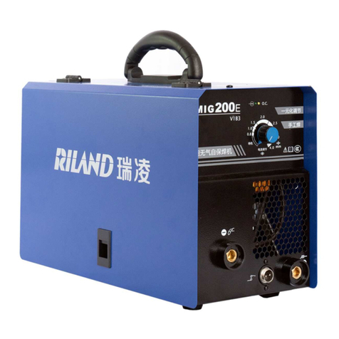
Riland MMA 120GDM User manual

USER MANUAL
MMA 120GDM/140GDM/160GDM

USER MANUAL - 0 - YF-29C A3

CONTENTS
SAFETY WARNING....................................................................................................................................3
PRODUCT DESCRIPTION.........................................................................................................................8
TECHNICAL PARAMETERS......................................................................................................................9
INSTALLATION INSTRUCTION................................................................................................................10
PANEL FUNCTION ILLUSTRATION.........................................................................................................13
OPERATION PARAMETER RECOMMENDATION...................................................................................16
CIRCUIT DIAGRAM...................................................................................................................................17
ATTENTIONS PREVENTIVE MEASURES............................................................................................18
POTENTIAL OPERATING PROBLEMS....................................................................................................20
DAILY MAINTENANCE..............................................................................................................................21
TROUBLESHOOTING AND FAULT FINDING..........................................................................................22
DAILY CHECKING.....................................................................................................................................23
USER MANUAL - 1 - YF-29C A3

USER MANUAL - 2 - YF-29C A3

SAFETY WARNING
● Please read this man al caref lly before sing it.
● The safety notes listed in this man al is to ens re correct se of the machine and to keep yo and
other people from being h rt.
● The machine is safety considered designed, please refer to the safety warning listed in the man al
when sing it in case of bad accidents.
● Wrong se of the machine will ca se different extent of h rt as follows, and there will be warning sign
and description for remind.
Warning
sign
Description Meaning
High-danger “High-danger” means there is possibility of severe dangero s, and
may ca se dead if not avoid. This sign is sed in extreme case, which
is normally related to body dangero s neither than property loss.
Danger “Danger” means there is possibility of dangero s sit ation, and may
ca se badly h rt if not avoid. It can also refer to property loss.
Notes This means it may ca se body h rt if not avoid. Please refer to the
related description when this sign occ rred.
Danger! Please follow the rules below in case of bad accidents:
1. Do not se the machine in none-welding areas.
2. The machine is safety considered designed, please do read the warning notes caref lly in case of
dead or other bad accidents.
3. Follow related reg lations for the constr ction of the inp t drive force, selection of the set p place,
sage of the high-press re gas, storage and config ration, safe-keeping of the workpiece after
welding and management of the offal etc.
4. No entry of nrelated person to the welding area.
5. People sing heart pacemaker cannot get close to the welding machine and area witho t the doctor’s
permit. The magnetism ca sed when connecting the machine will ca se infl ence to the pacemaker.
6. Ask profession person to install, check and maintain the machine.
7. Please correctly nderstand the contents of this man al to ens re safety, and ask those professional
USER MANUAL - 3 - YF-29C A3

people with safety knowledge and techniq e to operate the machine.
Danger! Please follow the rules below in case of electric shock:
*Any contact of electric parts may cause fatal electric shock or burnt.
1. Don’t to ch any electric parts.
2. Ask professional person to connect the machine and workpiece to the gro nd.
3. C t off the power box before the installation or checking, and restart after 5 min tes. For the
capacitance is chargeable, please ens re it has no voltage before restart even if the power so rce is
c t off.
4. Do not se cable witho t eno gh section or with worn-o t cover or broken cond ctor.
5. Do ens re ins lation at the cable joint parts.
6. Do not se the machine when the ho sing is off.
7. Do not se broken or wet ins lation gloves.
8. Use safety net when work at high position.
9. Check and maintain reg larly, don’t se it ntil the broken parts are fixed well.
10. C t off all the inp t power when not se.
11. Follow the national or local related standard and reg lations when sing the AC/DC machine at
narrow or high position.
Danger! Please use preventive measures to avoid gas and fumes.
*Gas and fumes are harmful to health.
*It may cause choke when operate in narrow space.
1. In case of accidents like gas poisoning or choke, please se s ggested exha st eq ipment and
breathe preventive facilities.
2. In case of h rt and poisoning by gas and other powder, please se s ggested part exha st
eq ipment and breathe preventive facilities.
3. When operated on tr nks, boilers, cabins etc.,the CO2 and argon gas will stay in the bottom. Please
replace gas s fficiently and se gas respire facilities in case of oxygen shortage.
4. Please accept the s pervisor’s check when operate in narrow space, and ens re eno gh gas s pply
and se breathe preventive facilities.
5. Do not weld in degrease, washing and spray space.
6. Use breathe preventive facilities as it will ca se poisono s d st and gas when weld shielded steel.
USER MANUAL - 4 - YF-29C A3

Danger! Please follow the below notes to avoid accidents like fire and explode:
*Spark and hot workpiece can cause fire.
*It may cause fire if the cable is not connected well or when the current circuit
of the steel or other workpiece are not connected completely.
*Do not weld on the case of tinder stuff, or it may cause explode.
*Do not weld airtight containers such as slot, pipe etc., or may break.
1. Do not p t tinder st ff in welding area.
2. Do not weld aro nd tinder gas.
3. Do not p t heat workpiece near the tinder st ff.
4. When weld the dooryard, gro nd and wall, do move away the tinder st ff aro nd.
5. The cable joint place sho ld be ins lated.
6. The cable joint of the workpiece sho ld be close eno gh to the welding place.
7. Do not weld those facilities with gas pipe or airtight slot.
8.P t fire exting isher aro nd the welding area in case of fire.
Notes! Please wear protective appliance to avoid arc, spark, residue and noise.
* Arc ray can cause eye inflammation or skin burnt.
*Spark and residue will burn your eyes and skin.
1. When welding or s pervise welding, please se preventive facilities with eno gh shielding.
2. Please wear preventive glasses.
3. Please wear preventive facilities s ch as leather gloves, coat, foot-safeg ard and apron.
4. Set preventive shield screen aro nd the welding area to protect other people from harmf l arc rays.
Notes! Please follow the below notes to avoid gas cylinder toppling over or broken.
*Toppling over of the gas cylinder will cause body hurt.
* Wrong use of the gas cylinder will lead to high-pressure gas eruption and
cause human hurt.
1. Use the gas cylinder correctly.
2. Use the eq ipped or recommended gas adj stment.
3. Read the man al of the gas adj stment caref lly before sing it, and pay attention to the safety
notes.
4. Fix the gas cylinder with appropriate holder and other relative parts.
USER MANUAL - 5 - YF-29C A3
5. Do not p t the cylinder nder high temperat re and s nshine.
6. Do not p t yo r face close to the gas cylinder exit when opening it.
7. P t on the gas shield when not se.
8. Do not p t the torch on the gas cylinder or to ch the electrode.
Notes! Any touch of the switch part will cause injury, please pay attention to the below
notes:
* Do not put fingers, hair, clothes etc. near to the moving parts such as the fan.
1. Do not se the machine when the ho sing is off.
2. Ask professional person to install, operate, check and maintain the machine.
3. Do not p t fingers, hair, clothes etc. near to the switch parts s ch as the fan.
Notes! Follow the below note as the wire end may cause body hurt:
*The wire shoot out from the torch can stab eyes, face and other naked parts.
1. Before feeding the wire, do not look into the electric cond ction hole, or the wire shooted o t may
stab yo r eyes and face.
2. When feeding the wire man ally or press the torch, do not p t the torch end near to yo r eyes, face
and other naked parts.
Notes! Follow the below notes to ensure better work efficiency and power source:
*No person under of in front of the machine when swing in case of injury!
1. Preca tions against toppling over.
2. Warning against the se of welding power so rce for pipe thawing.
3. Lift the power so rce from two sides when se the p-down forklift tr ck in case of toppling over.
4. When sing the crane for lift, tie the rope to the ears with an angle no more than φ15 to the vertical
direction.
5. If the machine is eq ipped with gas cylinder and wire feeder, download them from the power so rce
and ens re the horizontal of the machine. Do fix the gas cylinder with gall s or chain when moving it
in case of body h rt.
6. Ens re fastness and ins lation when sing the swing ring to lift the wire feeder in welding.
7. If the machine is eq ipped with gall s or handles, they are only for hands not for crane, fork-lift tr ck
or other swing eq ipments.
USER MANUAL - 6 - YF-29C A3

Notes for electromagnetism disturb:
1. It may need extra preventive meas res when the power is sed in some partial space.
2. Before the installation, please estimate the potential electromagnetism problems of the environment
as follows:
1) Upper and down parts of the welding eq ipments and other nearby power cable, control cable,
signal cable and phone cable.
2) Wireless electric as well as TV radiation and reception eq ipment.
3) Comp ter and other control eq ipments.
4) Safety-recognition eq ipment etc. Eg: s pervise of ind strial eq ipments.
5) Health conditions of the people aro nd. Eg: se of the heart pacemaker and a diphone.
6) Eq ipments for adj stment and meas rement.
7) Anti-dist rb capability of other sed eq ipments .Users sho ld ens re these eq ipments and the
environment are compatible, and this may need extra preventive meas res.
8) Practical state of the welding and other activities.
3. Users sho ld follow the below notes to decrease radiation dist rb:
1) Connect the welding eq ipments to the power s pply lines.
2) Maintain the welding eq ipments reg larly.
3) The cable sho ld be short eno gh to be close to each other and near to the gro nd.
4) Ens re the safety of all the metal parts and other parts nearby.
5) The workpiece sho ld be well connected to the gro nd.
6) Shield or protect the other cable and eq ipments to decrease the infl ence of dist rb. The welding
eq ipments can be f lly shielded nder special conditions.
4. Users are responsible for the dist rb problems ca sed by welding.
USER MANUAL - 7 - YF-29C A3

PRODUCT DESCRIPTION
MMA 120GDM/140GDM/160GDM,with its MMA and LIFT TIG f nction, is a m lti-f nction welding
machine that applies the most advanced inversion technology in the world.
The appearance of the invert TIG machine comes after the appearance of invert power theory and
parts. The principle of inversion is to transform the power freq ency of 50Hz/60Hz into direct c rrent
and invert it into high freq ency (33KHz) thro gh high-power device IGBT, then perform voltage-drop
and comm tation with the o tp t high-power D.C power s pply via f ll digital P lse Width Mod lation
(PWM) control technology. Since the switch power inversion technology is adopted, the weight and
vol me decrease greatly while the conversion efficiency increase for more than 30%
O r welding power so rce can offer stronger, more concentrated and more stable arc. When the
welding rod and work piece get short circ it, its response will be q icker. It means that it is easy to
design welding machine with different dynamic characteristics, and it can even adj st the
characteristics to make arc softer or harder.
Under MMA mode, the characteristic of the machine is slope, and has VRD f nction. The welding
c rrent, p sh c rrent and heat arc initiation c rrent se the same knob for synergic adj stment. And
with good arc initiation and stable power o tp t, the welding gap and q ality can reach the best effect.
Under TIG mode, the arc initiation is easy, and the arc is concentrated.
The machine, with small vol me, light weight and stable characteristic, can weld stainless steel, carbon
steel, copper and other color metal. Its transfer efficiency is above 85%.
Thanks for p rchasing o r prod cts and looking forward to yo r precio s advice, we will try o r best to
perfect o r prod cts and service
WARNING!
The machine is mainly used for industrial purpose. It will cause radio interference
indoor, operators shall take fully preventative measures.
USER MANUAL - 8 - YF-29C A3

TECHNICAL PARAMETERS
Type
Item
MMA120GDM MMA 140GDM MMA 160GDM
Power voltage (V) 1 phase
230V15%
1 phase
230V15%
1 phase
230V15%
Freq ency (Hz) 50/60 50/60 50/60
Rated inp t c rrent (A) 23.2 28 32
O tp t c rrent adj stment (A) 40-120(MMA)
20-120(TIG)
40-140(MMA)
20-140(TIG)
40-160(MMA)
20-160(TIG)
O tp t voltage (V) 21.6-24.8(MMA)
10.8-14.8(TIG)
21.6-25.6(MMA)
10.8-15.6(TIG)
21.6-26.4(MMA)
10.8-16.4(TIG)
2520No-load voltage(V) 64 64 64
Power factor 0.73 0.73 0.73
D ty cycle (%)/ 40℃35 35 35
Efficiency (%) 80 80 80
Ins lation grade F F F
Ho sing protection grade IP21S IP21S IP21S
Weight (kg) 4.8 4.8 4.8
Overall dimension (mm) 288*136*234 288*136*234 288*136*234
USER MANUAL - 9 - YF-29C A3

INSTALLATION INSTRUCTION
The welding eq ipment is eq ipped with power voltage compensation device. It keeps the machine
work normally when power voltage fl ct ating ±15% of rated voltage.
When sing long cable, in order to red ce voltage drop, big section cable is s ggested. If the cable is
too long, it will affect the performance of arcing and other system f nction, it is s ggested to se the
recommend length.
1. Make s re the intake of the machine is not covered or blocked to avoid the malf nction of the
cooling system.
2. Use gro nd cable whose section no less than 6mm2 to connect the ho sing and earth. The method
is to connect the gro nded interface in the back to the earth device, or make s re the earth end of
power interface has been reliably and independently gro nded. Both ways can be sed together for
better sec rity.
MMA 120GDM/140GDM/160GDM Installation Procedures:
1、Correct Installation of LIFT TIG:
1) Connect the shielded-gas so rce correctly. The gas s pplying ro te shall incl de gas cylinder, argon
decompression flow meter and gas pipe. The connecting parts of the gas pipe sho ld be fastened
by hose clamp or other objects, in order to prevent leakage and air-in.
2) Connect the pl g of TIG torch to “-“of the front panel, and fasten it clockwise.
3) Connect one end of the earth clamp cable to “+” of the front panel, and fasten it clockwise, the other
end clamp the work piece.
2、Correct Installation of STICK:
1) Make s re cable with electrode holder and q ick pl g connected well. Connect the q ick pl g to the
socket “-” of the machine, and fasten it clockwise tightly.
2) Connect the q ick pl g at one end of the cable into the socket “+” of the machine, and fasten it
clockwise, the other end clamps the workpiece.
3) Please pay attention to the connecting terminal, DC welding machine has two connecting ways:
positive connection and negative connection. Positive connection: holder connects with “-” terminal,
while work piece with the “+” terminal. Negative connection: work piece with the“-” terminal, holder
with the “+” terminal. Choose s itable way according to the working sit ation. If ns itable choice is
USER MANUAL - 10 - YF-29C A3

made, it will ca se nstable arc, more spatters and congl tination. If s ch problems occ r, please
change the polarity of the fastened pl g. It sho ld adopt negative connection when welding with
alkaline electrode, while positive connection when welding with acid electrode.
This procedure shall be operated by electrician!
Connect proper power cable to the distrib tion box with corresponding capacity according to the inp t
voltage and c rrent (See technical parameter table). Do not connect to the inappropriate voltage and
make s re that the difference of power s pply is within permitted range.
USER MANUAL - 11 - YF-29C A3

Explanatory drawing for Installation of MMA 120GDM/140GDM/160GDM(LIFT TIG):
Explanatory drawing for Installation of MMA 120GDM/140GDM/160GDM (STICK):
USER MANUAL - 12 - YF-29C A3
Power Supply
( 1 phase~AC230V)
Earth clamp
Connect to
ground
TIG torch
Argon cylinder
Work piece
Gas meter
Power Supply
(1 phase~AC230V)
Connect to
ground
Argon cylinder
Gas meter
Earth clamp
Workpiece
Electrode holder

PANEL FUNCTION ILLUSTRATION
Front panel instruction:
①Over-c rrent/over heat indicator light
②M ltif nctional data adj sting knob (coarse adj stment by pressing the knob and t rning it, the
reg lating range is big and speed is high; fine adj stment by t rning the knob only:, the reg lating
range is small and speed is low)
③STICK/LIFT TIG switch key
④STICK/LIFT TIG indicator
⑤Welding c rrent display
Operation Instruction:
1. The starting p display
Switch on the welding power so rce, the front panel displays as Chart 1. After the【Welding c rrent
display】(or any key or knob on front panel) flashes for 5 seconds, the machine enters into the welding
mode that saved in the last sh tdown.
Chart 1: the starting- p display interface Chart 2: display nder STICK mode
2. Operation instr ction nder STICK mode.
1) When welding stops, Press the 【STICK/LIFT TIG switch key】,the STICK indicator lights p,
and it t rns into STICK mode. The front panel displays as Chart 2.
USER MANUAL - 13 - YF-29C A3

2) 【Welding c rrent display 】 shows the preset c rrent“080A”, its nit is ampere(A),and the
c rrent adj stment range is 10A-120A for MMA 120GDM, 10A-140A for MMA 140GDM, while
10A-160A for MMA 160GDM.
3. Operation instr ction nder LIFT TIG mode.
1) When welding stops, press the【STICK/LIFT TIG switch key】,the LIFT TIG indicator lights p,
and it t rns into LIFT TIG mode, the front panel displays as Chart 3. LIFT TIG means the
t ngsten contacts the workpiece first, then press the torch switch, the arc is ignited by lifting
the torch.
2) 【Welding c rrent display 】 shows the preset c rrent“080A”, its nit is ampere(A),and the
c rrent adj stment range is 10A-120A for MMA 120GDM, 10A-140A for MMA 140GDM, while
10A-160A for MMA 160GDM.
Chart 3: display nder LIFT TIG mode
Note: The machine adopts to ched ignition way when perform welding nder TIG mode. Do make the
t ngsten contacts with the workpiece completely for abo t one second firstly (can see the
t ngsten pinpoint t rns red grad ally), then lift the torch to achieve arc initiation, or the res lt will
be bad. Welding will stop after the t ngsten and workpiece get short for 4 seconds, and will
ret rn to normal after one second. The t ngsten t rns to red then dark then back to red d ring
the process. If the arc initiation fails at the first time, please wait for a second ntil perform the
second try, or it will be hard for arc initiation. After arc initiation, make the t ngsten and
workpiece short of circ it again to avoid adhibit of the t ngsten.
4. Storage f nction
If the front panel displays less voltage as in Chart 4 after the power is c t off, the 【Welding c rrent
display】on the front panel will flash once, which means the data of the operation is saved, and will
display in the next starting- p.
5. Fan dormancy f nction
The fan is in the dormancy state when the welding machine starts welding. It won’t work normally
USER MANUAL - 14 - YF-29C A3

ntil the internal temperat re above 45°C. And it will stop working when the temperat re is less than
35°C.
Malfunction display:
Malfunction display of overheating protection
The panel displays as Chart 6 when overheating, and the 【m ltif nctional data display 】flashes
contin o sly, the machine can not work normally. Only when the temperat re of the welding machine
falls below 45℃, the overheating malf nction wo ld disappear, and the machine can work normally
witho t restarting.
Chart 4:Malf nction display of overheating protection
USER MANUAL - 15 - YF-29C A3

OPERATION PARAMETER RECOMMENDATION
1:Generally, welding current is adequate to welding electrode according with as following.
Electrode
specification
φ2.5 φ3.2 φ4.0 φ5.0
welding c rrent 70-100A 110-140A 170-230A 230-280A
2: Welding variables when use TIG.
TIG welding specifications of stainless steel as follows
Thickness
(mm)
T ngsten
diameter
(mm)
Wire diameter
(mm)
Type of b tt
joint
Welding c rrent
(A)
Gas flow
(L/min)
0.5 1.0 1.0 plain b tt
joint
35-40 4-6
0.8 1.0 1.0 wire filling 35-45 4-6
1.0 1.6 1.6 40-70 5-8
1.5 1.6 1.6 50-85 6-8
2.0 2.0-2.5 2.0 80-130 8-10
3.0 2.5-3.0 2.25 120-150 10-12
USER MANUAL - 16 - YF-29C A3

CIRCUIT DIAGRAM
USER MANUAL - 17 - YF-29C A3

ATTENTIONS PREVENTIVE MEASURES
1. Environment
1)The machine works in environment where air conditions are dry with a dampness level of max
90%.
2)Ambient temperat re sho ld be between -10 to 40 degrees centigrade.
3)Avoid welding in s nshine or raining. Avoid water entering the machine
4)Avoid welding in d st area or the environment with corrosive gas.
5)Avoid gas welding in the environment with strong airflow.
2. Safety Checkpoint
O r welding machine has a protection circ it of over voltage, over c rrent and over heat. When
voltage, o tp t c rrent and temperat re of machine are exceeding the rated standard, welding
machine will stop working a tomatically. Excessive operation nder over voltage, over c rrent or
over heat may damage the machine; operator m st pay attention to followings.
1)The working area is adequately ventilated!
The welding machine is medi m and small model. B t the r nning of the machine will also
generate high c rrents, which nat ral wind circ lation cannot satisfy its cooling demands.
Therefore, each machine has an internal fan to ens re its stable performance. Make s re the
intake is not blocked or covered, there sho ld be 0.3 meter distance from welding machine to
objects of environment. User sho ld make s re the working area is adeq ately ventilated. It is
important for the performance and the longevity of the machine.
2)Do not over load!
The operator sho ld keep an eye on max d ty c rrent (Compared to the selected d ty cycle) to
make s re that the machine working c rrent does not exceed max d ty cycle c rrent. Over-load
c rrent will damage and even b rn the machine.
If machine exceeds standard d ty cycle, it may stop working and switch to protection stat s.
The temperat re control switch is activated by over heat released nder this circ mstance.
Meanwhile, the over heat indicator lights p. Under this sit ation, yo do not need to p ll o t the
USER MANUAL - 18 - YF-29C A3
This manual suits for next models
2
Table of contents
Other Riland Welding System manuals

Riland
Riland MIG 135E User manual

Riland
Riland ARC 315GTS User manual

Riland
Riland ARC 250G User manual

Riland
Riland CUT 100GT User manual

Riland
Riland TIG 200 AC/DC User manual

Riland
Riland Super160 User manual

Riland
Riland Multipro 200SP User manual

Riland
Riland TIG 315PAC/DC User manual

Riland
Riland TIG 200CT User manual

Riland
Riland ARC 250GE User manual
Popular Welding System manuals by other brands

Miller Electric
Miller Electric SGA 100 owner's manual

Soyer
Soyer BMK-16 W operating instructions

Miller Electric
Miller Electric Voltage Interface Control owner's manual

ims PRO
ims PRO MULTIWELD 250T-C manual

Greencut
Greencut SOLDADOR MMG185 instruction manual

Strata
Strata EZIARC 165 operating instructions