Bend-Tech Dragon A400 User manual

A400
Part 1 of 1
Cooling System Assembly Manual
Version 3.1 | English ©2020 Bend-Tech LLC

ii Bend-Tech Dragon A400
Cooling System Assembly Manual
©2020 Bend-Tech LLC
All rights reserved. The information in this manual is subject to change without notice. Bend-
Tech LLC strives to produce the most complete and accurate information regarding its
products. We are constantly working to advance our products to improve product performance,
user satisfaction and experience. Bend-Tech LLC assumes no responsibility for errors or
omissions regarding this manual. Bend-Tech LLC assumes no liability for damages resulting
from the use of the information contained in this publication.

iiiBend-Tech Dragon A400 Cooling System Assembly Manual
Dragon A400
Cooling System Assembly Manual
Version 3.1
English
Original Instructions
February 2020
Bend-Tech, LLC
729 Prospect Ave.
Osceola, WI 54020 USA
(651) 257-8715
www.bend-tech.com

iv Bend-Tech Dragon A400
Cooling System Assembly Manual
Covering Bend-Tech Dragon
Bend-Tech, LLC provides a limited warranty on all new Dragon machines that are
manufactured directly or under license by Bend-Tech, LLC, and sold by Bend-Tech, LLC or its
approved distributors.
Warranty Coverage
Each Bend-Tech Dragon machine is warrantied by the manufacturer against defects in material
workmanship for 12-months. The warranty period commences upon delivery of the Dragon
machine to the customer’s facility.
Repair or Replacement Only
The Manufacturer’s sole liability, and the Customer’s exclusive remedy under this warranty
shall be limited to repairing or replacing the defective part. Repair or replacement of parts
is at the sole discretion of the manufacturer. The Customer is responsible for warranty parts
installation. Bend-Tech does not provide warranty service labor.
Limits
This warranty does not cover components subject to wear due to normal use of the machine
such as belts, lights, tooling etc. This warranty is void if Bend-Tech, LLC has determined any
failure is the result of mishandling, abuse, misuse, improper installation, improper storage,
Software
Dragon software is covered by a 2-year maintenance plan from the purchase date of the
Dragon A400 machine. After the 2-year maintenance plan is expired, the Customer can
purchase a maintenance plan. A maintenance plan will ensure the customer always has
the newest version of Dragon software. The maintenance plan is critical to keeping Dragon
software updated with the newest capabilities possible, and is critical to the servicing of the
machine. Bend-Tech, LLC will contact the Customer regarding updates to the maintenance
plan within 1-month of expiration. Contact Bend-Tech Support to ensure software is up to date:
Limited Warranty

vBend-Tech Dragon A400 Cooling System Assembly Manual
Any questions or concerns regarding this manual can be directed to Bend-Tech, LLC
representatives via the Dragon website, www.bend-tech.com. Click Contact in the menu bar for
communication options and send your comments to the Dragon Customer Service department.
Online Resources
• https://www.youtube.com/user/bendtech2020
• http://www.bend-tech.com/wiki7
• http://www.bend-tech.com
• https://www.facebook.com/2020ssi
• https://www.instagram.com/bend_tech
Customer Service
Congratulations on your purchase of the world’s best CNC plasma tube and pipe cutting
machine, the Dragon A400. Bend-Tech, LLC places great pride in customer satisfaction and it
our support is a key factor in your success.
Contact Us
You can contact Bend-Tech, LLC customer service at 651-257-8715. Our support hours are
mailing address is: Bend-Tech LLC, 729 Prospect Ave., Osceola, WI 54020, U.S.A..
Customer Satisfaction Commitment

vi Bend-Tech Dragon A400
Cooling System Assembly Manual
This manual contains important statements that are called out from the regular text with an
associated signal word: “Danger,” “Warning,” “Caution,” or “Note.” Each of these signal words
is accompanied by its own icon. These signal words and icons indicate the severity of the
condition and the warning. The machine operator should familiarize themselves with these
warnings and read the statements before operating the machine.
Denitions & Examples
Danger
Danger indicates a serious condition that could cause severe injury or death to the operator or
bystanders if the instructions are not followed.
Warning
A Warning indicates there is a possibility for minor injury if the instructions are not followed
correctly.
! Danger !
Exceeding the material weight limit of the Dragon A400 can result in serious injury
to the operator and/or bystanders.
! Warning !
Due to the extreme temperatures that result from the plasma cutting process, parts
cooled in water in the parts catcher can still be extremely hot. Always use caution
when handling newly-cut parts.
Warnings
Example
Example

viiBend-Tech Dragon A400 Cooling System Assembly Manual
Caution
Caution warns the operator that minor injury or machine damage could occur if instructions are
being performed.
Note
! Caution !
the Dragon A400.
Water Cooling system greatly reduces smoke and vapor emitted by the machine.
Bend-Tech recommends use of the Water Cooling system whenever possible.
Example
Example

viii Bend-Tech Dragon A400
Glossary
Cooling System Assembly Manual
Glossary
A400
Indicates machine with 400-lb weight limit.
Axis
Bend-Tech 7X
Machine design software - CAD.
BOB
Breakout Board.
Material Support Lifter
The Material Support Lifter supports
material to reduce sag.
Chuck
Located on the Trolley, the Chuck holds the material
so it can be moved forward, backward and rotated.
Control Box
Connects Dragon Software Suite to the Dragon A400.
Coolant Tray
Cools cut parts as they are produced.
Drive Belt
The X Motor uses the Drive Belt to power the
Trolley along the Rail. The Drive Belt is mounted
stationary along the length of the machine.
Drive Belt Pulley
The X motor uses the Drive Belt Pulley to engage
the Drive Belt and power the Trolley along the Rail.
E-Stop
Emergency stop.
ESS
Ethernet Smooth Stepper (Control Board).
Ethernet
System for connecting multiple computers
via a Local Area Network.
Front Gate
The Gate supports the material at the
front of the machine. It consists of two
sets of self-centering roller jaws.
Gate Lead Screw
Controls operation and adjustment of the Gate.
Interface
Any particular screen display generated
by Bend-Tech software.
Mach3
Machine driver software.
Parts Catcher
The parts catcher is placed at the front of the
machine to catch parts as they are cut.
Rail
The Rail is the main structure of the Dragon
A400. The Trolley rides on the Rail.
Tail
The Tail is located at the opposite end of the Head
of the machine. The Tail arrives pre-assembled. The
X Axis homing sensor, Drive Belt Adjustment Block
and E-Stop are located at the Tail of the machine.
Toolhead
Operates the Marker, Engraver and Torch.
Trolley
The Trolley rides on the Rail, and carries
the Chuck forward and backward along
the length of the Rail Support Beam.

ixBend-Tech Dragon A400 Cooling System Assembly Manual
Contents
Limited Warranty ............................ iv
Customer Service............................ v
Customer Satisfaction
Commitment .................................... v
Warnings ......................................... vi
Glossary......................................... viii
Contents.......................................... ix
01
Parts and Equipment ............. 11
1.1 Parts List ......................11
1.2 Tools and Equipment ............ 12
02
Cooling System Assembly .... 13
2.1 Overview ..................... 13
2.1.1 Cooling System Assembly
Tools ......................... 13
2.2 Water Tray System Components ... 14
2.2.1 Parts Catcher and Support Leg
Removal ...................... 14
2.2.2 Support Leg Gusset......... 14
2.2.3 Leveling Feet .............. 15
2.2.4 Parts Catcher.............. 15
2.2.5 Attach Water Tray to Parts
Catcher ....................... 16
2.2.6 Water Tray System Assembly . 17
2.2.7 C Bracket................. 18
Contents
2.2.8 Aluminum Support Leg
Braces. . . . . . . . . . . . . . . . . . . . . . . . 18
2.2.9 Finishing the Tray System
Assembly ..................... 19
2.3 Water Tray Drain System ......... 19
2.3.1 Bung Installation ........... 19
2.3.2 PVC Drain Installation ....... 20
2.3.3 Tray System Drain Diagram. . . 20
2.3.4 Placing the Cooling System
Reservoir ..................... 20
2.4 Water Pump ................... 20
2.4.1 Water Pump Requirements ... 21
... 21
2.5 Hose System .................. 21
2.6 Connect the Pump .............. 21
2.7 Install the Water Pump........... 21
2.8 Attaching the Hose to the Rail
Beam ........................... 22
2.9 Hose Reel Mount ............... 22
2.10 Hose Reel ................... 22
2.11 Trolley Hose Mount ............ 23
2.12 Connect the Hose ............. 24
2.13 Leveling the Aluminum Tray
System .......................... 24
2.14 Sealing the Aluminum Tray
System .......................... 24
2.15 Control Box Cover ............. 25
2.16 Fill the Reservoir .............. 25
2.17 Male Plug Coupler ............. 25

xBend-Tech Dragon A400
Contents
Cooling System Assembly Manual

11Bend-Tech Dragon A400
Parts and Equipment
01
Cooling System Assembly Manual
01
Parts and Equipment
1.1 Parts List
Cooling System
• Plug Kit
• Aluminum Trays (3)
• Aluminum Support Legs (3)
• Parts Catcher/Control Box Cover Box
• Reservoir
• Hose Reel
• Hose Reel Mount
Cooling System Hardware (shipped
inside water reservoir)
• Hardware Bag
• Material Rollers (3)
• Clear Silicone (1)
• PVC Cement (1)
• Cushion Clamps (6)
• Leveling Feet (6)
• Disposable Mesh Bags (2)
• 8 in. zip ties (8)
Fastener Bag
• Nuts (54)
• Washers (54)
• ¾ in. Button Head Hex Screws (40)
• 1 in. Button Head Hex Screws (14)
PVC Components
• Coupling (5)
• Union (3)
• Bung (4)
• Tee (2)
• Elbow (2)
• Pipe (11)
Reel and Hose Hardware
• ¼-20 T-nuts (6)
• ¼-20 ½ in. Hex head screws
• Flanged hex head screws (8)
•
• ¾ in. FGHT x ½ in. FIP + Male Coupler

12 Bend-Tech Dragon A400
Parts and Equipment
01
Cooling System Assembly Manual
1.2 Tools and Equipment
• ¾ in. FGHT x 1/8 in. FIP + Male Coupler
• ¾ in. Barb x ¾ in. FGHT w/rubber
grommet
• Hose Clamps (2)
Cooling System Tools List
•
• Rubber Mallet
•
•
•
•
adapter
•
• ½ in. wrench
• Flat head screwdriver

13Bend-Tech Dragon A400
Cooling System Assembly
02
Cooling System Assembly Manual
02
Cooling System
Assembly
2.1 Overview
The Dragon A400 Cooling System enables the machine to achieve cleaner cuts with less
burr and slag. The Cooling System also reduces plasma dust and toxic gas during the cutting
process. While the Cooling System will help the Dragon A400 achieve cleaner cuts on any
2.1.1 Cooling System Assembly Tools
Before assembling the Cooling System the Installer should ensure the required tools are
available. The following tools are required to assemble the Cooling System:
Tools Needed
•
•
•
•
•
•
•
• Slotted or Flat blade
screwdriver
• Punch or small Phillips
screwdriver
• Utility knife
• Rubber mallet or plastic dead
blow hammer
• Large channel lock pliers
14 Bend-Tech Dragon A400
Cooling System Assembly
02
Cooling System Assembly Manual
2.2 Water Tray System Components
The Water Tray System is placed at the Head of the machine. The Water Tray System serves
as both parts catcher and water drainback system for the Cooling System. Before beginning
assembly, assure that all components of the Water Tray System are present. The Water Tray
System consists of:
• Aluminum Trays (3)
• Aluminum Support Legs (3)
• Parts Catcher (1)
• Support Leg Braces (6)
• Parts Rollers (3)
• Leveling Feet (6)
• C Bracket (1)
2.2.1 Parts Catcher and Support Leg Removal
If the Installer is adding a Cooling System to a Dragon A400 machine that has already been
assembled and run without a Cooling System, it will be necessary to remove the Parts Catcher,
the four screws that hold the Parts Catcher at the front and back end of the Beak. Remove the
eight screws that hold the Parts Tray where the Beak mounts to the Head of the machine. Use
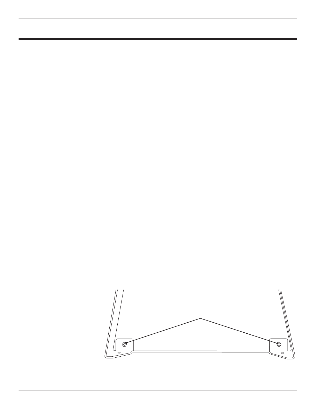
2.2.2 Support Leg Gusset
The bottom of each support leg is constructed with an integrated gusset design. In each
corner, the Installer will be required to secure the gusset using a 1 in. Button Head Hex Screw,
washers and nut. Place a washer on the 1 in. Button Head Cap Screw and insert into the hole
in the Support Leg and gusset. Place a washer on the inside and thread a nut onto the Button
Head Cap Screw. Use
socket and ratchet
to tighten the nut,
securing the gusset.
1 in. Button Head
Cap Screw

15Bend-Tech Dragon A400
Cooling System Assembly
02
Cooling System Assembly Manual
2.2.3 Leveling Feet
Locate the Leveling Feet in the hardware bag. Thread a nut onto each leveling foot, leaving
about an inch between the base of the foot and the nut. Insert a Leveling Foot into the hole at
the bottom of each Aluminum Support Leg.
Thread a second nut
onto the Leveling
Foot after inserting it
in the mounting hole
on the bottom of the
Aluminum Support
Leg. Do not tighten.
Leave space for
adjustment of the
Aluminum Support
Leg.
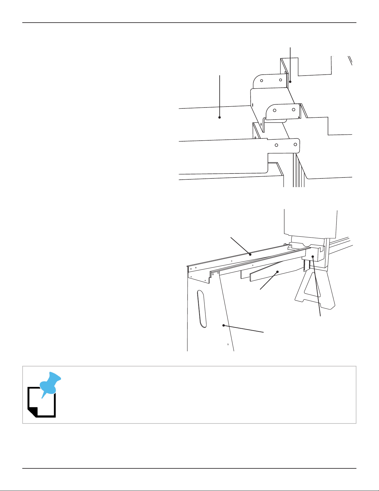
2.2.4 Parts Catcher
Place the Parts Catcher on the Beak at
the Head of the machine, just in front
of and under the Gate opening.
Locate eight ¾ in. button head screws,
nuts and washers from the hardware
bag. Insert the eight fasteners through
the slotted opening in the Parts
Catcher, aligning them with the holes in
the Beak.
Ensure the screw heads are on the
outside of the assembly and the nuts
and washers are on the inside. Thread
the nuts on and snug them down. Do
not tighten the nuts at this time.
2.2.5 Attach Water Tray to Parts
Bend-Tech recommends enlisting a helper when assembling the Water Tray System.
Head of Machine
Parts Catcher
4 Bolts
per side
Leveling Feet
16 Bend-Tech Dragon A400
Cooling System Assembly
02
Cooling System Assembly Manual
Catcher
When assembling the Water Tray
System, the face of the Water Tray
Tray will connect to the Parts Catcher
Water Tray behind the lip of the Parts
Catcher.
Use one of the Aluminum Support Legs
to support the free end of the Water
Tray. Use four ¾ in. button head screws,
nuts and washers to attach the side tabs
on the Water Tray to the Parts Catcher.
Feed the screws through the side of the
Water Tray so the head of the screw is
inside the Water Tray and the nut and
washer are on the outside.
Use a punch or small Phillips head screwdriver to help align the mounting holes in the
Water Tray system.
Head of Machine
Tray 1
Support Leg
Beak
Parts Catcher
Parts Catcher
Tray 1
17Bend-Tech Dragon A400
Cooling System Assembly
02
Cooling System Assembly Manual
Locate one of the rollers from the parts
bag. Using two 1 in. button head screws,
nuts and washers, attach the roller on
the inside face of the Water Tray where it
connects to the Parts Catcher. Feed the
button head screw through the roller and
through the mounting holes in the Water
Tray and the Parts Catcher. Ensure the
roller is placed as far up as possible.
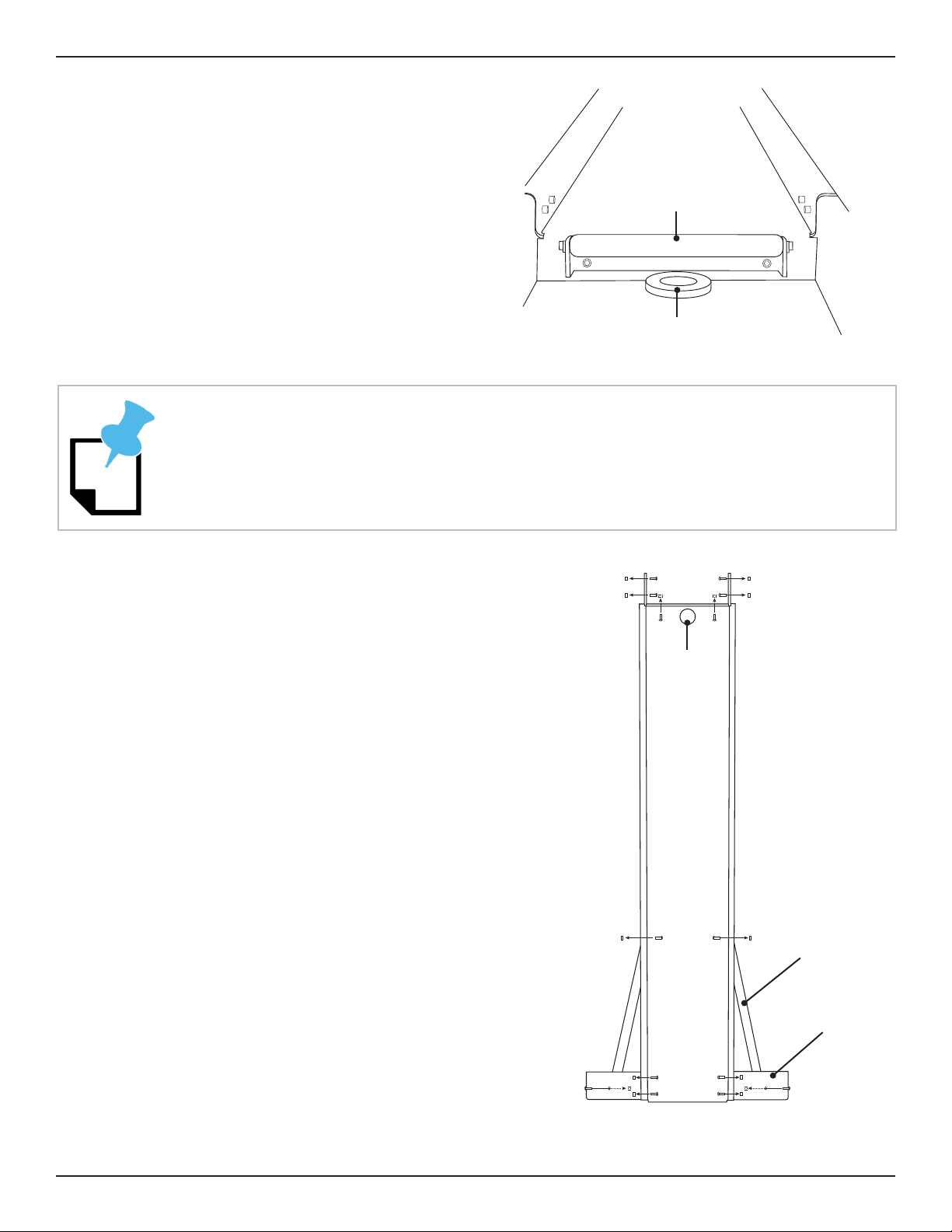
2.2.6 Water Tray System Assembly
Position the second Water Tray behind the
Aluminum Support Leg to support the free
end of the second Water Tray. Position
mounting surface is on the outside of both
water trays. Align the four mounting holes
in the Aluminum Support Leg with the
and the side tabs on the second Water
Tray.
Fasten the sides of the Water Trays and
Aluminum Support Leg together using
four 1 in. button head screws, nuts and
washers. Ensure the heads of the screws
are on the inside of the water tray and the
nuts and washers are on the outside. Do
not tighten.
Top View
Drain
Support Leg Brace
Support Leg
Tray or Parts
Catcher
Drain
Roller
Do not tighten any fasteners on the Tray System Assembly until all components of the
Tray System Assembly are connected.
18 Bend-Tech Dragon A400
Cooling System Assembly
02
Cooling System Assembly Manual
Repeat this process with the third Water Tray.
2.2.7 C Bracket
Place the C Bracket at the front end of
Aluminum Tray No. 3. Align the mounting
holes of the third Aluminum Support Leg
with the holes in the Water Tray and C
Bracket.
with the heads on the inside of the Water
Tray and the nuts and washers on the
outside of the Aluminum Support Leg.
Below the C Bracket, insert two ¾ in.
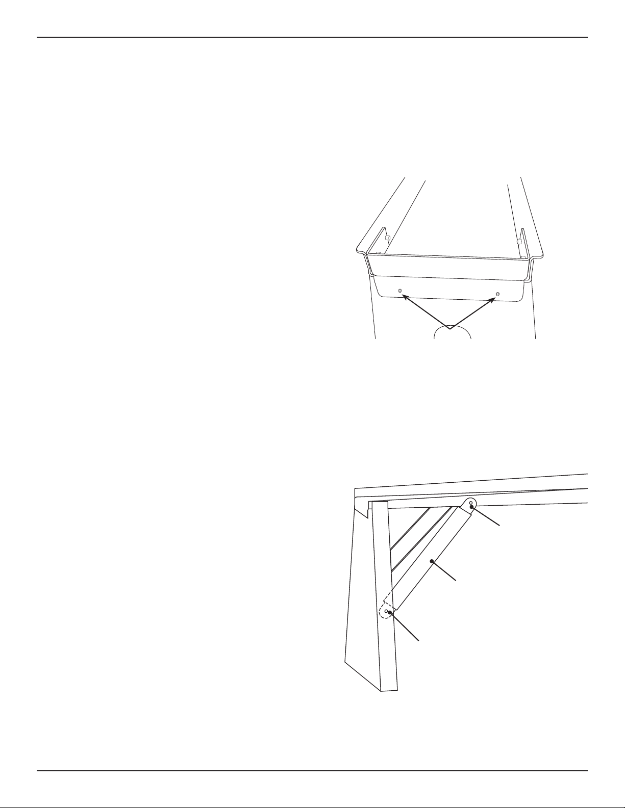
2.2.8 Aluminum Support Leg Braces
Starting at the front of the system, use (12)
¾ in. button head screws, washers and nuts
to attach the Aluminum Support Leg Braces
to the Aluminum Support Legs and the
Water Trays.
Support Leg Brace to the inside the of the
Aluminum Support Leg, inserting the button
head screws so the head is on the outside
of the Aluminum Support Leg and nut and
washer are on the inside.
Attach the bent end of the Aluminum
Support Leg Brace to the outside of the
Water Tray, feeding the button head screw
from the inside of the Water Tray and the
nut and washer are on the outside.
Outside of Tray
(Bent End)
Support Leg Brace
Inside of Support
Leg (Flat End)
Tray 3
C-Bracket
fasteners

19Bend-Tech Dragon A400
Cooling System Assembly
02
Cooling System Assembly Manual
2.2.9 Finishing the Tray System Assembly
Braces. Tighten securely. Take care to position the rollers so they sit above the surface of the
Tray System, adjusted as high as possible.
2.3 Water Tray Drain System
The Cooling System’s Water Tray Drain
System collects water from the Tray
System, holds it in the Cooling System
Reservoir and recirculates it back through
the material.
2.3.1 Bung Installation
Locate the four drain bungs in the PVC
parts bag. Remove the coupling nuts from
each drain bung. Insert a bung into the
drain hole in each Aluminum Tray and in
the Parts Catcher. Thread the nuts back
onto each bung underneath the Aluminum Tray and tighten securely using a large channel lock
pliers. Locate the male/female couplers in the PVC parts bag. Thread one PVC male/female
coupler into each drain bung.
Also thread one PVC coupler into the bung inside the parts catcher. This will allow the Parts
Catcher to hold water to help cool parts.
Teon tape or plumber’s tape can help seal the male/female coupler in the drain bung.
Drain Bung
Male/Female
Coupler
When in use, the rollers should keep parts from resting on the bottom of the Tray
System.
20 Bend-Tech Dragon A400
Cooling System Assembly
02
Cooling System Assembly Manual
2.3.2 PVC Drain Installation
The PVC drain system is installed beginning at the Parts Catcher and then working to the end
of the Tray System. The PVC Parts are numbered in order of installation. During this process
the Installer will also place and connect the Cooling System Reservoir. Using PVC cement,
install the parts per diagram 2.3.3.
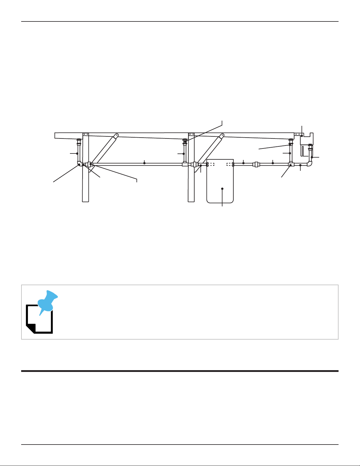
2.3.3 Tray System Drain Diagram
2.3.4 Placing the Cooling System Reservoir
Place the Cooling System Reservoir according the diagram in section 2.3.3. Install the screens
on the drains feeding into the Cooling System Reservoir. Secure using zip ties.
Fit the No. 5 and No. 6 PVC pieces through the grommets in the reservoir.
2.4 Water Pump
The Cooling System requires the addition of a water pump to be operational. Because
customer needs can vary, Bend-Tech does not supply a water pump with the Cooling System.
The Customer will be required to supply a water pump to complete the Cooling System. Refer
Drain Bung
Coupler
Parts Catcher
Union Fitting
Elbow Fitting T Fitting
Cooling System
Reservoir
1
2
3
45
8
9
10
11
6
Depending on the size of the the water pump used, the pump may need to be placed
into the reservoir prior to connecting the reservoir to the rest of the PVC drain system.
Other manuals for Dragon A400
14
Table of contents
Popular Accessories manuals by other brands


Visonic
Visonic DUO 200 installation instructions

Rice Lake
Rice Lake IQ plus 310A Technical and service manual

ISYGLT
ISYGLT LS-05-HF-WH Technical Data/Instruction Manual

Garmin
Garmin TruSwing Quick start manual

Gin Gliders
Gin Gliders Safari Pilot 2 user manual

Omega Engineering
Omega Engineering Series Micro Flow Sensor FP-5060 user guide


