Bend-Tech Dragon A400 User manual
Part 1 of 1
Assembly Manual
Revision 08 | English ©2022 Bend-Tech LLC
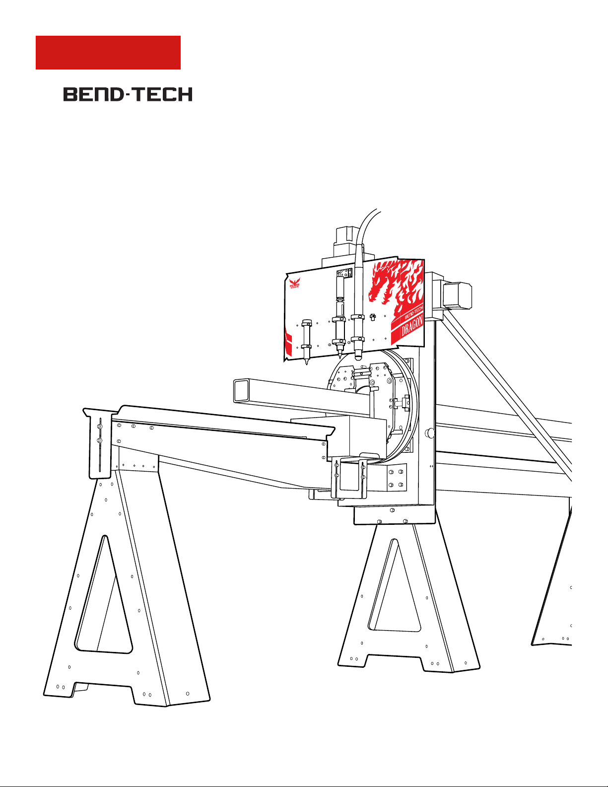
Dragon A400

ii Bend-Tech Dragon A400
Assembly Manual
©2022 Bend-Tech LLC
All rights reserved. The information in this manual is subject to change without notice.
Bend-Tech LLC strives to produce the most complete and accurate information regarding
its products. We are constantly working to improve and advance our products to increase
performance, user satisfaction and experience. Bend-Tech LLC assumes no responsibility for
errors or omissions regarding this manual. Bend-Tech LLC assumes no liability for damages
resulting from the use of the information contained in this publication.

iiiBend-Tech Dragon A400 Assembly Manual
Dragon A400
Assembly Manual
Revision 08
English
Original Instructions
October 2022
Bend-Tech LLC
729 Prospect Ave.
Osceola, WI 54020 USA
(651) 257-8715
www.bend-tech.com

iv Bend-Tech Dragon A400
Assembly Manual
Contents
Contents
Contents..........................iv
Limited Warranty ...................vi
Customer Satisfaction Commitment. . . . .vii
Customer Service. . . . . . . . . . . . . . . . . . .vii
Alerts ........................... viii
Glossary..........................x
01
Safety....................................... 12
1.1 Introduction ................... 12
1.2 Assembly Safety. . . . . . . . . . . . . . . . 12
1.2.1 Safety Equipment .......... 13
02
Tools and Equipment ............. 14
2.1 Tools......................... 14
2.1.1 Tool List .................. 14
2.2 Crate Parts List ................ 15
2.3 Optional Parts ................. 15
2.4 Electrical Requirements .......... 16
03
Assembling the Dragon ......... 17
3.1 Shipping Crate ................. 17
3.1.1 Dragon A400 Shop Position. . . 17
3.1.2 Crate Disassembly. . . . . . . . . . 17
3.3 Getting Started................. 18
3.3.1 Component Boxes .......... 19
3.3.2 Miscellaneous Box.......... 19
3.4 Unpacking the Crate ............ 19
3.5 Moving the head into Position ..... 20
3.6 Installing the Beams............. 22
3.6.1 Install the First Beam........ 22
3.6.2 Slide Support Leg #4 into
Position....................... 23
3.6.3 Position the First Rack....... 23
3.6.4 Install the Second Beam ..... 23
3.6.5 Set the Second and Third Rack 24
3.6.6 Fasten the Support Legs to the
Beams. . . . . . . . . . . . . . . . . . . . . . . . 24
3.6.7 Place and Install the Tail ..... 25
....... 25
3.8 Secure the Support Beam ........ 25
3.8.1 Secure the Support Legs..... 25
3.8.2 Secure the Rails ........... 26
3.9 Set the Rack Spacing. . . . . . . . . . . . 26
3.10 Install the Cable Track Tray ...... 27
3.11 Install the Parts Catcher ......... 28
04
Leveling and Alignment ......... 30
4.1 Leveling and Alignment Overview .. 30
4.1.1 Checking Support Beam Level 30
4.1.2 Adjusting Swivel Levelers .... 30
4.2 Straightening the Dragon A400 .... 31

vBend-Tech Dragon A400 Assembly Manual
Contents
4.2.1 Checking the Straightness.... 31
4.2.2 Rail Splices ............... 32
05
Mounting to the Floor............. 33
5.1 Mounting Overview ............. 33
5.2 Concrete Sleeve Anchors. . . . . . . . . 33
5.3 Preparing the Floor Brackets ...... 34
5.4 Install Concrete Sleeve Anchors ... 34
06
Cables and Control Box......... 35
6.1 Preparing Cable Track ........... 35
6.2 Installing the Cable Track......... 36
6.4 Install the Control Box ........... 37
6.5 Control Box Connections ......... 38
07
Air Line .................................... 39
7.1 Air Line Connection Overview ..... 39
08
Torch........................................ 40
8.1 Torch Cable ................... 40
8.1.1 Torch Ground .............. 40
8.2 Install the Torch Wand ........... 41
8.3 Route the Torch Lead............ 42

vi Bend-Tech Dragon A400
Assembly Manual
Limited Warranty
Limited Warranty
Covering Bend-Tech Dragon
Bend-Tech LLC provides a limited warranty on all new Dragon machines that are manufactured
directly or under license by Bend-Tech LLC, and sold by Bend-Tech LLC or its approved
distributors.
Warranty Coverage
Each Bend-Tech Dragon machine is warrantied by the manufacturer against defects in material
workmanship for 12-months. The warranty period commences upon delivery of the Dragon
machine to the customer’s facility.
Repair or Replacement Only
The Manufacturer’s sole liability, and the Customer’s exclusive remedy under this warranty
shall be limited to repairing or replacing the defective part. Repair or replacement of parts
is at the sole discretion of the manufacturer. The Customer is responsible for warranty parts
installation. Bend-Tech does not provide warranty service labor.
Limits
This warranty does not cover components subject to wear due to normal use of the machine
such as belts, lights, tooling etc. This warranty is void if Bend-Tech LLC has determined any
failure is the result of mishandling, abuse, misuse, improper installation, improper storage,
become void or limited in the event that hardware changes or adaptations are made to the
machine.
Software
The standard 2-year software maintenance plan is included with the purchase of a Dragon.
Before the 2-year maintenance plan has expired, the customer may purchase an extended
maintenance plan. The maintenance plan and extended maintenance plans will ensure the
customer always has the newest version of Dragon Software. The maintenance plan is critical
to keeping Dragon software updated with the newest capabilities possible, and is critical to the
servicing of the machine. Bend-Tech LLC will contact the Customer regarding updates to the
maintenance plan within 1-month of expiration. Contact Bend-Tech Support to ensure software

viiBend-Tech Dragon A400 Assembly Manual
Customer Service
Customer Satisfaction Commitment
Congratulations on your purchase of the world’s best CNC plasma tube and pipe cutting
machine, the Bend-Tech Dragon. Bend-Tech LLC places great pride in customer satisfaction
our support is a key factor in your success.
Contact Us
Bend-Tech’s hours of operation are Monday - Friday, 8:00 am - 5:00 pm EST. The Bend-Tech
support team and sales team are always available during our hours of operation.
Phone: 651-257-8715
Email: Sales team: [email protected]
Address: Bend-Tech, 729 Prospect Ave., Osceola, WI 54020, U.S.A..
Customer Service
Comments, questions, or concerns regarding the Dragon Machine, this manual, or the Bend-
Tech Software can be directed to Bend-Tech sales and service representatives at the above
contact information. Check out the following links for more information regarding Dragon
Machines and Bend-Tech Software.
Website, Socials, and Online Resources
• http://www.bend-tech.com
• https://www.facebook.com/2020ssi
• https://www.instagram.com/bend_tech
• https://www.youtube.com/bendtech2020
• http://www.bend-tech.com/wiki7
viii Bend-Tech Dragon A400
Assembly Manual
Alerts
Alerts
Denitions & Examples
Danger
! Danger !
Danger indicates a serious condition that could cause severe injury or death to the
operator or bystanders if the instructions are not followed.
Warning
! Warning !
A Warning indicates there is a possibility for minor injury if the instructions are not
followed correctly.
Caution
! Caution !
Caution warns the operator that minor injury or machine damage could occur if
instructions are not followed. It could also mean that not following directions could

ixBend-Tech Dragon A400 Assembly Manual
Alerts
Important Alerts
Important
unique to an operation.
Notes and Tips
Note or Tip
Notes and tips give additional helpful information for operating the Dragon machine or Dragon
software. They are meant for supplemental information and not information that is critical for
operating procedures.

xBend-Tech Dragon A400
Assembly Manual
Glossary
Glossary
Axis
Beak
The front assembly that includes the
Parts Catcher and Parts Bin/Bucket.
The Material Coolant System replaces
most of the Beak when installed.
CAD
Computer Aided Design. Modeling or design
software for creating parts, components, or
whole assemblies. Used for manufacturing or
similar industries. Can be 2D or 3D design.
CAM
Computer Aided Manufacturing or Machining.
Using the computer to assist in operating
machines by converting CAD models into
G-Code that the machine recognizes.
Chuck
Secures and rotates the material. Part of
the Trolley. Also referred to as the Y-Axis.
Control Box
Contains the motor drivers and other electrical
components that allows the Dragon CAM
software to control the Dragon machines.
Deadzone
The space between the Chuck and
the Laser Light position when the
Chuck is all the way forward.
Emergency Stop
Abbreviated E-STOP. A button which shuts down
machine operations. Four are located on the
machine and one is part of Machine Control.
Gate
The adjustable mechanism that holds the
material in place at the Head of the Machine.
Head
The machine assembly that makes
up the front end of the machine.
Limit Switch
The switch that operates as an automatic
control to prevent a mechanism or process
from going beyond a prescribed limit.
Load Position
The position the machine enters after
time after starting a cutting project. This
allows the operator to more easily load the
designated material into the machine.
Mach3
The driving software behind Machine Control.
Required for the machine to operate.
Machine Control
The computer interface that controls
the machine operations. Used by the
operator when running projects.
Material Coolant System
The system that transports coolant through
the material during cutting operations.
Material Support Lift
The mechanism that supports the
material during cutting. Sometimes
referred to as the Lifter.
Parts Catcher
The Parts Catcher is placed at the front of
the machine to catch parts as they are cut.
Support Beam
Forms the backbone of the machine. Comprised
of Aluminum Beams and Steel Rails.
Tail
The machine assembly that makes
up the far end of the machine.

xiBend-Tech Dragon A400 Assembly Manual
Glossary
Task Menu
the Dragon Software or the Bend-Tech
software. From this menu various tasks
can be started, such as part designing,
importing, library access, etc.
Toolhead
The machine component that the tools
are attached too. Maneuvers the tools
into position with the A and Z axes.
Trolley
The machine component that
includes the Chuck. Travels along the
Support Beam on the X-Axis.
Beak
Control Box
Toolhead
Chuck
Material
Support Lift
Support Beam
Tail
Trolley
Gate
Head
Dragon A400
Dragon A250

12 Bend-Tech Dragon A400
Assembly Manual
Safety
01
01
Safety
1.1 Introduction
Before assembling the Dragon A400, read this manual and ensure that all personnel involved
in assembling the machine are properly trained in lifting procedures and tool operation. Ensure
all personnel are aware of the dangers and hazards involved in assembling the machine.
Important
Assembling the Dragon A400 requires a moderate level of mechanical skill and
experience. Assembly should not be undertaken by personnel without experience
in assembling machinery or experience in industrial or machine maintenance.
1.2 Assembly Safety
! Danger !
Certain Dragon A400 parts are heavy. Handling them incorrectly could result in
severe injury or possibly death. Always use caution and follow safety procedures for
moving heavy equipment when assembling the Dragon A400.

13Bend-Tech Dragon A400 Assembly Manual
Safety
01
1.2.1 Safety Equipment
Bend-Tech recommends using the proper safety equipment when installing the Dragon A400.
Safety equipment standards for each shop should be outlined in Occupational Safety and
Health Administration (OSHA) standards. Also, individual shops may have their own standards.
Always consult safety regulations before beginning work. Basic safety equipment may include:
! Warning !
Altering the installation methods and procedures outlined in this manual could result
in improper installation, machine damage or personal injury.
Safety Precautions
•
• Have the correct tools listed in the Tool List on hand.
• Enlist help of 1-3 additional personnel trained to install industrial machinery.
• Follow the methods and procedures outlined in this manual.
• Do not attempt to lift heavy materials without assistance.
• Before beginning, ensure the workspace is clean and of appropriate size for
Dragon A400 assembly.
Safety Glasses
Safety Shoes
Work Gloves
Hearing Protection

14 Bend-Tech Dragon A400
Assembly Manual
Tools and Equipment
02
02
Tools and Equipment
2.1 Tools
The Installer(s) should ensure the proper complement of tools are on hand to assemble the
Dragon A400. Bend-Tech does not recommend attempting to assemble the machine without
the tools listed in this chapter.
2.1.1 Tool List
The following are the recommended tools needed to perform the complete assembly
procedure.
• Forklift
• Cordless drill/driver
• T25 bit
• Support Blocks
• Side cutters
• Tin snips
•
•
•
•
•
• Level (laser, digital or bubble)
• Ratchet
•
•
•
•
•
• Rubber mallet or Dead Blow plastic
hammer
• Tape measure
• Zip ties
• Clamp
• Magnet Tool (Provided)
• Bridge Rack (Provided)

15Bend-Tech Dragon A400 Assembly Manual
Tools and Equipment
02
2.2 Crate Parts List
2.3 Optional Parts
Dragon A400 Assembly
• Machine Head
• Machine Tail
• Support Beam Section (2)
• Rail Support Leg (2)
• Rack (3)
• Beak
• Cable Track Front Support (2)
• Cable Track Beam Mount (1)
• Cable Track Rear Support (10)
• Trolley Housing
• Chuck
• Computer
• Monitor
Miscellaneous Box
• Startup Manual (1)
•
• Swivel Levelers (14)
• Wrench (1)
• Magnetic Tool (1)
• ¼ T-Handle Allen Wrench (1)
• Ethernet Cable (1)
• Power Cable (1)
• Torch Cable (1)
• Coiled Wire Harness Tubing (1)
• Hardware Bags (5)
• String (1)
• Bridge Rack (1)
Technology Package
• Computer Cabinet
• Battery Backup
•
•
• Feeler Gauge Set (1)
• Vernier Caliper (1)
• Torpedo Level (1)
• 26 Piece Radius Gauge Set (1)
• WD40 Gel Lube (1)
• Main Drive Belt 260 XL (1)
• Thomson Sensor (1)
Plasma Unit

16 Bend-Tech Dragon A400
Assembly Manual
Tools and Equipment
04
2.4 Electrical Requirements
• 220-240v Outlet (for plasma system - see owner’s manual for more information)
• 1x - 110-120v 20Amp Outlet (A250 & A400 machine)
• Misc 110-120v Outlets (computer, monitor, etc.)

17Bend-Tech Dragon A400 Assembly Manual
Assembling the Dragon
03
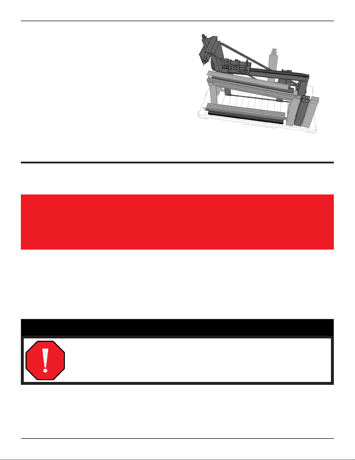
3.1 Shipping Crate
The Dragon A400 is shipped from the Bend-Tech manufacturing facility in a custom-fabricated
the protection of the Dragon A400 during shipping. The Dragon A400 machine is completely
secured within the crate for shipping purposes. Components may be bolted to the crate, shrink
wrapped, and secured with plastic or metal banding. The order in which components are
removed from the crate is important in executing proper assembly of the machine. For best
results in assembling the Dragon A400, carefully follow the steps outlined in this Assembly
Manual.
3.1.1 Dragon A400 Shop Position
Before beginning assembly, ensure there is adequate space to accommodate the machine on
will be needed if the material cooling system is installed.
3.1.2 Crate Disassembly
03
Assembling the Dragon
! Caution !
Enlist the help of additional personnel when removing components from the crate
and assembling the machine. A dropped crate component could cause injury to
bystanders or damage the machine. Crate sides are large and heavy and should
not be lifted without help.

18 Bend-Tech Dragon A400
Assembly Manual
Assembling the Dragon
03
REQUIRED TOOLS & EQUIPMENT
• Drill
• T25 Bit
the larger crate sides, including the fasteners that secure the 2x4 braces, and set it aside.
! Caution !
When removing the 2x4 braces, ensure someone is holding them to prevent the
2x4s from falling onto the machine or other personnel.
Unfasten and remove the 2x4 braces at the top of the crate. Next, unfasten and remove the
crate ends. Set these aside. Remove the remaining large crate side last, and set it aside.
3.3 Getting Started
REQUIRED TOOLS & EQUIPMENT
•
• Tin Snips
•
• Forklift
• Support Blocks
Removing the Dragon A400 components from the crate properly, and keeping them in order,
is critical to achieving the quickest, most seamless installation possible. As shipped, the
components of the machine will be secured to the each other and the crate.

19Bend-Tech Dragon A400 Assembly Manual
Assembling the Dragon
03
Important
Do not remove any strapping or shrink wrap from the head of the Dragon A400.
It is important to keep components secure while the head is being removed from
the crate.
3.3.1 Component Boxes
Remove the various component boxes packed around the Dragon A400 machine. The
Component Boxes are labeled for reference during the assembly process.
3.3.2 Miscellaneous Box
Locate the Miscellaneous Box, and remove the 14 Swivel Levelers. These need to be installed
on each Support Leg during assembly.
Important
crate using the Floor Brackets. When assembling the machine, the Floor
Brackets should be left in place. The Installer will use the Swivel Levelers to true
3.4 Unpacking the Crate
REQUIRED TOOLS & EQUIPMENT
• ½ in. socket and ratchet
• Tin Snips
•
• Forklift
• Support Blocks
Take care to keep components of the machine organized when unpacking the crate, so they
can be located easily. Remove all of the boxes and machine components from the crate except
for the head of the machine. This will need to be removed last using a forklift.
20 Bend-Tech Dragon A400
Assembly Manual
Assembling the Dragon
03
Use a ½ in. socket and drill to remove the
major components of the machine. Tin
snips will be required to remove the Support
Beams. The middle three racks are secured
remove the racks. Only loosen the racks
enough to slide them out. Take care not to
damage the racks when moving them.
3.5 Moving the head into Position
The head of the machine is extremely heavy. Great care should be taken not to damage any
machine’s components during moving and installation.
Important
Remove all other contents of the crate before attempting to move the Head of the
machine.
Use a ½ in. socket and drill to remove the lag bolts securing the head of the machine to the
Approach the head of the machine from the front with the forklift. Position the forks under the
head in the indicated position. It is recommended the installer use fork extensions and lay
blocks of wood across the forks to support the beam of the machine.
! Danger !
The head of the machine is heavy. Bend-Tech does not recommend placing the
head of the machine manually. If the head falls or tips over it could cause severe
injury or death.
Other manuals for Dragon A400
14
Table of contents
Other Bend-Tech Welding System manuals


