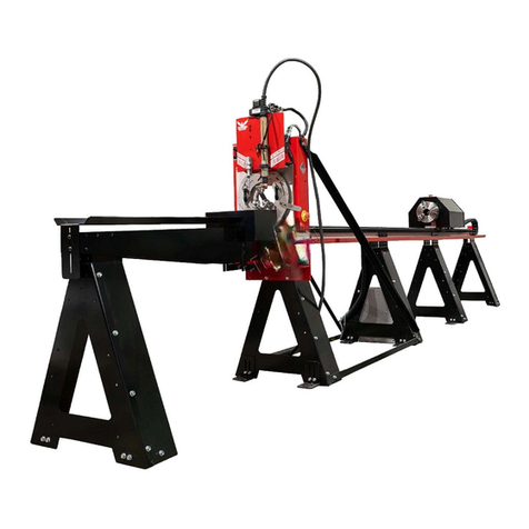
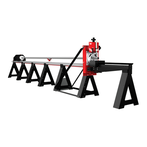
Bend-Tech Dragon A400 Installation guide

Revision 6 | English
A400
Part 2 of 3
Startup and Training Manual
Part 2: Machine Overview, Inspection, and Startup
©2021 Bend-Tech LLC

ii Bend-Tech Dragon A400
Startup and Training Manual
©2021 Bend-Tech LLC
All rights reserved. The information in this manual is subject to change without notice.
Bend-Tech LLC strives to produce the most complete and accurate information regarding
its products. We are constantly working to improve and advance our products to increase
performance, user satisfaction and experience. Bend-Tech LLC assumes no responsibility for
errors or omissions regarding this manual. Bend-Tech LLC assumes no liability for damages
resulting from the use of the information contained in this publication.

iiiBend-Tech Dragon A400 Startup and Training Manual
Dragon A400
Start-Up and Training Manual
Revision 6
English
Original Instructions
Janurary 2021
Bend-Tech LLC
729 Prospect Ave.
Osceola, WI 54020 USA
(651) 257-8715
www.bend-tech.com

iv Bend-Tech Dragon A400
Startup and Training Manual
Contents
Contents
Contents...................................iv
01
Machine Overview ................... 7
1.1 Introduction ....................7
1.2 Gate Overview ..................7
1.2.1 Gate Eccentric Bearing .......8
1.2.2 Gate Lead Screws ...........9
1.2.3 Gate Adjustment ............9
1.2.4 Gate Clamp ................9
1.3 Material Support Lift Overview......9
1.3.1 Material Support Lift Operation 10
1.3.2 Air Cylinder Adjustment ...... 10
1.4 Toolhead.......................11
1.4.1 Toolhead Actuators ..........11
1.4.2 Marker Holder ............. 12
1.4.3 Engraver ................. 12
1.4.4 Engraver Air Regulators. . . . . . 12
1.4.5 Torch .................... 13
1.4.6 Laser Light................ 13
1.5 Electrical Components Overview ... 13
1.5.1 Emergency Stops (E-Stops) .. 13
1.5.2 E-Stop Wiring. . . . . . . . . . . . . . 13
1.5.3 Homing Sensors ........... 14
1.5.4 Homing Sensor Designations
and Locations .................. 14
1.6 Motor Cable Connections Overview 15
1.7 Hypertherm Unit................ 15
1.7.1 Hypertherm Overview ....... 15
1.7.2 Hypertherm Cable .......... 15
1.7.3 Ground Connection ......... 15
1.7.4 Amperage ................ 16
1.7.5 Air Supply. . . . . . . . . . . . . . . . . 16
1.7.6 Gas ..................... 17
1.7.7 Consumables.............. 17
1.7.8 Consumables Part List. . . . . . . 17
02
Machine Inspection ................ 19
2.1 Machine Inspection ............. 19
2.2 Rail Inspection ................. 20
2.2.1 Check Rail Assembly........ 20
2.2.2 Check Rail Level ........... 21
2.2.3 Check Rail Straightness ..... 22
2.3 Electrical Inspection ............. 23
2.3.1 Motor Cables .............. 24
2.3.2 Motor Cable Locations....... 25
2.3.3 Axis Sensor Cables ......... 25
2.3.4 Emergency Stop Cables ..... 26
2.3.5 Ethernet Port .............. 26
2.3.6 Laser Light Cord ........... 27
2.3.7 Tool Connections ........... 27
2.3.8 Ground Cable ............. 27
2.3.9 Check the Breakout Board. . . . 28

vBend-Tech Dragon A400 Startup and Training Manual
Contents
2.3.10 Connect Power ........... 28
2.3.11 Check for 5 Volts .......... 29
2.3.12 Check E-Stops............ 29
2.4 Air Line Connection ............. 30
03
Machine Control Startup........ 31
3.1 Machine Control Startup ......... 31
3.2 Booting Up The Dragon A400 ..... 31
3.2.1 Power On Computer ........ 31
3.3 Power On Control Box ........... 32
3.3.1 Main Power Switch ......... 32
3.3.2 Green Power Button ........ 32
3.3.3 Launch Bend-Tech 7x ....... 32
3.3.4 Dragon A400 Software Color
Designations................... 32
3.3.5 Bend-Tech Launcher ........ 33
3.3.6 Machine Control. . . . . . . . . . . . 33
3.3.7 Mach3 Machine Control ..... 34
3.3.8 Enable Machine............ 34
3.4 Jog Controls System Check....... 34
3.4.1 Open Jog Controls.......... 34
3.4.2 Motor Location and Operation
Index......................... 35
3.4.3 Jogging the Machine ........ 35
3.5 Homing The Machine............ 36
3.5.1 Homing an AXIS ........... 36
......... 36
3.5.3 Jog the Trolley ............. 37
3.5.4 Home All Axis.............. 37
3.6 Hypertherm ................... 38
3.6.1 Hypertherm Power Switch .... 38
3.6.2 Hypertherm Cut Type........ 39
3.6.3 Hypertherm Air Supply....... 39
3.6.4 Hypertherm PSI Settings ..... 39
3.6.5 Hypertherm Cut Settings ..... 39

vi Bend-Tech Dragon A400
Startup and Training Manual
Contents

7Bend-Tech Dragon A400 Startup and Training Manual
Machine Overview
01
01
Machine Overview
1.1 Introduction
This chapter overviews general information on the Bend-Tech Dragon A400. This general
information is a starting point to learn about the Dragon A400. For detailed information on
operation and troubleshooting, please refer to your Bend-Tech Dragon A400 Operator’s
Manual.
1.2 Gate Overview
The gate is located at the front of the Dragon A400. The gate works in conjunction with the
chuck to support and move the material through the cutting process. There are two styles of
gate that the Dragon A400 can come equipped with: a non-powered gate and a powered gate.
Gate Type Function
Non-Powered Gate Round, square or rectangle material. Does not support
angle or channel
Powered Gate Round, square, rectangle, angle or channel material.
Essential when processing angle or channel.

8Bend-Tech Dragon A400
Startup and Training Manual
Machine Overview
01
1.2.1 Gate Eccentric Bearing
The gate rides upon three bearings located on the
back face of the gate assembly. The gate should ride
smoothly on its bearings with no binding. If there is
play in the gate or if the gate binds while moving,
the gate eccentric bearing may need adjustment.
Please, contact customer support before adjusting the
eccentric bearing.
A Dragon A400 machine equipped with
a Non-Powered Gate will not have a
C-Axis drive motor or ring gear.
A Dragon A400 machine equipped
with a Powered Gate will include
the C-Axis drive motor and
Powered Gate Ring Gear.
Front Gate Rollers
Front Lead Screw
Rear Lead Screw
C Axis Drive motor
and gear
Powered Gate Ring Gear
Non-Powered Gate Powered Gate
Front Gate Eccentric
Bearing
Important
Keeping the gate clean is key to maintaining optimum performance of the Dragon.
Refer to maintenance guidelines for the gate for cleaning procedures and intervals.

9Bend-Tech Dragon A400 Startup and Training Manual
Machine Overview
01
1.2.2 Gate Lead Screws
The lead screws are used to adjust the opening of the gate. The gate uses two lead screws,
positioned 90 degrees from each other. Adjust the lead screws using a ¼ in. Allen wrench,
which is provided with the machine. Turning the lead screws clockwise closes the gate, and
turning them counterclockwise opens the gate. The gate lead screws should operate smoothly
with minimal force and no binding throughout the travel.
1.2.3 Gate Adjustment
When loading material, the gate should be adjusted so
that the rollers are snug against the material. The rollers
should not be overtightened, and should spin by hand, but
not spin freely. The material needs to move freely within
When no material is loaded into the gate, the gate rollers
should spin freely without binding or sticking.
1.2.4 Gate Clamp
The gate clamp is used on non-powered gates to
lock the gate into one position. It is used only for
round stock. The gate clamp is critical to keeping
round stock in position during cutting. Always lock
the gate with the lead screws in the 12 o’clock and
3 o’clock positions.
1.3 Material Support Lift Overview
The material support lift is used to support extremely long or thin material. Long material can
support lift can accommodate up to 6-inch OD round stock or 4-inch diameter square stock. By
default the material support lift will activate for material stock over 10 feet (3 meters).
Important
The gate will only need
to be adjusted when
changing material types
or sizes, or for removing
remnant material.
Reminder
Machines equipped with the powered gate
do not come equipped with a gate clamp.
Front Gate
Gate Clamp
E-Stop

10 Bend-Tech Dragon A400
Startup and Training Manual
Machine Overview
01
1.3.1 Material Support Lift Operation
The material support lift is
powered by the B-Axis motor
which moves the lift up and
down. The rotation of the
material support lift is achieved
via a pneumatic cylinder.
The pneumatic controls for
the material support lift are
pre-set to 60 psi. However,
line pressure going into the
of operation of the material
support lift so some adjustment
may be necessary.
1.3.2 Air Cylinder Adjustment
The speed of the material
support lift rotation is controlled
by a needle valve adjustment screw on either
end of the air cylinder. The right side needle
valve adjustment controls the inward rotation
of the material support lift (toward the Rail).
The left side needle valve adjustment controls
the outward rotation of the material support
lift (away from the Rail).
Material Support
Lift in use
Material Support
Lift not in use
Left Needle Valve
Right Needle Valve
Material Support
Lift Air Regulator
Important
When adjusting the
needle valves on the
Material Support Lift air
cylinder it is best to turn
them ¼ turn at a time to
avoid over adjustment
and possible damage
to the assembly.

11Bend-Tech Dragon A400 Startup and Training Manual
Machine Overview
01
1.4 Toolhead
The toolhead on the Dragon A400 serves as the tool mount, and the vehicle for engaging the
tools vertically and horizontally during the machine’s operation. It is located at the front of the
Dragon A400. The marker holder, engraver, torch, and laser light are mounted to the Toolhead.
1.4.1 Toolhead Actuators
The toolhead is controlled
by the A-Axis and Z-Axis
motors. The motors use
actuators to perform vertical
and horizontal movement of
the toolhead. The actuators
should be kept clean and
free of dust and debris. The
actuators are key to smooth,
accurate, and consistent
operation of the toolhead.
Torch
Laser Light
Z Axis Motor
Marker Housing
Engraver
A Axis Motor
A-Axis Motor
Z-Axis Motor
Vertical Actuator
Screw
Horizontal
Actuator Screw

12 Bend-Tech Dragon A400
Startup and Training Manual
Machine Overview
01
1.4.2 Marker Holder
The marker holder is mounted on the left side of the toolhead. The marker holder sits loose in
its mount on the toolhead so it is able to ride over material easily and without damaging the
marker. Depending on the type of marker being used it may be necessary to modify the marker
body or use a piece of tape to keep the marker secure in the holder.
1.4.3 Engraver
The engraver is mounted in the center of the toolhead. When the engraver is engaged, an
air cylinder is pressurized and the tool is pushed down to meet the material. The pressurized
cylinder, along with the bleeder valve, allows the engraver to ride over contours in the material
without damaging the tool.
1.4.4 Engraver Air Regulators
The engraver is driven by pressurized air. It uses two separate regulators located just
behind the toolhead. The left regulator controls the engraver and is pre-set at the Bend-Tech
manufacturing facility to 70 PSI. The right regulator controls the engraver air cylinder and is
pre-set at the Bend-Tech manufacturing facility to 5-10 PSI.
The engraver cylinder and air regulator also use an air bleeder screw. The bleeder screw is
pressure, ensure the bleeder screw is open all the way.
How clean the material is will aect marker life. If a project requires heavy use of the
marker, clean the material before loading it into the machine. Always keep the marker
capped when not in use.
Engraver Air Pressure Settings
Engraver 70 PSI
Engraver Actuator
Cylinder
5-10 PSI
Right Regulator:
Controls the
Engraver
Left Regulator:
Controls the
Engraver Air
Cylinder
Engraver Bleeder Valve

13Bend-Tech Dragon A400 Startup and Training Manual
Machine Overview
01
1.4.5 Torch
Inspection of the torch is covered in Chapter 2 of the Startup and Training Manual Part 3.
1.4.6 Laser Light
The laser light is used to calibrate the Dragon A400 tools in relation to the material. The laser
light is mounted and calibrated at the Bend-Tech manufacturing facility. No adjustment of the
laser light is necessary.
! Warning !
The laser light can damage human retinas. Never look directly into the laser light.
1.5 Electrical Components Overview
The Dragon A400 uses sensors, switches, and cables to connect each Axis of the machine to
the computer, and to allow the machine to be shut down in case of an emergency. Inspecting
these electrical components on initial startup as well as on a regular basis, will ensure the
Dragon operates on a long-term basis.
1.5.1 Emergency Stops (E-Stops)
There are four Emergency Stop (E-Stop) buttons
on the Dragon A400. There is one on either side
of the toolhead, one on the trolley and one at the
tail.
1.5.2 E-Stop Wiring
It is recommended the operator check the wiring
connections on the E-Stop switches to ensure
secure connections. While these are secured
at the Bend-Tech manufacturing facility, it is
possible for these connections to become loose
and result in a false E-Stop.
Orange Side
Black Wire
Red Wire

14 Bend-Tech Dragon A400
Startup and Training Manual
Machine Overview
01
1.5.3 Homing Sensors
powered gate. These should be checked for function on initial startup using a metal tool such
as the blade of a screwdriver. When touched with a metal tool the sensor will either light up or
the sensor light will go out, depending on the location and type of the sensor.
1.5.4 Homing Sensor Designations and Locations
Homing Sensor
Cable Connection
Homing Sensor
Homing
Sensor Location
X Axis The X-Axis Homing Sensor is located at the end of the beam of the
machine. This sensor homes the Trolley on the beam.
Y Axis The Y-Axis Homing Sensor is located at the Left rear of the Trolley, just in
front of the Chuck Drive Gear. This sensor homes the Chuck.
Z Axis The Z-Axis Homing Sensor is located on the right-hand side of the
Toolhead mount. This sensor homes the Toolhead on its horizontal axis.
A Axis
The A-Axis Homing Sensor is located at the top of the Toolhead mount on
the front of the machine. The machine uses to the A-Axis homing sensor
to home the Toolhead on its vertical axis.
B Axis
The B-Axis Homing Sensor is located inside the Material Support Lift
housing under the Material Support Lift collar sleeve. This sensor homes
the Material Support Lift.
C Axis
The Homing Sensor for the C-Axis is located on the C-Axis Motor
mounting bracket on the left side of the front of the machine. This sensor
homes the Gate.

15Bend-Tech Dragon A400 Startup and Training Manual
Machine Overview
01
1.6 Motor Cable Connections Overview
The majority of motor cable connections and axis sensor cable connections are performed at
the Bend-Tech manufacturing facility. The motor cables, axis sensor cables, and E-Stop cables
will need to be connected to the control box.
1.7 Hypertherm Unit
The Dragon A400 uses a Hypertherm plasma unit to cut the material.
1.7.1 Hypertherm Overview
Bend-Tech recommends the Hypertherm Powermax45 XP, Powermax65 or Powermax85
for use with the Dragon A400. The customer can purchase the Dragon A400 supplied with a
Hypertherm unit or it can be purchased separately.
1.7.2 Hypertherm Cable
The Dragon A400 is supplied with a cable that connects the Hypertherm to the machine’s
control box. This allows the Hyperthem to connect directly to the machine with no
1.7.3 Ground Connection
Bend-Tech recommends using a bolt to connect the ground cable on the Dragon A400
machine to the ground cable of the Hypertherm unit. This requires removing the cable from the
alligator clamp on the Hypertherm cable and connecting it to the Dragon A400 cable.
Other plasma machines will work with the Dragon A400. Contact Bend-Tech Support
for more information.
If the Customer purchases the Hypertherm unit as part of the Dragon A400 package,
Bend-Tech will support the unit and contact Hypertherm regarding issues if necessary.

16 Bend-Tech Dragon A400
Startup and Training Manual
Machine Overview
01
1.7.4 Amperage
Hypertherm units are available for use with the Dragon A400 in 45, 65 and 85 amp versions.
The amperage the customer chooses will depend on the thickness of material being cut as well
as the amount of usage the Dragon A400 will see.
1.7.5 Air Supply
The Hypertherm Powermax 45 minimum air supply requirement is 6 cubic feet per minute
(cfm) at 90 psi. When cutting thicker material it is possible that the Hypertherm unit will
Dragon A400 is appropriate to operate the Hypertherm as well as other working aspects of the
machine. If connected to a separate air source the customer should ensure the air source is
appropriate to supply the Hypertherm unit.
Compressor
6 cfm / 90psi x 1.5-2
Air Filter
Air Dryer
Oil Separator
Moisture Traps
Recommended:
Minimum 1 in. Pipe
Air supply should not
drop below minimum
requirement before
regulator: 6cfm / 90psi.
Gauge and Regulator
Plasma Unit
Air Line and Supply Requirements
Pressure 90-135 psi
Air Line
Air Dryer Yes
Air Filter Yes
Oil/Oil Vapor Separator Yes

17Bend-Tech Dragon A400 Startup and Training Manual
Machine Overview
01
1.7.6 Gas
1.7.7 Consumables
It is recommended that the customer have additional consumables on hand when operating
the Dragon A400. Worn consumables can result in wider and less accurate cuts. consumables
are available through Hypertherm website or via a Hypertherm distributor.
1.7.8 Consumables Part List
220817
Shield
220854
Retaining Cap
220941
Nozzle
220842
Electrode
220858
Swirl Ring
! Danger !
process.
45 Amp Consumables 65 Amp Consumables 85 Amp Consumables
Components Standard Fine Cut Components Standard Fine Cut Components Standard Fine Cut
Nozzle 220941 220930 Nozzle 220819 220930 Nozzle 220816 220930
Electrode 220842 220842 Electrode 220842 220842 Electrode 220842 220842
Shield 220817 220948 Shield 220817 220948 Shield 220817 220948
Swirl Ring 220857 220857 Swirl Ring 220857 220857 Swirl Ring 220857 220857
Retaining
Cap 220854 220854 Retaining
Cap 220854 220854 Retaining
Cap 220854 220854

18 Bend-Tech Dragon A400
Startup and Training Manual
Machine Overview
01

19Bend-Tech Dragon A400 Startup and Training Manual
Machine Inspection
02
02
Machine Inspection
2.1 Machine Inspection
After assembling the Dragon A400, it is important to conduct an initial inspection of
Please follow the procedures outlined in this chapter to ensure all components are inspected
thoroughly.
! Caution !
connections while the machine is powered down and disconnected from power
sources.
It is often the case that a aw in the operation of the machine is the result of
improper setup. Inspecting the machine is critical to eliminating variables in the
troubleshooting process.

20 Bend-Tech Dragon A400
Startup and Training Manual
Machine Inspection
02
2.2 Rail Inspection
The rail forms the ‘backbone’ of the machine. It is assembled from rail guides that the trolley
rides upon, and aluminum beams. Ensuring that the rail is assembled correctly and is straight
and level is critical to the overall operation of the machine.
2.2.1 Check Rail Assembly
The rail is assembled in sections. The number of sections will depend on the length of the
machine. There can be up to four rail sections on the Dragon A400.
1. Ensure that all the screws attaching the support legs to the beams are tight, and no screws
are missing.
2. Ensure that each rail splice
connects the rail sections as
seamlessly as possible. Check that
the four screws securing the rail
splices to the beams at each joint
are fastened properly.
3. Ensure that the swivel levelers are installed. These will need to be adjusted if the machine
is not level.
4.
the anchors will need to be loosened if the machine is not level or straight.
There are two screws, one at the head and one at the tail of the machine, that
are partially unscrewed on the side opposite of the cable track. These are used in
checking the straightness of the machine and should not be adjusted.
3 4 5 The four rack joints
are labeled 1 - 4.
Ensure the numbers
on the racks are
aligned as shown.
Rail Sections vs Rack Sections
1 2 3 4
There are three rail joints, labeled 3, 4,
and 5. Ensure the numbers on the beams
are aligned as shown in the diagram.
Rail Splice
Screws
Other manuals for Dragon A400
14
Table of contents
Other Bend-Tech Welding System manuals
Popular Welding System manuals by other brands

Rohr
Rohr MMA Series manual

Strata
Strata ADVANCETIG 320AC/DC operating instructions
EWM
EWM Taurus 551 Basic S FDG/FDW operating instructions
EINHELL
EINHELL BT-FW 100 Original operating instructions
Hobart Welding Products
Hobart Welding Products Beta 230 Mig owner's manual

iWeld
iWeld MIG 251 DIGITAL user manual
