LORCH S-Pulse User manual

Lorch Schweisstechnik GmbH
Im Anwaender 24 - 26
D-71549 Auenwald
Telephone: +49 7191 503-0
Fax: +49 7191 503-199
Website: www.lorch.eu
Email: [email protected]
909.2710.1-06
Service manual
S-Pulse/S-SpeedPulse XT
P-Basic/-Synergic XT

- 2 -
02.20
Publisher LORCH Schweisstechnik GmbH
Im Anwaender 24 - 26
D-71549 Auenwald
Telephone: +49 7191 503-0
Fax: +49 7191 503-199
Website: www.lorch.eu
Email: [email protected]
LORCH Download-Portal https://www.lorch.eu/service/downloads/
Here you can find more technical documentation about your product.
Document number 909.2710.1-06
Issue date 07/29/2020
Copyright © 2020, LORCH Schweisstechnik GmbH
This documentation including all its parts is protected by copyright. Any
use or modification outside the strict limits of the copyright law without
the permission of LORCH Schweisstechnik GmbH is prohibited and liable
to prosecution.
This particularly applies to reproductions, translations, microfilming and
storage and processing in electronic systems.
Technical changes Our machines are in a constant state of development, and the right is
reserved to make technical changes without notice.
909.2710.1-06

- 3 -
02.20
Table of Contents
909.2710.1-06
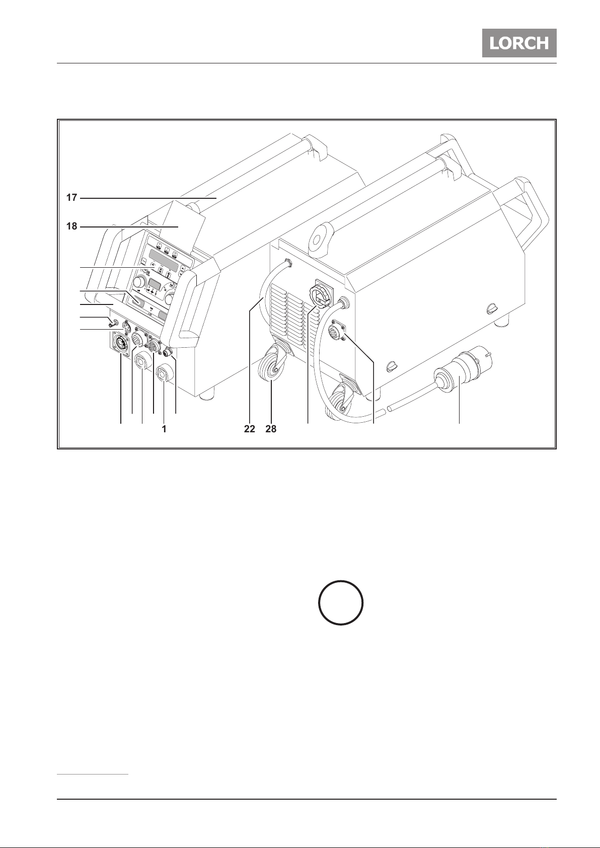
1 Machine elements ................... 4
2 Safety precautions.................. 6
2.1 Requirement ....................................... 6
2.2 Testing Lorch machines according to IEC
60974-4 .............................................. 6
3 Inverter Principle ................... 7
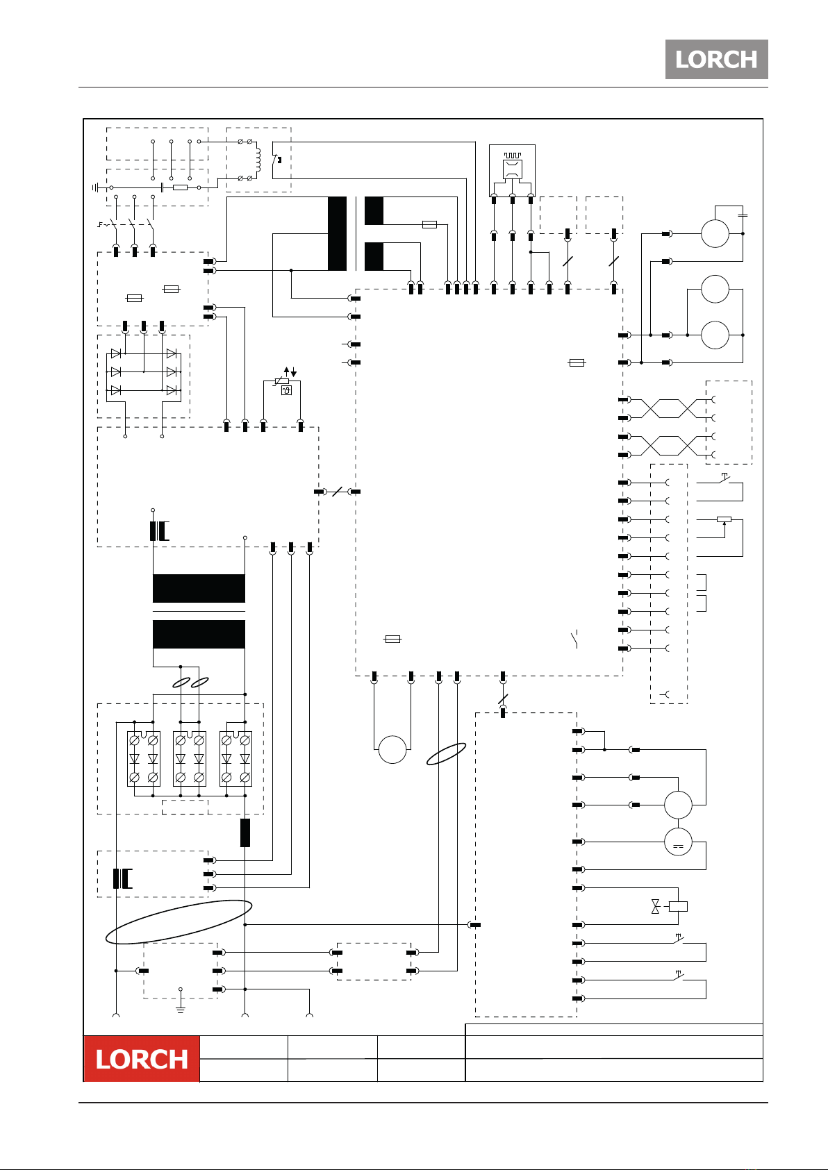
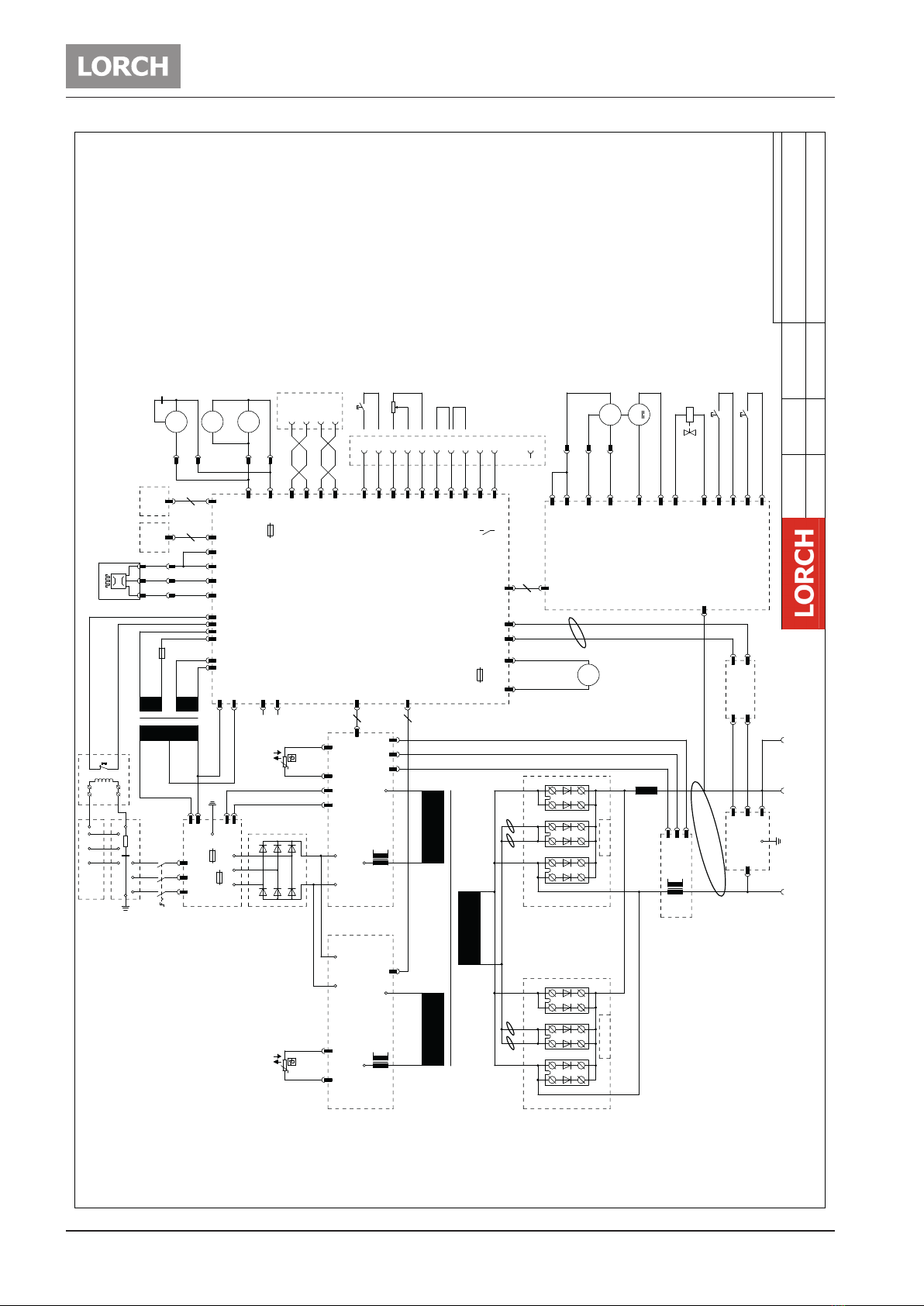
4 Machine Wiring Diagrams ....... 8
5 Common Logic Functions .......12
6 Front panels ..........................12
6.1 Front panel P-Synergic / S-Pulse / S-
SpeedPulse 3.0 ..................................12
6.2 Front panel functions S/P ..................12
6.3 Front panel P-basic ............................14
7 Pc-Boards ..............................15
7.1 Pc-board MAPRO05 ............................15
7.2 Pc-board DMR ....................................20
7.3 Pc-board PP90R .................................22
7.4 Pc-board DMRPP04 ............................23
7.5 Pc-board ZVP .....................................26
7.6 Pc-board DS20BF ...............................28
7.7 Pc-board DS21BF ...............................29
7.8 Pc-board DS22BF ...............................29
7.9 Pc-board MAT-BF................................30
7.10 Pc-board DS-VA..................................31
7.11 Pc-board DCDR21 / DCDR23 ..............32
7.12 Pc-board DK-PWRUP / DK-PWRUP02 .35
7.13 Pc-board DK-PWRUP04DKL / DK-
PWRUP05-DKL ...................................36
7.14 Pc-board DP-S3NEFI ..........................37
7.15 Pc-board DK-GLCL3 ............................39
7.16 Pc-board DP-UFI-BO ..........................40
7.17 Pc-board DP-EMV ...............................40
7.18 Pc-board DS-ERW ..............................41
7.19 Pc-board TC21 ...................................43
8 Electrical Components ...........44
8.1 Current Sensor VAC............................44
8.2 Control transformer ...........................46
8.3 TIG Option .........................................47
9 Troubleshooting.....................48
9.1 Monitoring temperature.....................48
9.2 Supply voltages .................................49
9.3 Monitoring welding current................50
9.4 PE-protection / gas pressure switch ..51
9.5 Cooling unit .......................................52
9.6 Monitoring output voltage..................55
9.7 Monitoring wire feed motor ...............56
9.8 Remote control ..................................58
9.9 Monitoring primary input current.......59
9.10 Monitoring bus voltage ......................60
9.11 Encoding power units ........................61
9.12 Testing MOSFETs................................62
9.13 Inside diagram diodes .......................62
9.14 Service Codes ....................................63
9.15 Malfunction Codes..............................64

Machine elements
- 4 - 02.20909.2710.1-06
1 Machine elements
19
18
17
16
15
14
11
4
28
1
27 17
20
21
24
17
26 25
12
13
10
9
2
8
7
6
5
3
22
23
Fig. 1: Machine elements S/P “driveable”

Machine elements
- 5 -02.20 909.2710.1-06
Fig. 2: Machine element S/P mobile
1Connection socket ground cable
2Ground cable
3Connection socket electrode holder
4Air intake
5Socket remote control (optional)
6Coolant filling nozzle (optional)
7Coolant return (optional)
8Coolant flow (optional)
9Torch socket/digital push pull (optional)
10 LorchNet socket
11 Central socket
12 TIG torch socket control line (optional)
13 TIG torch gas connection (optional)
14 Hand grip
15 Display welding current/voltage indicator
16 Control panel
17 Hoisting points
18 Protective cover, operating console (option-
al)
19 Torch
20 Pressure reducer
21 Gas bottle 1)
1) Accessories
22 Gas hose
23 Chain
24 Tray area
25 Mains plug
26 Ground clamp
27 Main switch
28 Transport rollers
29 Socket for WUK 5 cooling system
Some depicted or described accesso
ies are not included in the scope of de-
livery. Subject to change.
1 2928
17
18
22
16
15
14
13
12
1059
311 27 25
i
i

Safety precautions
- 6 - 02.20909.2710.1-06
2 Safety precautions
2.1 Requirement
Use and maintenance of welding and cutting machines can be dangerous. Please draw user´s attention to
follow the safety precautions to avoid injuries. Welding and cutting machines must be used appropriately
and only by qualified/trained staff. Please follow safetyregulations and use safety precautions in order to
prevent accident when working with these machines.
Only qualified workers who are knowledgeabel and have been trained to work safely with test instruments
and equipment on energized circuits shall be permitted to perform testing work on electrical circuits or
equipment were there is danger of injury from accidental contact with energized parts or improper use of
the test instruments and equipment.
Use only original spare parts
Replace any components that are not in perfect condition immediately.
Carry out the safety inspection after every repair or hardware change of the machine.
Norms
IEC 60974-4 In-service inspection and testing
2.2 Testing Lorch machines according to IEC 60974-4
–it is not necessary to disconnect any components of the power unit for the test
–it is recommended to disconnect the torch at water cooled machines
–the machine has to be cleaned properly before the test
–switch to MMA mode (stick electrode) if possible
–the test of the protective earth monitoring circuit is not demanded by the norm, because all safety
related elements of the machine are fully covered by the necessary normative measurements

Inverter Principle
- 7 -02.20 909.2710.1-06
3 Inverter Principle
A welding inverter is a electronically controlled welding power source. At conventional transformer based
machines, the mains voltage with 50/60 Hz is directly switched to the welding transformer. At a welding
inverter the mains voltage is rectified first and with electronic power switches (MOSFETs or IGBTs) chopped
into a frequency of 80 kHz. This allows a very small construction of the welding transformer, because it‘s
driven at this high frequency.
The basic structure of a welding inverter is always the same at Lorch power sources:
–mains filter
–power-up circuit
–mains rectifier
–primary inverter
–transformer
–secondary rectifier
mains
filter
3 phase mains
input
rectifier
primary
driver
transformer
secondary
rectifier
power
up
Fig. 3: Inverter principle

Machine Wiring Diagrams
- 8 - 02.20909.2710.1-06
4 Machine Wiring Diagrams
S3 mobil XT / SpeedPulse XT
erstellt am/von
provided to/of
geändert am/von
changed to/of
Stromlaufplan / schematic-diagram
16
8
GND
+VCC
CAN_L
CAN_H
- + -
24VDC
10
10
* Option /optional equipment
+24VDC
I>0
*
.
.
.
Ken. extern
external
2 takt
2 stroke
S00.0055.0-02
11.12.2008
17.12.2015 B.Schieber
B.Schieber
X26/6
X26/3
PE
F5
X1
L1 L2 L3
1
2
3
4
5
6
Q1
A1
L1 L2 L3
F4
F3
L1A L2A L3A
A2 ~1 ~2 ~3
- +
A3
- +
F2
A+
T2
A4
A-
-
X2
A5
L1
A6
+
X3
X8
2 3 4 5 6
A7
A10
+ -
M1
M
A11
+
X4
G
XT/4
XT/3
XT/1
+ -
M2
M
Y1
A13-15
F1
3
4
2
1
X5
1
X10/2
X10/1
X4/1
X4/2
X1 X1
X2/3
X2/2
X2/1
X1/2
X1/3
X1/1
X10/1
X10/2
X17/1
X17/2
X8 X5
X2/6
X2/5
X3/1
X3/2
X2/1
X2/2
X2/3
X6/1
X2/4
X6/3
X13/1
X13/2
X9/1
X9/2
X9/3
X9/4
X8/1
X8/2
X8/3
X8/4
X5/4
X5/1
X5/2
X5/3
X11
X6/1
X10
X6/2
X4/1
X4/2
X1/1
X1/2
X1/1
X1/2
X12/2
X3
X2
X2
X3 X3
X2
A8
X1X2
X3 X1
A9
S2
S1
X6
1
14
2
3
4
5
6
X18/1
X18/2
X18/3
X18/4
X18/5
X18/6
+10VDC GND
0-10VDC
Start / Stop
7
X18/7
8X18/8
9X18/9
10X18/10
X26/1
X26/4
T1*
0.400
400
0.20
20
0.42
42

Machine Wiring Diagrams
- 9 -02.20 909.2710.1-06
S3 Pulse XT / S3 SpeedPulse XT
erstellt am/von
provided to/of
geändert am/von
changed to/of
Stromlaufplan / schematic-diagram
16
8
GND
+VCC
CAN_L
CAN_H
1/3 2/5 4/6
0.230
10
* Option /optional equipment
*² higher pressure
Brücke X9/1 zu X9/4 nur bei gasgekühlter Anlage
Bridge X9/1 to X9/4 only at gas-cooled machine
10
0.230
230
0.230 230
+24VDC
I>0
*
.
.
.
Ken. extern
external
2 takt
2 stroke
S00.0055.1-03
11.12.2008
08.10.2018 R.Gollasch
*
*
B.Schieber
1
2
3
4
5
6
Q1
A1*² F4*²
F3*²
A2
~1 ~2 ~3
- +
A3
- +
F2
A+
T2
A4
A-
-
X2
A5
L1
A6
+
X3
A7
A10
A11
+
X4
G
XT/4
XT/3
XT/1
+ -
M3
M
Y1
A13-15
F1
3
4
2
1X5
X10/2
X10/1
X4/1
X4/2
X1X1
X2/3
X2/2
X2/1
X1/2
X1/3
X1/1
X7/1
X7/2
X17/1
X17/2
X8 X5
X2/6
X2/5
X3/1
X3/2
X2/1
X2/2
X2/3
X2/4
X9/2
X9/3
X9/1
X11
X16
X8/1
X8/2
X8/3
X8/4
X5/4
X5/1
X5/2
X5/3
X11
X6/1
X10
X6/2
X4/1
X4/2
X1/1
X1/2
X1/1
X1/2
X12/2
X3
X2
X2
X3 X3
X2
S1
S2
F5
123
A8 A9
X1
X1
M1-2
1~
M
F6
X13/1
X13/2
M4*²
1~
M
M5-7
1~
M
XL/1
XL/2
XP/3
XP/1
C1
X9/4
231
X5
X6
X3
X6/3
X6/1
0.400
400
0.20
20
0.42
42
230
T1*²
X1
X2
X3
X26/1
X26/4
X6
1
14
2
3
4
5
6
X18/1
X18/2
X18/3
X18/4
X18/5
X18/6
+10VDC GND
0-10VDC
Start / Stop
7X18/7
8X18/8
9
X18/9
10
X18/10
X1 L1 L2 L3
A12 L1 L2 L3
PE
F7
X26/3
X26/6
M8-10*
1~
M
F8*²

Machine Wiring Diagrams
- 10 - 02.20909.2710.1-06
erstellt am/von
provided to/of
geändert am/von
changed to/of
Stromlaufplan / schematic-diagram
16
8
GND
+VCC
CAN_L
CAN_H
456
0.230
10
Brücke X9/1 zu X9/4 nur bei gasgekühlter Anlage
Bridge X9/1 to X9/4 only at gas-cooled machine
10
+24VDC
1 2 3
16
* Option /optional equipment
*² higher pressure
I>0
*
.
.
.
Kennung extern
external
2 takt
2 stroke
S00.0055.3-03
S5 Pulse XT / S5 SpeedPuls XT
12.12.2008
08.10.2018 R.Gollasch
0.230
230
0.230
230
B.Schieber
A1*²
F4*²
F3*²
T1 T2 T3
A2
~1 ~2 ~3
- +
A3
- +
F2
A+
A4
A-
-
X2
A5
L1
A6
+
X3
A7
A10
A11
+
X4
G
XT/4
XT/3
XT/1
+ -
M3
M
Y1
A13-15
F1
3
4
2
1
X5
X10/2
X10/1
X4/1
X4/2
X1X1
X2/3
X2/2
X2/1
X1/2
X1/3
X1/1
X7/1
X7/2
X17/1
X17/2
X8 X5
X2/6
X2/5
X3/1
X3/2
X2/1
X2/2
X2/3
X2/4
X9/2
X9/3
X9/1
X11
X16
X8/2
X8/3
X8/4
X5/4
X5/1
X5/2
X5/3
X11
X6/1
X10
X6/2
X4/1
X4/2
X1/1
X1/2
X1/1
X1/2
X12/2
X3
X2
X2
X3 X3
X2
S1
S2
F5
1 2 3
A8 A9
X1
X1
M1-2
1~
M
F6
X8/1
X9/4
2 3 1
L1
L2
L3
X6/3
X6/1
0.400
400
0.20
20
0.42
42
230
T1*²
A3a
- +
A+
A-
X1
F2a
X3/1
X3/2
A4a
A13a-15a
X4
T2
L1
T1
L2
T2
L3
T3
Q1
X6
1
14
2
3
4
5
6
X18/1
X18/2
X18/3
X18/4
X18/5
X18/6
+10VDC GND
0-10VDC
Start / Stop
7X18/7
8X18/8
9X18/9
10
X18/10
X26/1
X26/4
X1
L1 L2 L3
A12
L1 L2 L3
PE
F7
X26/3
X26/6
M4*²
1~
M
M8-10*
1~
M
XL/1
XL/2
XP/3
XP/1
C1
M5-7
1~
M
X13/1
X13/2
F8*²

Machine Wiring Diagrams
- 11 -02.20 909.2710.1-06
erstellt am/von
provided to/of
geändert am/von
changed to/of
Stromlaufplan / schematic-diagram
16
8
GND
+VCC
CAN_L
CAN_H
-
0.230
10
Brücke X9/1 zu X9/4 nur bei gasgekühlter Anlage
Bridge X9/1 to X9/4 only at gas-cooled machine
10
+24VDC
-++
16
- + + -
* Option /optional equipment
*² higher pressure
I>0
*
.
.
.
Kennung extern
external
2 takt
2 stroke
S00.0055.5-04
08.10.2018 R.Gollasch
0.230
230
0.230
230
12.12.2008 B.Schieber
S8 Pulse XT / S8 SpeedPulse XT
L1
T1
L2
T2
L3
T3
Q1
A1*²
F4*²
F3*²
T1 T2 T3
A2
~1 ~2 ~3
- +
A3
- +
F2
A4
-
X2
A5
L1
A6
+
X3
A7
A10
A11
+
X4
G
XT/4
XT/3
XT/1
+ -
M3
M
Y1
A13-15
F1
3
4
2
1
X5
X10/2
X10/1
X4/1
X4/2
X1X1
X2/3
X2/2
X2/1
X1/2
X1/3
X1/1
X7/1
X7/2
X17/1
X17/2
X8 X5
X2/6
X2/5
X3/1
X3/2
X2/1
X2/2
X2/3
X2/4
X9/2
X9/3
X9/1
X11
X16
X8/2
X8/3
X8/4
X5/4
X5/1
X5/2
X5/3
X11
X6/1
X10
X6/2
X4/1
X4/2
X1/1
X1/2
X1/1
X1/2
X12/2
X3
X2
X2
X3 X3
X2
S1
S2
F5
1 2 3
A8 A9
X1
X1
M1-2
1~
M
F6
X8/1
X9/4
231
L1
L2
L3
X6/3
X6/1
0.400
400
0.20
20
0.42
42
230
T1*²
A3a
- +
A+
A-
X1
F2a
X3/1
X3/2
A4a
A13a-15a
X4
A2a
~1 ~2 ~3
- +
T2
A+
A-
A+
A+
A-
A-
X6
1
14
2
3
4
5
6
X18/1
X18/2
X18/3
X18/4
X18/5
X18/6
+10VDC GND
0-10VDC
Start / Stop
7X18/7
8X18/8
9
X18/9
10X18/10
X26/1
X26/4
X1
L1 L2 L3
A12
L1 L2 L3
PE
F7
X26/3
X26/6
X13/1
X13/2
M4*²
1~
M
M8-10*
1~
M
XL/1
XL/2
XP/3
XP/1
C1
M5-7
1~
M
F8*²

Front panels
- 12 - 02.20909.2710.1-06
5 Common Logic Functions
component function event
fan (power unit) on power module temperature > 40°C
off power module temperature < 40°C
fan (cooling system)
waterpump
on after detection “arc established”
off after welding two minutes post cooling-time
Tab. 1: Common logic functions
6 Front panels
6.1 Front panel P-Synergic / S-Pulse / S-SpeedPulse 3.0
1
2
53 4
Fig. 4: Front panel S 3.0
6.2 Front panel functions S/P
Gas test
–press the buttons “arrow up” [1]and “gas type“ (+) [2]at the same time
–the gas valve is activated for 30 sec.
–a countdown is shown in the display
–press button “gas type“ (+) [2]again to end the test manually
Pump / fan test
–press the buttons “arrow up” [1]and “material type“ (-) [4]at the same time
–the cooling pump and the fans of the power unit are activated for one minute
–press button “material type“ (-) [4]again to end the test manually
Reset
–press the buttons “arrow up” [1]and “TT Enter” [5]at the same time
–all secondary parameters are reset to their default values
–if Tiptronic is active, the settings of the current job are reset to their programmed values
–all adjustments of the Extras menu remain unchanged

Front panels
- 13 -02.20 909.2710.1-06
Master Reset
–press the buttons “arrow up” [1]and “Mode” [3]together for about five sec.
–the display shows “Master Reset“
–the machine is reset completely to factory settings
!!! CAUTION !!!
all Tiptronic jobs are deleted after a Master Reset!
Before a Master reset is done, it is important to check if Tiptronic jobs are present on the ma-
chine. If necessary make a safety copy of the jobs using the PC software “JobTool”.
Menu Extras
–press both buttons “arrow up” and “arrow down” [1]at the same time
–use the buttons “material type” (-) [4]and “gas type” (+) [2]to switch between the menu items
forth and back
–press both buttons “up” and “down” [1]again to go into the selected menu item
–press the middle button “wire diameter” (End) to go back to the previeous menu level
Menu Customizing
–press the buttons “arrow up” [1]and “wire diameter” (End) together for about five sec.
–use the buttons “up” and “down” [1]to switch between the menu items forth and back
–use the buttons “material type” (-) [4]and “gas type” (+) [2]to change the setting

Front panels
- 14 - 02.20909.2710.1-06
6.3 Front panel P-basic
2s
Quatro
secHold
m/min
6
78
Fig. 5: Front panel P-Basic
Gas test
–keep the torch trigger pressed
–switch on the machine with the pressed trigger switch
–the gas valve is switched on for 30 sec.
Pump test
–press the button “operating mode” [6]and “program selection” [7]together at the same time
–the water pump is switched on for one minute
–press both buttons again to switch off the pump manually
Reset
–keep the buttons “program selection” [7]and the button “main parameter” [8]pressed for about
five sec.
–all parameters are reset to factory settings

Pc-Boards
- 15 -02.20 909.2710.1-06
7 Pc-Boards
7.1 Pc-board MAPRO05
The pc-board MAPRO05 is responsible for the welding sequence and is managing the process control of the
S- and P-series. (MAPRO = MAster-PROcess)
Functions
–Logicfunctions of the welding process
–generating and monitoring supply voltages
–driving powerup-relais
–driving power unit/units
–monitoring control and operating elements (DS20BF, remote control, torch buttons)
–driving fans
–driving coolingpump
–monitoring flowmeter
–monitoring mains- and output voltage
–generating signal „welding current on“ (arc established)
–managing communications between PC and machine
–managing and storage of all welding parameters
–LorchNet communication (CAN-bus)
LEDs
LED state meaning
1 (green) blinking CPLD in function
off CPLD not working
2 (red) off Digital Signal Processor (DSP = “Process”) ok
on DSP detected a malfunction
3 (green) on supply voltage 3.3V ok
off supply voltage 3.3V missing
4 (red) off Microcontroller (Master) in function
on Master detected a malfunction
5 (green) blinking DSP (Process) in function
off DSP not working
6 (green) blinking Microcontroller (Master) in function
off Master not working
Tab. 2: LEDs MAPRO05
Overview fuses on MAPRO05
fuse type safeguarding
Si6 1A (slow) fans (power unit)
Si7 4A (slow) cooling unit
Tab. 3: Fuses MAPRO05

Pc-Boards
- 16 - 02.20909.2710.1-06
Picture pc-board MAPRO05
measuring point
X2 control transformer
earth screw
LED4
X17
X4X1
X26
X2
X14
X20
X8
X3
X10
X16
X11
X15
X18
X9
X13
X6
X25
X7
X5
X19
X21
X23
X22
LED1
LED5 LED2
LED3
LED6
LED5
DSP
LED2
DSP
LED4
Master
LED6
Master
LED3
3,3V
4A
1A
Fig. 6: pc-board MAPRO05

Pc-Boards
- 17 -02.20 909.2710.1-06
DIP switch
It is possible to program the DSP (Process) via a serial port (RS232 at connector X23). To set the proces-
sor into programming mode, the DIP switches 1, 2 and 3 must be set to “ON”. All details about the serial
programming is given in the operating manual “LorchInstall” (909.0410.1).
The DIP switch 4 is used to set the configuration of the water cooling unit. It is set due to the type of the
unit (external or internal watercooling).
DIP switch setting “ON” setting “OFF”
1, 2, 3 DSP programming mode active normal mode
4 configuration external cooling unit (WUK)
for S3 mobile / P3000 mobile
configuration internal cooling unit
for S3, S5, S8 / P3500, P4500, P5500
Tab. 4: Settings DIP switches
Measuringpoints
designation measuring
point result
supply voltage from control transformer (primary) X6-1
X6-3
~
~
230V AC (driveable housing)
42V AC (S mobile/ P mobile)
supply voltage fans group 1 X7-1
X7-2
~
~
230V AC
supply voltage fans group 2 X25-1
X25-2
~
~
230V AC
supply voltage cooling unit X13-1
X13-2
~
~
230V AC
supply voltage from control transformer (secondary) X2-1
X2-2
~
~
18V AC
X2-3
X2-4
~
~
42V AC
supply voltage flow meter X9-1
X9-3
+
gnd
+15V DC
supply voltage LorchNet
(CAN bus)
X8-1
X8-2
gnd
+
+15V DC
X14-1
X14-2
gnd
+
+15V DC
X20-1
X20-2
gnd
+
+15V DC
Tab. 5: Measuringpoints MAPRO05
Counting pins for Minifit and Microfit connectors
The way of reading the pin numbers on the Minifit- and Microfit-connectors is done always in the same
way: when looking from the top onto the connector, pin no.1 is alway on the far left, opposite to the clip
Clip
654
32121
43
1
2
Fig. 7: Reading connector pin numbers

Pc-Boards
- 18 - 02.20909.2710.1-06
Overview connectors MAPRO05
Connector designation
X1 connector to power uint 1
X2 connector control transformer (supply of pc-board)
X3 connector to pc-baord DS-ERW (only used at machines with two wire feed units)
X4 connector to power uint 2
X5 connector to Interpass hose package
X6 230V supply fans/cooling unit (from control transformer)
X7 connector fan group 1 (230V AC)
X8 LorchNet connector (CAN bus)
X9 connector flow meter
X10 connector gas valve (only used when TIG option is installed)
X11 connector front panel
X13 connector cooling unit
X14 LorchNet connector (CAN bus)
X15 connector TIG torch button
X16 connector volt/amp display
X17 connector output voltage (to pc-board DP-UFI-BO)
X18 connector remote control
X19 connector gas test button
X20 LorchNet connector (CAN bus)
X21 connector JTAG interface (internal programming port)
X22 connector JTAG interface (internal programming port)
X23 connector serial Interface (RS232: internal programming port)
X25 connector fan group 2 (230V AC)
X26 connector PE and gas monitoring
Tab. 6: connectors MAPRO05

Pc-Boards
- 19 -02.20 909.2710.1-06

Pc-Boards
- 20 - 02.20909.2710.1-06
7.2 Pc-board DMR
The pc-board DMR is the wire feed motor control of the machine.
Functions
–control and monitoring wire feed motor
–driving solenoid valve
–control and monitoring of operating elements (DS20BF, PowerMaster, torch button)
–monitoring wire inching button
–supply pc-board PP90R (Push-Pull)
LEDs
LED state meaning
1 (red) blinking normal operation
lit weak microprocessor not programmed
2 (green) on internal supply voltage 5V DC ok
off internal supply voltage 5V missing
Tab. 7: LEDs DMR
Picture pc-board DMR
LED2
5V
LED1
operation
Fig. 8: Pc-board DMR
This manual suits for next models
3
Table of contents
Other LORCH Welding System manuals

LORCH
LORCH EC-Clean 1000R User manual

LORCH
LORCH V Series User manual

LORCH
LORCH X Series User manual

LORCH
LORCH a-LTG/i-LTG User manual

LORCH
LORCH M-Pro Performance Series User manual

LORCH
LORCH HandyTIG 180 DC Basic Plus User manual

LORCH
LORCH MicorStick 160 User manual

LORCH
LORCH M-Pro BasicPlus User manual

LORCH
LORCH MicorStick 200 ControlPro User manual

LORCH
LORCH MicorMIG Series User manual