Bender ATICS Series User manual
Manual ENATICS-DIO_D00080_03_M_XXEN / 04.2021
ATICS-…-DIO
ATICS-2-63A-DIO, ATICS-2-80A-DIO,
ATICS-4-80A-DIO, ATICS-4-125A-DIO,
ATICS-4-160A-DIO
Automatic transfer switching devices for safety power supplies
Software version: D333 V1.3x, D334 V1.3x, D335 V1.0

2 ATICS-DIO_D00080_03_M_XXEN / 04.2021
Service und Support für Bender-Produkte
Kundenservice
Technische Unterstützung
Carl-Benz-Strasse 8 • 35305 Grünberg • Germany
Telefon: +49 6401 807-760
0700BenderHelp *
Fax: +49 6401 807-629
365 Tage von 07:00 - 20:00 Uhr (MEZ/UTC +1)
* Festnetz dt. Telekom: Mo-Fr von 9-18 Uhr: 6,3 Cent / 30 Sek.; übrige Zeit: 6,3 Cent / Min.
Mobilfunk: höher, abhängig vom Mobilfunktarif
Reparatur
Reparatur-, Kalibrier-, und Austauschservice
Londorfer Strasse 65 • 35305 Grünberg • Germany
Telefon: +49 6401 807-780 (technisch) oder
+49 6401 807-784, -785 (kaufmännisch)
Fax: +49 6401 807-789
E-Mail: [email protected]
Kundendienst
Vor-Ort-Service
Telefon: +49 6401 807-752, -762 (technisch) oder
+49 6401 807-753 (kaufmännisch)
Fax: +49 6401 807-759
Mo-Do 07:00 - 16:00 Uhr, Fr 07:00 - 13:00 Uhr (MEZ/UTC +1)

ATICS-DIO_D00080_03_M_XXEN / 04.2021 3
ATICS-…-DIO
Inhaltsverzeichnis
1 General instructions .........................................................................7
1.1 How to use this manual..............................................................................................7
1.2 Indication of important instructions and information ...................................7
1.2.1 Signs and symbols........................................................................................................7
1.3 Training courses and seminars.................................................................................7
1.4 Delivery conditions.......................................................................................................7
1.5 Inspection, transport and storage ..........................................................................8
1.6 Warranty and liability...................................................................................................8
1.7 Disposal of Bender devices........................................................................................8
1.8 Safety.................................................................................................................................8
1.9 General safety instructions........................................................................................9
1.10 Device-specific safety instructions .........................................................................9
2 Intended use .................................................................................... 11
3 System description ......................................................................... 13
3.1 Properties...................................................................................................................... 13
3.1.1 Product description...................................................................................................13
3.1.2 Changeover..................................................................................................................13
3.1.3 Messages.......................................................................................................................13
3.1.4 Other functions........................................................................................................... 13
3.2 Functional safety........................................................................................................13
3.2.1 Product life-cycle management ...........................................................................14
3.3 Application example.................................................................................................14
3.4 ATICS® tasks..................................................................................................................15
3.5 The ATICS® functions ................................................................................................ 15
3.5.1 The automatic transfer switching device..........................................................15
3.5.1.1 Time diagram: Changeover between preferred and redundant line ................18
3.5.1.2 Time diagram: Staggered switching after complete power failure....................20
3.5.1.3 Time diagram: Changeover to generator mode........................................................22
3.5.2 Monitoring the device functions..........................................................................24
3.5.3 Power supply ...............................................................................................................24
3.5.4 Manual mode...............................................................................................................24
3.6 ATICS-2-DIO front view............................................................................................25
3.7 ATICS-4-DIO front view............................................................................................26

4 ATICS-DIO_D00080_03_M_XXEN / 04.2021
4 Mounting and connection............................................................. 27
4.1 Mounting.......................................................................................................................27
4.1.1 Dimension diagrams.................................................................................................27
4.1.2 Removing terminal cover........................................................................................29
4.1.3 DIN rail mounting ......................................................................................................29
4.1.4 Screw mounting on plate .......................................................................................30
4.2 Connection...................................................................................................................30
4.2.1 Short-circuit protection ...........................................................................................30
4.2.2 Connecting the ATICS® safely................................................................................ 31
4.2.3 Connection examples ATICS® basic configuration........................................34
4.2.4 Connection examples: ATICS® with bypass switch........................................36
4.2.5 Instructions for connection....................................................................................40
4.2.5.1 BMS bus.....................................................................................................................................40
4.2.5.2 MK… alarm indicator and test combination, TM… alarm indicator
and operator panels, CP9xx Touch Control Panel.....................................................40
4.2.5.3 SCADA systems (Supervisory Control and Data Acquisition) ...............................40
4.2.5.4 Bypass switch (optional) .....................................................................................................40
4.2.6 Fastening, inserting and securing connections..............................................41
4.3 Other functions........................................................................................................... 42
4.3.1 Sealing the transparent cover...............................................................................42
4.3.2 Manual mode...............................................................................................................42
4.3.3 Lock transfer switching device with a padlock...............................................42
5 Commissioning, settings and testing ......................................... 43
5.1 Design and Installation ............................................................................................43
5.1.1 Setting parameters of indicator devices ...........................................................43
5.1.2 ATICS® messages on the BMS bus (channel use) ...........................................44
5.1.3 Tests, decommissioning ..........................................................................................47
5.2 Setting and testing according to the checklist............................................... 47
5.3 Addressing examples ...............................................................................................48
6 Operation.......................................................................................... 49
6.1 Operating and display elements..........................................................................49
6.2 Quick reference guide..............................................................................................50
6.2.1 Display under normal operating conditions....................................................50
6.2.2 Display during fault condition ..............................................................................50
6.2.3 Test function................................................................................................................51
6.2.3.1 Test menu 1: Autom. changeover...................................................................................53
6.2.3.2 Test menu 2: Manual changeover...................................................................................53
6.2.3.3 Test menu 3: Last changeover..........................................................................................54
6.2.3.4 Test menu 4: Generator.......................................................................................................55
6.2.3.5 Test menu 5: Test communication..................................................................................55
6.2.4 Reset function..............................................................................................................56

ATICS-DIO_D00080_03_M_XXEN / 04.2021 5
ATICS-…-DIO
6.2.4.1 Reset menu 1: Alarm ............................................................................................................57
6.2.4.2 Reset menu 2: Switch-Back Lock......................................................................................57
6.2.4.3 Reset menu 3: Changeover................................................................................................57
6.2.4.4 Reset menu 4: Service alarm .............................................................................................58
7 Menu mode: Operation and setting............................................ 59
7.1 Switching on and calling up the main menu .................................................. 59
7.2 Menu overview diagram .........................................................................................60
7.3 Function of the main menu ...................................................................................61
7.3.1 Menu 1: Alarm/meas.values...................................................................................61
7.3.1.1 Alarm/meas.values ATICS-2-DIO......................................................................................61
7.3.1.2 Alarm/meas.values ATICS-4-DIO......................................................................................62
7.3.2 Menu 2: Changeover.................................................................................................64
7.3.3 Menu 3: History/Loggers.........................................................................................64
7.3.3.1 Operating example: History...............................................................................................65
7.3.3.2 Operating example: Config.logger .................................................................................66
7.3.4 Menu 4: Settings......................................................................................................... 66
7.3.4.1 Settings menu 1: Changeover ..........................................................................................67
7.3.4.2 Settings menu 2: Voltage ...................................................................................................69
7.3.4.3 Settings menu 3: Current....................................................................................................70
7.3.4.4 Settings menu 4: Relay ........................................................................................................71
7.3.4.5 Settings menu 5: Dig. input...............................................................................................74
7.3.4.6 Settings menu 6: Data loggers .........................................................................................76
7.3.4.7 Settings menu 7: Language...............................................................................................78
7.3.4.8 Settings menu 8: Interface .................................................................................................78
7.3.4.9 Settings menu 9: Clock........................................................................................................79
7.3.4.10 Settings menu 10: Password.............................................................................................80
7.3.4.11 Settings menu 11: Service..................................................................................................81
7.3.5 Menu 5: Control..........................................................................................................81
7.3.6 Menu 6: Dig. input .....................................................................................................81
7.3.7 Menu 7: Info .................................................................................................................82
8 Troubleshooting.............................................................................. 83
8.1 Fault and alarm messages ......................................................................................83
8.1.1 Plain text messages...................................................................................................83
8.1.2 Messages with error code or service code .......................................................84
8.2 Frequently asked questions...................................................................................86

6 ATICS-DIO_D00080_03_M_XXEN / 04.2021
9 Periodic verification and service.................................................. 89
9.1 Periodic verification...................................................................................................89
9.2 Maintenance ................................................................................................................90
9.3 Cleaning.........................................................................................................................90
9.4 Operation with bypass switch............................................................................... 90
9.5 Replacing the ATICS®................................................................................................91
9.5.1 Removing the existing ATICS® ..............................................................................92
9.5.2 Installing a new ATICS®............................................................................................94
10 Technical data.................................................................................. 95
10.1 Tabular data .................................................................................................................95
10.2 TÜV test report according to VDE 0100 Part 710...........................................99
10.3 TÜV certificate regarding functional safety....................................................100
10.4 Standards and certifications ................................................................................101
10.5 Ordering information .............................................................................................101
10.6 Additional documents............................................................................................103
10.7 Document revision history ...................................................................................103

ATICS-DIO_D00080_03_M_XXEN / 04.2021 7
ATICS-…-DIO
1 General instructions
1.1 How to use this manual
This manual is intended for qualified personnel working in electrical engineering and electron-
ics!
Part of the device documentation, in addition to this manual, are the enclosed
"Safety instructions for Bender products".
Read the manual before mounting, connecting and commissioning the device.
Always keep the manual within easy reach for future reference.
1.2 Indication of important instructions and information
I Danger! Indicates a high risk of danger that will result in death or serious injury if not avoided.
I Warning! Indicates a medium risk of danger that can lead to death or serious injury if not avoid-
ed.
I Caution! Indicates a low-level risk that can result in minor or moderate injury or damage to
property if not avoided.
i
Information can help to optimise the use of the product.
1.2.1 Signs and symbols
Disposal Recycling Temperature range
Protect from moisture Protect from dust RoHS directives
1.3 Training courses and seminars
www.bender.de/en -> Know-how -> Seminars.
1.4 Delivery conditions
Bender sale and delivery conditions apply. These can be obtained from Bender in printed or electronic
format.
The following applies to software products:
"Software clause in respect of the licensing of standard software as part of deliver-
ies, modifications and changes to general delivery conditions for products and ser-
vices in the electrical industry."
Die Elektroindustrie
8 ATICS-DIO_D00080_03_M_XXEN / 04.2021
General instructions
1.5 Inspection, transport and storage
Check the shipping and device packaging for transport damage and scope of delivery. The following
must be observed when storing the devices:
1.6 Warranty and liability
Warranty and liability claims in the event of injury to persons or damage to property are excluded in
case of:
• Improper use of the device.
• Incorrect mounting, commissioning, operation and maintenance of the device.
• Failure to observe the instructions in this operating manual regarding transport, commission-
ing, operation and maintenance of the device.
• Unauthorised changes to the device made by parties other than the manufacturer.
• Non-observance of technical data.
• Repairs carried out incorrectly.
• Use of accessories and spare parts not recommended by Bender.
• Catastrophes caused by external influences and force majeure.
• Mounting and installation with device combinations not recommended by the manufacturer.
This operating manual and the enclosed safety instructions must be observed by all persons working
with the device. Furthermore, the rules and regulations that apply for accident prevention at the place
of use must be observed.
1.7 Disposal of Bender devices
Abide by the national regulations and laws governing the disposal of this device.
For more information on the disposal of Bender devices, refer to
www.bender.de/en -> Service & support.
1.8 Safety
If the device is used outside the Federal Republic of Germany, the applicable local standards and regu-
lations must be complied with. In Europe, the European standard EN 50110 applies.
I Danger! Risk of electrocution due to electric shock!
Touching live parts of the system carries the risk of:
• A fatal electric shock
• Damage to the electrical installation
• Destruction of the device

ATICS-DIO_D00080_03_M_XXEN / 04.2021 9
ATICS-…-DIO
Before installing and connecting the device, make sure that the installation has been de-energised.
Observe the rules for working on electrical installations.
1.9 General safety instructions
Bender devices are designed and built in accordance with the state of the art and accepted rules in re-
spect of technical safety. However, the use of such devices may introduce risks to the life and limb of
the user or third parties and/or result in damage to Bender devices or other property.
• Use Bender devices only:
– as intended
– in perfect working order
– in compliance with the accident prevention regulations and guidelines applicable at the location
of use
• Eliminate all faults immediately which may endanger safety.
• The device may not be opened.
• Do not make any unauthorised changes and only use replacement parts and optional acces-
sories purchased from or recommended by the manufacturer of the devices. Failure to ob-
serve this requirement can result in fire, electric shock and injury.
• Reference signs must always be clearly legible. Replace damaged or illegible signs immedi-
ately.
• Make sure that the dimensions of the BSV (battery-supported safety power supply), the gen-
erator set and the whole wiring is adequate. Abide by the relevant, applicable national and
international standards. In the event of an overload and short circuit, this is the only way to
guarantee the necessary safety and to ensure that the safety devices respond selectively.
• If the device is overloaded by overvoltage or a short-circuit current load, it must be checked
and replaced if necessary.
• The overvoltage protective device required by the standards VDE 0100-443 and VDE 0100-
534 must be installed in the electrical installation or system.
1.10 Device-specific safety instructions
I Warning! Failure to adjust the settings may result in malfunction.
The settings must be changed in order to adapt the ATICS® automatic transfer switching device to
the existing equipment. When doing so, follow the instructions chapter „Design and Installation“ on
p. 43.
I Warning! Functional safety according to IEC 61508 can only be guaranteed when used properly.
Please follow the instructions given in this operating manual and in the check list.

10 ATICS-DIO_D00080_03_M_XXEN / 04.2021
Intended use

ATICS-DIO_D00080_03_M_XXEN / 04.2021 11
ATICS-…-DIO
2 Intended use
Transfer switching devices are used everywhere there is dependence on high availability from the pow-
er supply. The ATICS® automatic transfer switching device is intended for the application described in
the chapter „System description“ on p. 13. When the preferred supply fails, the ATICS® automatically
switches to the second supply.
Areas of application:
• Group 1 and 2 medical locations according to DIN VDE 0100-710 and
IEC 60364-7-710.
• Hospital main distribution boards (DIN VDE 0100-710)
• Locations open to the public (DIN VDE 0100-718)
• Emergency power supplies
• Heating, air conditioning, ventilation, cooling
• EDP, data centres
• Fire extinguisher and sprinkler systems
Several versions of the ATICS® are available. They differ for example by switching over from two- or
four-pole systems or by the load current (see „ATICS® tasks“ on p. 15). Please heed the limits of the
range of application indicated in the technical data.
In order to meet the requirements of applicable standards, customised parameter settings must be
made on the equipment in order to adapt it to local equipment and operating conditions.
Intended use includes following all the instructions in the operating manual and complying with the
test intervals.
Any use other than that described in this manual is regarded as improper.

12 ATICS-DIO_D00080_03_M_XXEN / 04.2021
System description

ATICS-DIO_D00080_03_M_XXEN / 04.2021 13
ATICS-…-DIO
3 System description
3.1 Properties
3.1.1 Product description
The ATICS® automatic transfer switching devices provide all functions for changeover between two in-
dependent power supplies and for monitoring unearthed power supplies. The integration of both the
electronic system and the switching elements in one flat, compact device reduces space requirements
in the switchgear cabinet, minimises the amount of wiring, and reduces the fault probability. For maxi-
mum reliability, ATICS® was designed in strict accordance with the guidelines for functional safety.
Connectors at all connecting wires, in combination with the optional bypass switch, enable the ATICS®
to be tested or replaced during service works without interruption of the power supply. ATICS® consid-
erably enhances the safety level in industry and other sensitive environments like hospitals.
3.1.2 Changeover
• Automatic changeover to the second (redundant) line on loss of the preferred supply or
when the values are outside the permissible voltage range
• Voltage monitoring line 1/2 (input) and line 3 (output)
• Automatic return to the preferred line on voltage recovery
• Monitoring for short circuits at the output or at the distribution board downstream of the
transfer switching device avoids damaging switching operations
• Manual operation, with optional locking by means of a padlock
3.1.3 Messages
• Status indication of operating, warning and alarm messages via the integrated graphic dis-
play and external indication on MK2430/MK800/TM800 or CP9xx alarm indicator and operator
panels
• Automatic reminder for prescribed tests and service intervals
• History memory for events, messages, tests and parameter changes
• Exchange of information with alarm indicator and operator panels via BMS bus
3.1.4 Other functions
• Automatic monitoring of all programme and data storage as well as essential internal compo-
nents and connecting wires for proper functioning
• 4 programmable relay outputs (alarm relay)
• 4 programmable digital inputs
3.2 Functional safety
Functional safety according to IEC 61508 guarantees safety from risks due to malfunction when used
properly. The ATICS® is suitable for use in safety-related systems according to SIL2. SIL stands for "Safety
Integrity Level".
14 ATICS-DIO_D00080_03_M_XXEN / 04.2021
System description
3.2.1 Product life-cycle management
Safety must be guaranteed over the entire life cycle, from the time it is designed, developed, manufac-
tured, commissioned, maintained to the time it is taken out of service. Responsibility during the life cy-
cle:
For detailed information refer to:
• Chapter „Commissioning, settings and testing“ on p. 43.
• chapter „Periodic verification and service“ on p. 89.
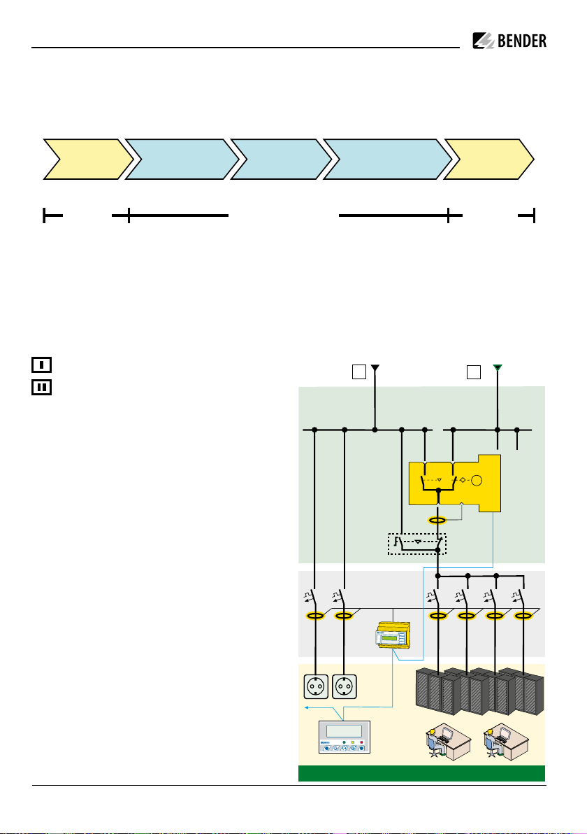
3.3 Application example
Preferred supply
Redundant supply (e.g. generator)
• ATICS-2-63A-DIO: Changeover between
preferred and redundant line
• MK2430/MK800/TM800/CP9xx: Alarm
at at least two points with independent
power supplies for functional safety
• RCMS: RCMS460 or RCMS490 residual
current monitors for localising residual
and operating currents in TT and TN-S
systems
Production Commissioning RecyclingDecommissioningMaintenance
Bender plant operator Bender
III
U1U2
U3I
computing centre
Anlage
betriebsbereit
MK800 NORMAL WARNING ALARM
ESC
TEST MENU
RCMS
ATICS
M

ATICS-DIO_D00080_03_M_XXEN / 04.2021 15
ATICS-…-DIO
3.4 ATICS® tasks
The ATICS® automatic transfer switching device has the following tasks:
• Two-pole or four-pole changeover of the power supply
• Voltage monitoring of the preferred supply (line 1)
• Voltage monitoring of the second supply (line 2)
• Voltage monitoring at the automatic transfer switching device output (line 3)
• Monitoring of the changeover switch for correct switch position
• Internal functional testing, including checking the switching times
• Communication with remote MK… alarm indicator and test combinations, and with TM… or
CP9xx… alarm indicator and operator panels via BMS bus
• Option for adjusting the time delay for the changeover process according to DIN VDE 0100-
710
(VDE 0100 Part 710)
• Possible field of application in systems according to DIN VDE 0100-710 (VDE 0100 Part 710)
with a changeover period ≤ 15 s or even ≤ 0.5 s
3.5 The ATICS® functions
3.5.1 The automatic transfer switching device
If the preferred supply fails, the ATICS® ensures that the power supply is switched over safely.
The switch contacts are arranged offset on a rotating shaft. This design prevents simultaneous switch-
ing of line 1 and line 2. The switch has three positions:
1 Line 1 is connected
0 Both lines are disconnected
2 Line 2 is connected
Either line 1 or line 2 can be set as the preferred line (setting described in „Settings menu 1:
Changeover“ on p. 67 or chapter „Settings menu 5: Dig. input“ on p. 74).
1. In the normal operating condition (fault-free operation) the preferred supply is connected.
The ATICS® switches to the redundant line if:
– The preferred line fails
– The "TEST" button is pressed
– A digital input is configured to "TEST" and this input is enabled
– The setting "Preferred line" is changed to the other line

16 ATICS-DIO_D00080_03_M_XXEN / 04.2021
System description
2. The ATICS® switches from the redundant line back to the preferred line if
– the voltage on the preferred line is restored and the return transfer delay time t(2->1) has
elapsed and no switch-back lock is enabled
– or immediately after pressing the "RESET" button or when the redundant line fails (even when
the switch-back lock is enabled)
– the setting "Preferred line" is changed to the other line
– the digital input is configured to "TEST" and this input is reset
– a test of the automatic transfer switching device is active and the test period has elapsed
I Warning! Malfunction possible if delay times are not adjusted.
The response delay t(on), the return transfer delay time t(2->1), the delay on release t(off) and the
dead time t(0) of the ATICS® are adjustable and must be adjusted to the requirements of the specific
case, the short-circuit calculation and the requirements of DIN VDE 0100-710 (VDE 0100-710) for au-
tomatic transfer switching devices (see chapter „Commissioning, settings and testing“ auf S. 43).
The factory settings guarantee a changeover period of t ≤ 0.5 seconds and switching back within 10
seconds when voltage is restored on the preferred supply. Therefore, the ATICS® can be used in IT sys-
tems with a requirement for a changeover period t ≤ 0.5s (IT systems with operating theatre lights, en-
doscopic field illumination in operating theatres or other essential sources of light, etc.).
When there is a short circuit downstream of the automatic transfer switching device, the automatic
transfer switching device must not continually change back and forth between the two lines. This can
occur if the short-circuit current is small and the automatic transfer switching device switches faster
than the short-circuit breaker trips. The ATICS® monitors the load current downstream of the automatic
transfer switching device in order to detect a possible short circuit. If the preferred line fails and a
short-circuit current is detected at the same time, the ATICS® does not switch over immediately but
only once the circuit breaker has tripped.
If the ATICS® detects a supply failure or a fault, an alarm appears on the LCD, the "ALARM" LED lights up,
the alarm relay trips (if set) and this alarm is forwarded to other Bender devices (such as an alarm indi-
cator and test combination) via the BMS bus.
Phase sequence direction errors are detected and indicated on the LC display. Even so ATICS® switches
over to the redundant line.

ATICS-DIO_D00080_03_M_XXEN / 04.2021 17
ATICS-…-DIO
18 ATICS-DIO_D00080_03_M_XXEN / 04.2021
System description
t(off)
1
0
2
t(on)1t(Imp) t(0) t(Imp) 1
2
t(2->1)
*1
0
1
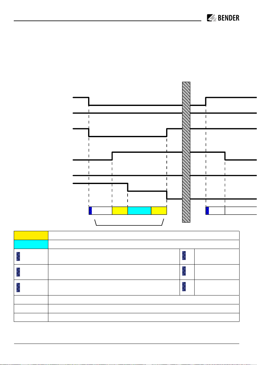
3.5.1.1 Time diagram: Changeover between preferred and redundant line
i
Time diagrams: Times are not shown to scale.
Example: Line 1 is set as preferred line.
Changeover to line 2
if line 1 has failed
Switching back to
line 1 (normal operation with delay on release)
Switching back to line 1
(if line 2 has failed)
Voltage line 1
Voltage line 2
Voltage output ATICS®
Alarm failure line 1
Alarm failure line 2
Switch position
Time delay
t(pulse) Pulse time: 15 … 30 ms
t(0) Dead time
t(on) Response delay ALARM failure voltage line 1
Measuring time:
approx. 50 ms
t(off) Delay on release ALARM failure voltage line 1
Measuring time:
approx. 50 ms
t(on) Response delay ALARM failure voltage line 2
Measuring time:
approx. 50 ms
t(2->1) Return transfer delay time
*1 Changeover period t(1->2) indicated during a test
*2 The return transfer delay time may differ from the changeover period (t(1->2)

ATICS-DIO_D00080_03_M_XXEN / 04.2021 19
ATICS-…-DIO
t(Imp) t(0) t(Imp)
0
1
t(off)1
t(Imp) t(0) t(Imp)
2
0
1
t(2->1)
t(on)2
*2
3.5.1.1 Time diagram: Changeover between preferred and redundant line
i
Time diagrams: Times are not shown to scale.
Example: Line 1 is set as preferred line.
Changeover to line 2
if line 1 has failed
Switching back to
line 1 (normal operation with delay on release)
Switching back to line 1
(if line 2 has failed)
Voltage line 1
Voltage line 2
Voltage output ATICS®
Alarm failure line 1
Alarm failure line 2
Switch position
Time delay
t(pulse) Pulse time: 15 … 30 ms
t(0) Dead time
t(on) Response delay ALARM failure voltage line 1
Measuring time:
approx. 50 ms
t(off) Delay on release ALARM failure voltage line 1
Measuring time:
approx. 50 ms
t(on) Response delay ALARM failure voltage line 2
Measuring time:
approx. 50 ms
t(2->1) Return transfer delay time
*1 Changeover period t(1->2) indicated during a test
*2 The return transfer delay time may differ from the changeover period (t(1->2)

20 ATICS-DIO_D00080_03_M_XXEN / 04.2021
System description
3.5.1.2 Time diagram: Staggered switching after complete power failure
Switching on at staggered intervals after a complete power failure (no voltage on either of the power
supplies) prevents all loads from being switched on at the same time. Switch the ATICS® to position "0"
using an Allen key. When power is restored, the ATICS® switches on the supply again with the set delay
time t(start).
Example: Line 1 is set as preferred line.
Optional: Staggered switching
after complete power failure
Optional: Staggered switching
after complete power failure
Voltage line 1
Voltage line 2
Voltage output ATICS®
Alarm failure line 1
Alarm failure line 2
Switch position
Time delay
t(pulse) Pulse time: 15 … 30 ms
t(start) Switch-on delay after complete power failure
Measuring time: approx.
50 ms
t(off) Delay on release failure voltage line 1
Measuring time: approx.
50 ms
t(off) Delay on release failure voltage line 2
Measuring time: approx.
50 ms
After a complete power failure and restart of the ATICS®, t(off) and t(start) start simultaneously. The time
that is longer determines the behaviour. After switching on, the ATICS® performs a quick measurement
of the voltage with t(off) = 100 ms. If the voltage is within the permissible range, the value set for t(off)
is ignored. If the voltage is too low, the ATICS® waits until the set time t(off) has elapsed.
1
0
2
t(Start) t(Imp)
0
1
0
2
t(off)1
t(Start) t(Imp)
t(off)2
This manual suits for next models
5
Table of contents
Other Bender Power Supply manuals

Popular Power Supply manuals by other brands


Vicon
Vicon 217-00-00 Series Installation and operation guide

Oltronix
Oltronix LS 122R instruction manual

Altronix
Altronix ALTV615DCUL Series installation guide

Whelen Engineering Company
Whelen Engineering Company VPPS2C installation guide

V-TAC
V-TAC 80133970 instruction manual

R&S
R&S NGE100B Series user manual