TDB409015en / Main catalogue part 1 – Insulation monitoring / 05.2011 131
1.7
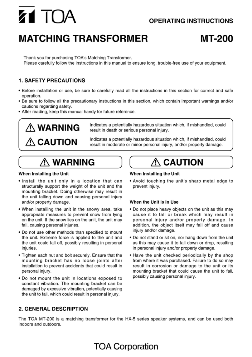
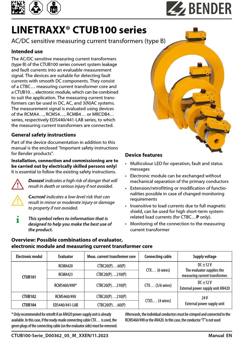
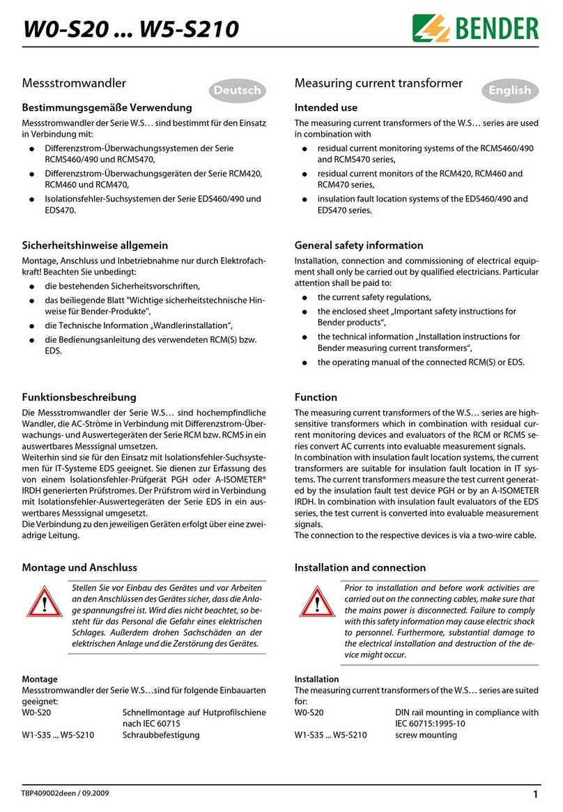
WS… series measuring current transformers – WS…-8000 series measuring current transformers
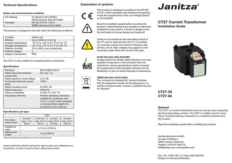
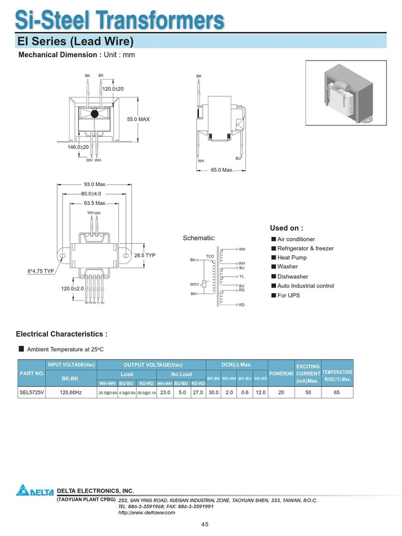
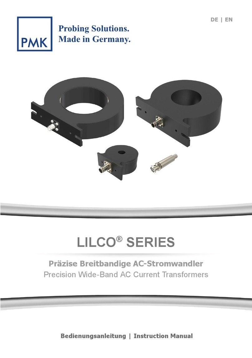
Technical data
Insulation coordination acc. to IEC 60664-1 / IEC 60664-3
Rated insulation voltage 800 V
Rated impulse voltage/pollution degree 8 kV / III
CT circuit WS…
Rated primary residual current 30 mA…10 A
Rated secondary residual current 0.0167 A
Rated transformation ratio Kn10 / 0.0167 A
Rated burden ≤ 180 Ω*
Nominal power 0.05 VA
Frequency range 42 Hz…3 kHz
Rated continuous thermal current Icth 40 A
Rated short-time thermal current Ith 60 x Icth = 2.4 kA / 1 s
Rated dynamic current Idyn 2.5 x Ith = 6.0 kA / 40 ms
CT circuit WS…-8000
Rated primary residual current 30 mA…1 A
Rated secondary residual current 0.000125 A
Rated transformation ratio Kn10 / 0.000125 A
Rated burden 2400 Ω
Nominal power 0.0375 VA
Frequency range 42 Hz…3 kHz
Rated continuous thermal current Icth 6 A
Rated short-time thermal current Ith 60 x Icth = 0.36 kA / 1 s
Rated dynamic current Idyn 2.5 x Ith = 0.9 kA / 40 ms
Environment
Operating temperature -25 °C…+70 °C
Climatic class acc. to IEC 60721
Stationary use (IEC 60721-3-3) 3K5 (except condensation and formation of ice)
Transport (IEC 60721-3-2) 2K5 (except condensation and formation of ice)
Long-time storage (IEC 60721-3-1) 1K5 (except condensation and formation of ice)
Classification of mechanical conditions IEC 60721
Stationary use (IEC 60721-3-3) 3M4
Transport (IEC 60721-3-2) 2M2
Long-time storage (IEC 60721-3-1) 1M3
Connection
Connection screw-type terminals
rigid/flexible/conductor sizes 0.08…2.5 / 0.08…2.5 mm² / 28…12 AWG
Stripping length 8…9 mm
Connection EDS, RCM(S) measuring current transformers
Single wire ≥ 0.75 mm² 0…1 m
Single wire, twisted ≥ 0.75 mm² 0…10 m
Shielded cable ≥ 0.5 mm² 0…40 m
Recommended cable
(shielded, shield on one side connected to L-conductor, not connected to earth) J-Y (St) Y min. 2x0.8
Other
Degree of protection, internal components (IEC 60529) IP40
Degree of protection, terminals (IEC 60529) IP 20
Screw mounting M5 with mounting brackets
Flammability class UL94 V-0
Operating manual WS… TBP409015
Operating manual WS…-8000 TBP108018
Approvals and certifications UL under development, GOST
* The rated burden may vary depending on the respective device
data sheet.
Dimension diagram
Ordering information
Type Internal dimensions Mounting
brackets
Art. No.
WS20x30 20 x 30 mm × B 9808 0601
WS50x80 50 x 80 mm × B 9808 0603
WS80x120 80 x 120 mm × B 9808 0606
WS20x30-8000* 20 x 30 mm × B 9808 0602
WS50x80-8000* 50 x 80 mm × B 9808 0604
Dimensions
Type A B C D E Weight
WS20x30 93 106.15 23 33 64 ≤ 0.6 kg
WS50x80 125 158.15 55 85 96 ≤ 1.04 kg
WS80x120 155 198.15 85 125 126 ≤ 1.4 kg
WS20x30-8000* 93 106.15 33 33 64 ≤ 0.63 kg
WS50x80-8000* 125 158.15 85 85 96 ≤ 1.08 kg
Dimensions in mm
Selection list
Type
RCM420 RCM470 RCMS460
RCMS490
RCMS470 EDS460
EDS490
EDS461
EDS491
EDS470 EDS473 EDS474
WS20x30
×××××--×----
WS50x80
×××××--×----
WS80x120
×××××--×----
WS20x30-8000*
-- -- -- -- -- × -- × ×
WS50x80-8000*
-- -- -- -- -- × -- × ×
* For EDS461/491 and EDS473/474 series insulation fault locators
