BENDIX WS-20 WHEEL SPEED SENSOR User manual

1
®
SD-13-4754
Bendix®WS-20™AntiLock Wheel Speed Sensor
FIGURE 1 - WS-20™ANTILOCK WHEEL SPEED SENSORS
coil.Eachtimeanexcitertoothanditsadjacentspacemove
pastthetipofthe sensor,anACvoltage"cycle"isgenerated.
ThenumberofACcyclesperrevolutionofthevehicle'swheel
depends on the number of teeth in the exciter, which is
programmed into the antilock controller. Using the
programmed data, the controller can calculate "vehicle
speed"byanalyzing the frequency ofACcyclessent by the
speed sensor. (The frequency of AC cycles is directly
proportionaltowheelspeed.)
AC voltage is also proportional to speed, but voltage is not
usedto determine speed. It is only an indication ofACsignal
strength.TheamountofACvoltagegeneratedbyaspecific
speed sensor depends on the distance, or "gap," between
the tip of the sensor and the surface of the exciter. Voltage
increases as the sensor gap decreases.
TheWS-20™wheel speed sensorisinstalled in amounting
block that is affixed to the axle housing. (See Figure 2.)A
springloaded retainerbushingprovidesafrictionfitbetween
themountingblockboreandtheWS-20™sensor.Thefriction
fitallowstheWS-20™sensorto "slide" back andforthunder
force but to retain its position when force is removed. This
DESCRIPTION
The WS-20™wheel speed sensor is an electromagnetic
deviceusedtoobtainvehiclespeedinformationforanantilock
controller.Whenthewheelrotates,thesensor andanexciter
(e.g.rotor or tone wheel)generate a simpleACsignal.This
signalis sent tothecontroller, which analyzes thedataand
commands the antilock system accordingly.
Specifically,the speed sensorconsistsofa coil, polepiece,
and magnet. The exciter is a steel ring or gear-like device
thathasregularly spaced highandlow spots called "teeth."
Thesensor ismounted in afixed position,while the exciter
isinstalledon a rotating membersothat its "teeth"move,in
close proximity, past the tip of the sensor.
TheWS-20™wheelspeedsensorisavailableinboth straight
andright angle versions,toaccommodateaxle/wheelspace
limitations. (See Figure 1.)
OPERATION
Thesensor's magnet andpole piece forma magnetic field.
As an exciter tooth passes by the sensor, the magnetic
field is altered, which generates AC voltage in the sensor
PACKARD 2 PIN
CONNECTOR
90°WS-20™SENSOR
DEUTSCH 2 PIN
CONNECTOR
STRAIGHT WS-20™SENSOR

2
ANTILOCK CONTROLLER
& RELAY
WS-20™SPEED SENSORS
EXCITERS
FRONT WHEEL REAR WHEELS
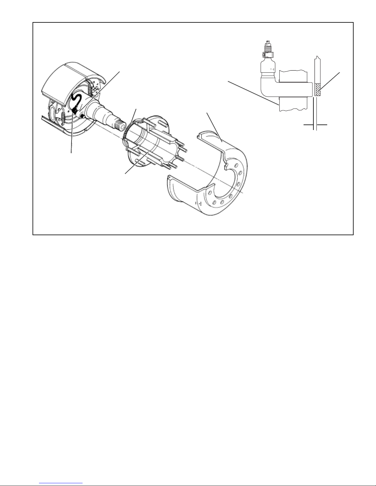
feature allows the WS-20™sensor to "self adjust" after it
has been installed in the mounting block and the wheel is
installed.
When the WS-20™sensor is inserted all the way into the
mounting block and the wheel is installed on the axle, the
hub exciter contacts the sensor, which pushes the sensor
back.Also,normalbearing play will "bump" thesensoraway
from the exciter. The combination of these two actions will
establisharunning clearance or air gap between the sensor
andexciter.
FIGURE 2 - SPEED SENSOR VOLTAGE CYCLE OUTPUT
PEAKTO PEAK
PEAKTO PEAK
HIGHSPEED
LOWSPEED
TECHNICAL INFORMATION
ElectricalConnector- 2 Pin.
OutputVoltage- With a 3,000 Ohm resistor across
thetwosensorleads,outputvoltage
measured on a VOM = .800 VAC
Minimum at 42 Hz, or
approximately5 mph.
SensorGap- 0 to .015 inch.
SensorBody- FormulatedEpoxy;.628" Diameter.
NormalResistance
RangeatRoomTemp- 2000-2500ohms
PREVENTIVE MAINTENANCE
1. Every 3 months; 25,000 miles; 900 operating hours; or
duringthevehiclechassis lubrication interval, makethe
visual inspections noted in "SERVICE CHECKS"
below.
2. Every12months;100,000miles;or3600operatinghours,
performtheOPERATIONALTESTinthis manual.
SERVICE CHECKS
Check all wiring and connectors. Make sure connections
arefreefromvisibledamage.
Examine the sensor. Make sure the sensor, mounting
bracket,andfoundationbrakecomponentsarenotdamaged.
Repair/replaceas necessary.
WARNING! PLEASE READ AND FOLLOW
THESE INSTRUCTIONS TO AVOID
PERSONAL INJURYOR DEATH:
When working on or around a vehicle, the following
general precautions should be observed at all times.
1. Park the vehicle on a level surface, apply the
parking brakes, and always block the wheels.
Always wear safety glasses.
2. Stop the engine and remove ignition key when
working under or around the vehicle. When
working in the engine compartment, the engine
should be shut off and the ignition key should be
removed. Where circumstances require that the
enginebe in operation, EXTREME CAUTION should
be used to prevent personal injury resulting from
contact with moving, rotating, leaking, heated or
electrically charged components.
3. Do not attempt to install, remove, disassemble or
assemble a component until you have read and
thoroughly understand the recommended
procedures. Useonlythepropertoolsandobserve
all precautions pertaining to use of those tools.
4. If the work is being performed on the vehicle’s air
brake system, or any auxiliary pressurized air
systems,make certain todrain the air pressurefrom
FIGURE 3 - TYPICAL ANTILOCK SYSTEM

3
FIGURE 4 - WS-20™WHEEL SPEED SENSOR INSTALLATION
all reservoirs before beginning ANY work on the
vehicle. If the vehicle is equipped with an AD-IS™
air dryer system or a dryer reservoir module, be
sure to drain the purge reservoir.
5. Following the vehicle manufacturer’s
recommendedprocedures, deactivate the electrical
system in a manner that safely removes all
electrical power from the vehicle.
6. Never exceed manufacturer’s recommended
pressures.
7. Never connect or disconnect a hose or line
containing pressure; it may whip. Never remove a
component or plug unless you are certain all
system pressure has been depleted.
8. Use only genuine Bendix®replacement parts,
components and kits. Replacement hardware,
tubing, hose, fittings, etc. must be of equivalent
size, type and strength as original equipment and
be designed specifically for such applications and
systems.
9. Components with stripped threads or damaged
parts should be replaced rather than repaired. Do
not attempt repairs requiring machining or welding
unless specifically stated and approved by the
vehicle and component manufacturer.
10. Prior to returning the vehicle to service, make
certain all components and systems are restored
to their proper operating condition.
REMOVAL
1. Unplug the cable assembly connector from its lead.
Lift the lock tab and pull on the connector until it
disengages.
2. Gently pry the sensor and bushing from the mounting
block.
INSPECTION
Lookforany visible damagetothesensor,cableassembly,
connector,mountingblock,andfoundation brake. Repairor
replaceany damaged components.Make sure theblock is
securely attached to the axle housing.
SENSOR INSTALLATION
1. Forincreased corrosion protection werecommend that
ahigh-temperatureratedsilicon-orlithium-basedgrease
be applied to the interior of the mounting block, the
sensor, and toa new clampingsleeve.
2. Gently push (DO NOT STRIKE) the sensor into the
mounting block hole until it bottoms out on the face of
thetonering. Secure the cableleadwire to the knuckle/
axlehousing 3-6inches fromthe sensor.
SPEED SENSOR
MOUNTING
BLOCK
100 TOOTH SPEED
SENSOR EXCITER
RING
WS-20™SPEED
SENSOR (90 DEG.)
HUB ASSEMBLY
WS-20™SPEED
SENSOR
100TOOTH
EXCITER
MOUNTING
BLOCK
MAX. GAP
(SENSOR TO EXCITER)
.015 INCHES
BRAKE DRUM

4
3. Reconnecttheconnectortothesensorleadbyplugging
itintothe appropriate socket onthepigtailharness, and
pushing until the lock tab snaps into place.
NOTE:It is importantfor the wheelbearingsto be adjusted
perthemanufacturer'srecommendations, toensure
that the antilock function does not shut down as a
resultof excessive wheelend play.
OPERATIONAL TESTING
To test sensor operation, one of two tests can be done.
TEST 1
Drive the vehicle in a safe area to a minimum speed of 15
mph. Be sure to apply the vehicle brakes several times.
Then stop the vehicle and check the LED display on the
Bendix controller. If the dash light is out and the sensor
LED(s)are not illuminated,the sensor isinstalledproperly.
TEST 2
Disconnectthe connector fromthe sensor's socketor from
theattachedlead.Raisethevehiclewheelsoitrotateseasily.
Connectavolt-Ohmmeter (set to readVoltsAC) to the pins
on the sensor or lead and spin the wheel. Output voltage
shouldread greaterthan .800AC. If thewheel isspun at 1
revolution per second (about 7mph) the reading should be
greaterthan 1.0 voltsAC.
Ifthe sensor failsto operate asdescribed,check the wiring
from the controller to the sensor. Make sure all connectors
are properly and tightly installed. Check for frayed or
damaged wires and check and/or reset the sensor air gap
(distance from sensor tip to exciter ring) as described in
thismanual.Foradditionaltroubleshootinginformation,see
thetroubleshootingprocedureforthespecificantilocksystem
in use.
BW1662 © 2005 Bendix Commercial Vehicle Systems LLC All rights reserved. 1/2005 Printed in U.S.A.
Other BENDIX Accessories manuals