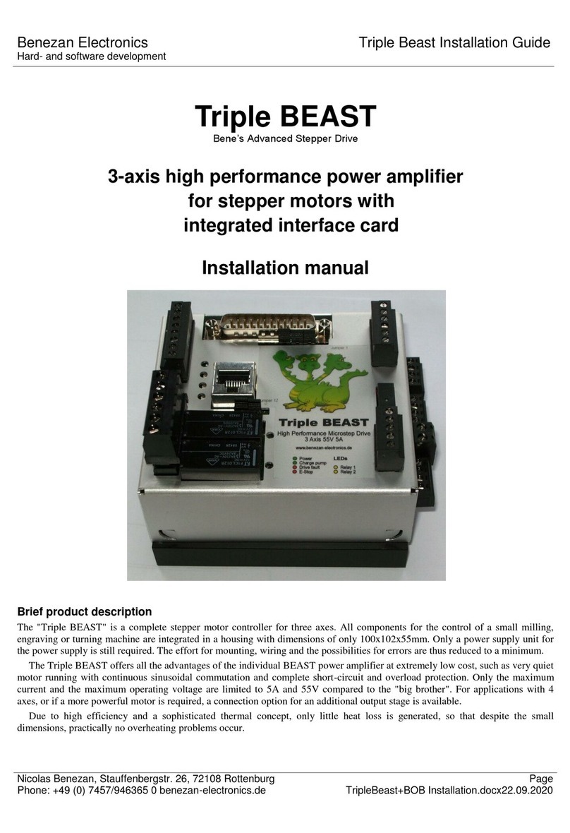
Benezan Electronics BEAST User manual

Benezan ElectronicsBEAST Stepper motor power stage
Hard- and software developmentInstallation Guide
Nicolas Benezan, Stauffenbergstr. 26, 72108 RottenburgPage 1
Phone: +49 (0) 7457/946455 Beast1D-Installationwww.benezan-electronics.de.docx 22.09.2020
BEAST
Bene’s Advanced Stepper Drive
High power driver for stepper motors
improved, digital version
Installation manual
Brief product description
The "BEAST" is a powerful and compact stepper motor output stage for applications in CNC and automation
technology. With its wide range of adjustable phase current from 1.8 to 1 0A, it can be used for all common
two-phase motors from 56mm (NEMA23) to 11 0mm (NEMA42) flange size.
The output stage is constructed with discrete MOSFETs. The high supply voltage range up to 80V offers
significant advantages over most integrated power stage ICs at higher speeds and more safety margin against damage
from voltage spikes. An integrated short-circuit protection makes the electronics insensitive to the most common
errors.
Microstep control and a new type of continuous sinusoidal commutation significantly reduces noise and resonance
at low speeds. Active damping also prevents vibrations at high speeds and enables very high speeds that cannot be
achieved with low-cost solutions.
Targeted circuit measures such as optical decoupling of all control signals and limited edge steepness of the circuit
breakers (Active Slope Control) ensure maximum interference immunity and minimum interference emission. This
increases reliability and helps you to comply with EMC regulations. Of course the device also complies with the
latest RoHS regulations.

Benezan ElectronicsBEAST Stepper motor power stage
Hard- and software developmentInstallation Guide
Nicolas Benezan, Stauffenbergstr. 26, 72108 RottenburgPage 2
Phone: +49 (0) 7457/946455 Beast1D-Installationwww.benezan-electronics.de.docx 22.09.2020
1 Safety Instructions
The BEAST stepper motor output stage may only be installed and commissioned by qualified personnel. Please read
the operating instructions carefully and follow all instructions exactly. Improper installation or operation of the
device can cause damage to the electronics or the machine and can result in dangers to the health of the operating
personnel. The system manufacturer, who assembles the power amplifier and other components to form the overall
system, and the system operator are responsible for compliance with the legal regulations.
Caution: Danger to life! The device can be operated with voltages up to 80V. In the event of a fault, voltage
peaks of up to 100V may occur briefly. If you operate the system with more than 60V, the installation and
commissioning may only be carried out by a trained electrician or must be approved by such an electrician. No
liability is accepted for damage or injury resulting from disregard of safety regulations or improper use.
Always use a power supply unit with potential separation (no autotransformer or variac)! The machine, motor and
housing must be grounded in accordance with regulations.
2 System requirements
To obtain a functional drive system, the following components are required in addition to the BEAST power
amplifier:
1. A two-phase stepper motor with a rated current between 1.8 and 10A. Three- or five-phase motors or
high-impedance motors from printers and disk drives are not suitable.
2. A power supply unit for the voltage supply. with an output voltage between 24 and 80V. Stabilization is not
absolutely necessary. More detailed selection criteria are given in chapter 3.2.
3. A signal source for the step and direction signal to control the power amplifier. This can be a PC with
appropriate software, an external CNC control (e.g. USB-CNC), or for test purposes also a frequency generator.
2.1 Recommended motors
The table below lists some recommended combinations with motors from Benezan Electronics. The applications
mentioned above only represent an approximate selection. If you wish a more precise calculation of the drives, please
contact Benezan Electronics.
Motor Type
Dimensions
Phase current
Operating voltage
Application
HS56-0818
56 x 56mm
1,8A
30..48V
Miniature machines,Pick&Place,
Pen plotter
HS56-1442
56 x 76mm
4,0A
36..50V
smaller milling machines in aluminium
profile-
Design
HS60-2150
60 x 90mm
5,0A
48..55V
HS86-3263
86 x 78mm
6,0A
48..70V
Milling machines for metalworking,
larger portal machines
HS86-5880
86 x 118mm
8,0A
60..80V
HS86-8588
85 x 156mm
9,0A
70..80V1
The BEAST power amplifier also works together with many motors from other manufacturers. Please note, however,
that under certain circumstances full performance may not be achieved.
1 with Big-BEAST up to 160V

Benezan ElectronicsBEAST Stepper motor power stage
Hard- and software developmentInstallation Guide
Nicolas Benezan, Stauffenbergstr. 26, 72108 RottenburgPage 3
Phone: +49 (0) 7457/946455 Beast1D-Installationwww.benezan-electronics.de.docx 22.09.2020
3 Installation
3.1 Assembly
The output stage is designed for mounting on a 35mm DIN rail ("top-hat rail"). Hook the power amplifier into the rail
with the terminal side facing up, then press the bottom side with the control connection firmly onto the rail until it
snaps into place. Alternatively, it can also be mounted from the rear side with M3 screws or spacer bolts on a
mounting plate. Since the output stage becomes more or less hot during operation depending on the motor current,
the following rules must be observed during installation:
Make sure that there is free air circulation. The distance to other devices, housing wall, cable ducts, etc. should
be at least 2 cm on all sides.
If possible, the heat sink should be mounted vertically with vertical fins.
For horizontal mounting and motor current >4A, for vertical mounting >6A or at an ambient temperature
>40°C, forced cooling (fan) is required.
With a motor current >8A forced cooling is always necessary.
3.2 Power supply connection
The supply voltage must be between 24 and 80V. A stabilized power supply is not necessarily necessary, an
unregulated power supply consisting of transformer, rectifier and filter capacitor is completely sufficient. Please
note, however, that the voltage range must be maintained even with mains and load fluctuations (usually ±10%).
The maximum current with which the power supply unit is loaded is approx. 2/3 of the motor current. However,
the permanent load is lower in most applications. For the operation of 3 motors with 4A each, for example, a power
supply unit with 3 x 4A x 2/3 = 8A peak current and about 5A continuous load capacity is sufficient. An electrolytic
capacitor with about 1000μF per A motor current is recommended to keep voltage fluctuations caused by mains hum
and short load changes small. A little more won't hurt either, but the capacitor should not be too big either, otherwise
the current peaks in the rectifier and transformer will be too big.
Connect the positive pole of the power supply to terminal 1 (labelled 24..80V DC) and the negative pole to
terminal 2 (labelled Power Ground). Caution, wrong polarity can damage the power amplifier, especially if the
power supply does not have a fast fuse or current limiter
If necessary, several BEAST power amplifiers can be operated in parallel on one power supply unit. Please note
please ensure that the negative connection (Power Ground) is connected to the heat sink and therefore automatically to
the housing (potential earth) is connected. The connecting cables between the power supply unit and the power
amplifiers should be laid in a star shape and as short as possible, i.e. each power amplifier should have its own direct
connection to the power supply unit.
3.3 Motor connection
The output stage is suitable for the operation of two-phase motors. These usually have four or eight connections. For
motors with eight connections, two windings can be connected in parallel or in series. The following formula can be
helpful as a decision aid - serial or parallel: The supply voltage should be in the range of 10 to 25 times the rated
motor voltage. If the nominal voltage is not given, it can be calculated by multiplying the winding resistance by the
nominal current. Example:
Motor data: 8 connections, 0.8Ωper winding, rated current 3A per winding, 6A parallel
parallel connection 2x0.8Ωgives 0.4Ω* 6A = 2.4V Series connection: 2x0.8Ωgives 1.6Ω
* 3A = 4.8V
Line voltage 48V = 20 x 2.4V = 10 x 4.8V
In this case both types of connection would be possible. However, parallel connection allows higher speeds, and is
therefore usually preferred.
Motors with 6 terminals can also be used, but this is not recommended as these are mostly older models designed
for unipolar operation with obsolete power amplifiers. Old motors, which can usually be recognized by their round,
cylindrical housing, are not designed for microstep operation and exhibit increased vibration and reduced torque.
Connect one winding of the motor to terminals 3 and 4 (A-B), the second winding to terminals 5 and 6 (C-D). The
polarity and sequence is irrelevant for the function, but determines the direction of rotation of the motor. If the motor
turns in the wrong direction, this can be corrected by reversing the polarity of one (not both) of the windings.
Caution, never disconnect the terminal connection to the motor or power supply unit when the power supply unit

Benezan ElectronicsBEAST Stepper motor power stage
Hard- and software developmentInstallation Guide
Nicolas Benezan, Stauffenbergstr. 26, 72108 RottenburgPage 4
Phone: +49 (0) 7457/946455 Beast1D-Installationwww.benezan-electronics.de.docx 22.09.2020
is switched on. The output stage is protected against interruption of the motor cable. However, a rotating motor acts
like a generator when switched off and returns energy to the output stage. It cannot absorb the energy if the
connection to the power supply has been disconnected and may be damaged. Furthermore, the contacts of the
connectors are affected by sparking.
3.4 Settings
The phase current is selected with the rotary coding switch "Current Set". No measuring device and no external
components are required, only a screwdriver. The phase current corresponds to the maximum current through a
winding or the magnitude value of the current vector (i.e. not the rms value) according to the following table:
Switch position
Phase current
Switch position
Phase current
0
1,8A
8
5,0A
1
2,0A
9
5,5A
2
2,4A
A
6,0A
3
2,8A
B
6,5A
4
3,2A
C
7,0A
5
3,6A
D
8,0A
6
4,0A
E
9,0A
7
4,5A
F
10,0A
Switch No.
Meaning
1
Resolution: 1/5, 1/10, 1/20, 1/40
Microstep
2
3
automatic current reduction
4
Waveform sine + harmonic
Attention Be sure to set the correct phase current before switching on the power supply. Too high a current - even
for a short time - can damage the motor. If you do not need the full torque of the motor, you can also set a slightly
lower current. This significantly reduces heat generation. However, do not set less than 70% of the rated current,
otherwise the motor may not run smoothly.
The BEAST output stage has a current reduction which can either be automatic or controlled by an input signal. With
automatic current reduction, the phase current is reduced to approx. 66% of the set maximum value if no step signal
has been received for longer than approx. 0.6s. This reduces the losses and thus the heating of the motor to less than
half, while still sufficient torque is available to hold the position
With heavy loads, such as CNC metalworking, the automatic current reduction is not recommended, because
otherwise, with straight lines parallel to the axes, the non-moving axis may lose steps when lateral forces are applied.
To avoid this, the explicit current reduction via the input signal should be selected here. The control then only
activates the current reduction if all Axles stationary.
The Piano DIP switches have the following assignment (pressing down activates the option):
Switch No. 3 activates the automatic current reduction. If it is pressed, the power stage automatically reduces the
current to 66% of if no step has been executed for more than 0.6s. If it is switched off, the current reduction is
activated via the input of the RJ45 socket.
Switch #4 is used to adjust the waveform of the motor current. Some motor types do not have an exact sine wave
but a waveform slightly distorted in the direction of a triangle. The optimal waveform can be determined
experimentally, and leads to a reduction of vibrations in certain speed ranges.
Switches 1 and 2 (left) are used to set the resolution. The following combinations are possible.
Switch position
(down = 1)
Resolution
Microstep
Steps/revolution
at 1,8°/step
V V
0 0
1/5
1000

Benezan ElectronicsBEAST Stepper motor power stage
Hard- and software developmentInstallation Guide
Nicolas Benezan, Stauffenbergstr. 26, 72108 RottenburgPage 5
Phone: +49 (0) 7457/946455 Beast1D-Installationwww.benezan-electronics.de.docx 22.09.2020
V W
0 1
1/10
2000
W V
1 0
1/20
4000
W W
1 1
1/40
8000
3.5 Status display
The output stage indicates the current status with 3 LEDs. The meaning of the possible combinations is listed in the
following table:
Colour combination
Meaning
Cause
-
switched off
Operating voltage too low or sleep mode
green
Operation, full current
-
yellow
Operation, current reduction
no step signal or current reduction signal
red
Overvoltage
Braking energy too high or power supply unsuitable
flashing red
Overheating
Ambient temperature too high or ventilation impeded
red/yellow flashing
Overcurrent
Short circuit, wrong connection or motor defective
flashing yellow
Current too low
no motor connected or motor cable interrupted
3.6 Signal connections
The step and direction signals are connected to the RJ-45 socket marked "Command Input". The power amplifiers
can be connected directly to the Benezan Electronics breakout board with standard Ethernet patch cables (1:1, no
crossover or X!). The wire colours apply when using standard Cat5 Ethernet patch cables (e.g. from Reichelt). Pin 1
is located on the side of the housing corner.
BEAST RJ-45 socket
Wire colour
8
Status output -
brown
7
Status output +
white/brown
6
Step Input +
green
5
Direction entrance -
white/blue
4
Direction entrance +
blue
3
Step Input -
white/green
2
Current reduction -
orange
1
Current reduction +
white/orange
If you are not using a breakout board with compatible RJ45 jacks, you can connect the power amplifier as follows:
All negative inputs are connected to ground and the positive inputs are driven with a TTL or CMOS signal
All positive inputs are connected to +5V or +3.3V and the negative inputs are driven by a low-active driver
(or open collector).
Positive and negative inputs are controlled with complementary drivers (RS422). The status output is
conductive in normal operation (+ and - connected), interrupted in case of error message. If the negative
output is connected to ground, an open-collector signal with 0=Ok and 1=error is obtained at the positive
output.
The step signal reacts to the positive edge, i.e. when pin 3 becomes positive with respect to pin 6. When changing
direction, a distance of min 2µs should be kept to the preceding and following positive edge.
The current reduction is active (66%) when voltage is applied to the input. If no or automatic lowering is desired,
the input can be left open.
3.7 Stop on error
For machines with several axes, it is essential to provide a circuit that informs the central control about possible error
states of individual axes and ensures controlled stopping of all axes triggers. With milling machines, for example,
damage to the workpiece and the machine can occur if only one axis and the others would drive on. If the BEAST
power amplifiers are connected to a suitable breakout board, the status outputs of all axes are automatically linked
and switched to the alarm input of the controller. If other controllers are used, a small external circuit is necessary.

Benezan ElectronicsBEAST Stepper motor power stage
Hard- and software developmentInstallation Guide
Nicolas Benezan, Stauffenbergstr. 26, 72108 RottenburgPage 6
Phone: +49 (0) 7457/946455 Beast1D-Installationwww.benezan-electronics.de.docx 22.09.2020
The figure above shows two circuit examples, one for 24V level (e.g. PLC systems) and one for 5V level (PC parallel
port, Mach3 without breakout board or from another manufacturer). The status outputs of the BEAST output stages
are connected in series. A fault in at least one output stage, the interruption of a cable or a power failure will certainly
lead to an alarm message to the control system.
The pull-up resistor R1 can be omitted in most cases because it is already internally integrated in the parallel port
of the PC. This means that in most cases no external 5V supply is necessary. Up to 5 axes can be connected in series.
3.8 Sleep mode
In order to ensure a safe stop, e.g. in case of an emergency stop or open safety doors, it is often necessary to
disconnect the motors from the power supply. A shutdown via software or a (non-redundant) enable signal is not
sufficiently safe. However, if the supply voltage is switched off completely, the disadvantage is that the current
microstep position is lost and the motor jumps to the next full step when it is switched on again. As a result, a
reference run would be necessary after each emergency stop or door opener, which takes time and is an unnecessary
source of error.
With the BEAST power amplifier this problem can be circumvented with the sleep mode. When the supply voltage is
reduced to 12V, the motor is de-energized, but the processor remains active and keeps the current position. When the
full operating voltage is switched on again, no steps are lost and work can be continued without reference run.
It is recommended to connect a fuse (<1A) and a diode in series in the positive lead of the 12V power supply. This
protects the 12V power supply from the higher operating voltage. It also ensures that regardless of the correct
function of the power stage, the motor cannot start unintentionally in sleep mode, as increased current consumption
causes the fuse to blow.

Benezan ElectronicsBEAST Stepper motor power stage
Hard- and software developmentInstallation Guide
Nicolas Benezan, Stauffenbergstr. 26, 72108 RottenburgPage 7
Phone: +49 (0) 7457/946455 Beast1D-Installationwww.benezan-electronics.de.docx 22.09.2020
4 New features
The present version of the BEAST power amplifier has been improved once again.
With the exception of the connectors and switches, all components - even the power transistors - are 100%
SMD-assembled. This increases reliability and improves heat dissipation.
The resolution is selectable from 1/5 to 1/40 microstep. This means that the output stage can also be used for
applications in which the step frequency is limited by the software or which require extreme resolution (e.g.
camera tracking).
The waveform is switchable between pure sine and sine with harmonic content. This reduces the vibrations
of some engine types.
The engine noise at standstill has been reduced.
The resonance damping has been improved, the sometimes rough running no longer occurs with some
engine types and certain frequencies.
The output stage detects interruptions in the motor cable. In case of cable breakage, the system can be
switched off in a defined manner.
The resonance damping can no longer be switched off, and the direction of rotation can no longer be
reversed by a switch (if necessary, reverse the polarity of the motor winding).
Sleep mode prevents step loss in case of emergency stop
(see3.8).
4.1 Compatibility
Of course, the new version is compatible with earlier versions. If you replace BEAST power amplifiers in an existing
system, set the DIP switches to a resolution of 1/10 microstep (switch no. 1 off, switch no. 2 pressed). Set the
automatic current reduction (switch no. 3) in the same way as the previous one, and set the waveform to pure sine
wave (switch no. 4 off). If you have used the direction of rotation reversal with the old power amplifier, you must
now do this by reversing the polarity of the direction signal in the control software or by reversing the polarity of a
motor winding.
It is no longer necessary to adjust the motor size or switch off the resonance damping, because the damping
automatically adapts to the motor.

Benezan ElectronicsBEAST Stepper motor power stage
Hard- and software developmentInstallation Guide
Nicolas Benezan, Stauffenbergstr. 26, 72108 RottenburgPage 8
Phone: +49 (0) 7457/946455 Beast1D-Installationwww.benezan-electronics.de.docx 22.09.2020
5 Technical data
5.1 Absolute limit values
The following parameters must not be exceeded under any circumstances to prevent damage to the device:
Parameters
min.
max.
Unit
Operating voltage
-0.5
+100
V
Storage temperature
-40
+85
°C
Operating temperature
-20
+70
°C
Voltage at signal inputs
-6
+6
V
Voltage at status output
-5
+30
V
Current at status output
20
mA
Potential difference between supply voltage and
Signal inputs (optical coupler)
-100
+100
V
5.2 Electrical connection values
Parameters
min.
max.
Unit
Operating voltage
+24
+80
V
Current consumption without motor
50
mA
Ambient temperature
0
+50
°C
Level logical 0 for signal inputs
-5
+0.8
V
Level logic 1 for signal inputs
+3
+5.5
V
Current consumption signal inputs at +5V
4
122
mA
Current consumption signal inputs at +3.3V
3
6
mA
Pulse width for step signal
2
µs
Setup time Direction signal valid until step3
2
µs
Level logical 0 for status output
0.8
V
Crotch frequency
0
200
kHz
Delay time automatic current reduction
0.5
0.7
s
Threshold over temperature
70
85
°C
Current control accuracy
-10
+10
%
Wire cross section for terminals
0.5
2.5
mm²
Number of microsteps per full step
5, 10, 20, 40
-
Microsteps/revolution for standard motor4
1000, 2000, 4000,
8000
-
5.3 Dimensions
Parameters
typ.
Unit
Length (incl. clamps)
112
mm
Height (without top-hat rail)
63
mm
Width
48
mm
2 This is the maximum current that flows when 5V is applied directly. A normal CMOS driver (e.g. 74HC245) with
8mA driver power is still sufficient to drive the input at 4.5V.
3 Step is executed on rising edge, i.e. transition from logical 0 to logical 1
4 Standard motor: 1 ,8°/full step, 200 full steps/revolution
Table of contents
Other Benezan Electronics Control Unit manuals
Popular Control Unit manuals by other brands
M-system
M-system R3Y-SS8 instruction manual
Honeywell
Honeywell RV181 Installation instruction

Watts
Watts 980GD-16-19 Installation, operation and maintenance manual

Telit Wireless Solutions
Telit Wireless Solutions GE864 DUAL V2 Hardware user's guide
Quectel
Quectel LTE-A Series Hardware design
Bosch
Bosch Rexroth IndraControl VCP 25.2 Project planning manual
