Beninca CBY.24V User manual

L8542722
11/2013 rev 1
CBY.24V
UNIONE NAZIONALE COSTRUTTORI
AUTOMATISMI PER CANCELLI, PORTE
SERRANDE ED AFFINI

1
2
NTC (not used)
CBY.24V
12V
DA.BT2/DA.BT6
Pb Battery
12V
+ -
CBY.24V
NiMh Battery
RED
BLACK
NTC+ -
BLUE
2

CENTRALE DI COMANDO
CONTROL UNIT
STEUEREINHEIT
CENTRALE DE COMMANDE
CENTRAL DE MANDO
CENTRALKA STEROWANIA
Nero
Black
Schwarz
Noir
Negro
Czarny
Nero
Black
Schwarz
Noir
Negro
Czarny
Rosso
Red
Rot
Rouge
Rojo
Czerwony
Rosso
Red
Rot
Rouge
Rojo
Czerwony
3
4
24sc
VMsc
VMtrs
24trs
0trs
0sc
CBY.24V
CENTRALE DI COMANDO
CONTROL UNIT
STEUEREINHEIT
CENTRALE DE COMMANDE
CENTRAL DE MANDO
CENTRALKA STEROWANIA
24V
0
0
0
230
24
3

24sc
VMsc
VMtrs
24trs
0trs
0sc
CBY.24V
CENTRALE DI COMANDO
CONTROL UNIT
STEUEREINHEIT
CENTRALE DE COMMANDE
CENTRAL DE MANDO
CENTRALKA STEROWANIA
24V VMOT
0
0
0
230
V2
24
V1
V3 V1 ≥ 23V
5
4

CBY.24V ITALIANO
Scheda caricabatteria per il collegamento delle batterie di emergenza a centrali di comando per motori 24Vdc.
E’ possibile utilizzare sia batterie al piombo sia batterie NiMh:
- Collegamento delle batterie al piombo mod. DA.BT2/DA.BT6
In figura 1 è illustrato il collegamento delle batterie da 12V al piombo. Il terminale NTC non va collegato.
- Collegamento delle batterie NiMh
In figura 2 è illustrato il collegamento delle kit batterie NiMh da 24V.
IMPORTANTE: E’ necessario tagliare il connettore rapido delle batterie NiMh, per evitare cortocircuiti, tagliare un filo alla volta.
Collegare i tre fili rispettando i colori: Rosso:+ / Nero:- / Blu:NTC (sensore termico).
Per il collegamento alla centrale di comando sono disponibili 3 diverse modalità a seconda del tipo di centrale:
- Centrale con connettore rapido per caricabatterie:
Se la centrale dispone di connettore rapido per il caricabatterie è sufficiente collegare con il cavo fornito in dotazione i due connettori come
evidenziato in Figura 3.
NOTA: Alcune centrali dispongono di connettori rapidi per altri utilizzi, ad esempio per ricevitori radio.
Verificate sul manuale fornito con la centrale l’effettiva presenza del connettore rapido per caricabatterie, prima di procedere al cablaggio.
- Centrale con ingressi 0V/24V:
Se la centrale è collegata al trasformatore per mezzo dei due soli collegamenti (0V/24V), scollegate il trasformatore e, dopo aver rimosso la copertura
del morsetto, effettuate i cablaggi evidenziati in Figura 4. e’ necessario effettuare un ponticello tra i morsetti VMTRS e 24 TRS.
- Centrale con ingressi 0V/24V e ingresso velocità motore:
Alcune centrali 24V sono dotate di un collegamento aggiuntivo che regola la velocità del motore su diversi valori disponibili nel trasformatore.
In questo caso scollegate il trasformatore e, dopo aver rimosso la copertura del morsetto, effettuate i cablaggi evidenziati in Figura 5.
Nella tabella di seguito viene descritta in dettaglio la morsettiera.
ATTENZIONE!
Durante il funzionamento in assenza di rete, l’uscita accessori 24Vac della centrale, risulta polarizzata.
E’ indispensabile verificare il corretto collegamento degli accessori, come riportato nel manuale istruzioni della centrale di comando.
Funzioni Ingressi/Uscite Caratteristiche Tecniche:
+ + 24Vdc dalla batteria di emergenza Corrente di carica 200mA
- - 24Vdc dalla batteria di emergenza Tensione di carica 27,2 Vdc
NTC Sensore Termico (solo per batterie NiMh) Tempo di carica
(per batterie 2Ah) 10 ore circa
0sc Collegare al connettore 0V della centrale
0trs Collegare al secondario 0V del trasformatore
24trs Collegare al secondario 24V del trasformatore (da 23 a 28Vac).
VMtrs
Collegare al secondario del trasformatore (min. 23V).
ATTENZIONE!: Seleziona la velocità di funzionamento del motore.
Fate riferimento alle istruzioni della centrale di comando per il cor-
retto collegamento.
VMsc Collegare al connettore VMot della centrale
24sc Collegare al connettore VAux della centrale.
Diagnostica
Sulla scheda sono presenti due LED che indicano lo stato del sistema:
STATO CARICABATTERIE LED VERDE LED ROSSO
Funzionamento normale - batteria non in fase di carica Lampeggio continuo Spento
Batteria in fase di carica Acceso Acceso
Funzionamento a batteria Lampeggio veloce Spento
Funzionamento a batteria (con batteria scarica e carico scollegato) 1 Lampeggio breve con pausa 1 Lampeggio breve con pausa
Verifica batteria scollegata Lampeggio veloce Lampeggio veloce
Batteria NiMh in protezione termica Acceso Lampeggio veloce
Note
Durante il normale funzionamento di rete la scheda provvede al mantenimento della carica delle batterie.
Nel caso di assenza di rete la scheda fornisce alimentazione attraverso le batterie. Un fusibile F10A protegge la centrale durante il funzionamento
con batteria di emergenza.
La batteria tampone funziona fino a che, scaricandosi progressivamente,non raggiunge il valore di 18V.Al raggiungimento di questo valore la batteria
viene scollegata.
5

CBY.24V ENGLISH
Battery charger card for the connection of emergency batteries to control units for 24VDC motors.
Either lead batteries or NiMh batteries can be used:
- Connection to lead batteries model DA.BT2/DA.BT6
Figure 1 shows the connection of lead, 12V batteries. Terminal NTC must not be connected.
- Connection of NiMh batteries
Figure 2 shows the connection of NiMh, 24Vbatteries.
IMPORTANT: The rapid connector of NiMh should be cut. Cut one wire at a time to avert any short-circuits.
Connect the three wire while respecting the colours:
Red: +/Black: - /Blue: NTC (thermal sensor).
As regards the connection to the control unit, 3 different ways are available, according to the type of control unit:
- Control unit with rapid connector for battery charger:
If the control unit is provided with a rapid connector for the battery charger, it is sufficient to connect the two connectors with the cable supplied,
as shown in Figure 3.
NOTE: Some control units are provided with rapid connectors for other uses, e.g. radio receivers.
Before proceeding to the wire connection, check on the user’s manual supplied with the control unit that the rapid connector is actually supplied
for battery chargers.
- Control unit with 0V/24V inputs:
If the control unit is connected to the transformer through only two connections (0V/24V), disconnect the transformer and, after removing the terminal
cover, carry out the wire connections as shown in Figure 4. Terminals VMTRS and 24 TRS should be short-circuited.
- Control unit with 0V/24V inputs and motor speed input:
Some 24V control units are equipped with an additional wire connection which regulates the motor speed to the various values available in the
transformer.
In this case, disconnect the transformer and, after removing the terminal cover, carry out the wiring as shown in Figure 5.
The following table describes the terminal board in detail.
CAUTION!
During operation, should a power failure occur, the 24V accessory output of the control unit is polarised.
It is mandatory to check the correct operation of accessories, as described in the user’s manual of the control unit.
Input/Output functions Specification:
+ + 24VDC from the emergency battery Charge current 27.2 VDC
- - 24VDC from the emergency battery Charge voltage 27,2 Vdc
NTC Thermal sensor (for NiMh batteries) Charge time
(for 2Ah batteries) 10 ore circa
0sc Connect to 0V connector of the control unit
0trs Connect to 0V secondary terminal of the transformer
24trs Connect to the 24V secondary terminal of the transformer
(from 23 to 28VAC).
VMtrs
Connect to secondary terminal of the transformer (23V
min.).
CAUTION!: Select the motor operating speed. To perform a
correct connection, make reference to instructions of the
control unit.
VMsc Connect to the Vmot connector of the control unit
24sc Connect to the VAux of the control unit.
Diagnostics
The board features two LEDs that indicate the status of the system:
CHARGER STATUS GREEN LED RED LED
Normal operation - battery not charging Continuous flashing Off
Battery charging On On
Battery Operation Fast blinking Off
Battery operation (with battery and load disconnected) 1 short blink with pause 1 short blink with pause
Check battery disconnected Fast blinking Fast blinking
NiMh battery in thermal protection On Fast blinking
Notes.
During the normal network powering, the card maintains the battery charged.
If a power failure occurs, the card powers the system through the batteries.A F10A fuse protects the control unit during operation with the emergency
battery.
The buffer battery operates until 18V is reached. The charge is reduced progressively. When this value is reached, the battery is disconnected.
6

CBY.24V DEUTSCH
Karte des Batterieladegeräts, um Reservebatterien an die Steuerzentralen von Motoren zu 24Vdc zu schließen.
Es können sowohl Blei- als auch NiMh-Batterien verwendet werden:
- Anschluss der Bleibatterien Mod. DA.BT2/DA.BT6
Die Abbildung 1 zeigt den Anschluss der Bleibatterien zu 12V. Der Verbinder NTC muss nicht angeschlossen werden.
- Anschluss der NiMh-Batterien
Die Abbildung 2 zeigt den Anschluss des Batteriesets NiMh zu 12V.
WICHTIG: Der Schnellverbinder der NiMh-Batterien muss abgeschnitten werden, um Kurzschlüsse zu vermeiden.
Einen Leiter nach dem anderen durchschneiden.
Die drei Leiter den Farben gemäß anschließen:
Rot:+ / Schwarz:- / Blau:NTC (Wärmefühler).
Je nach Steuerzentrale kann der Anschluss auf drei verschiedene Weisen erfolgen:
- Zentrale mit Schnellverbinder für das Batterieladegerät:
Wenn die Zentrale über einen Schnellverbinder für das Ladegerät verfügt, genügt es die beiden Verbinder mit dem mitgelieferten Kabel wie in Abb.
3 gezeigt, anzuschließen.
BEMERKUNG: Einige Zentralen sich mit Schnellverbinder für andere Anwendungen, wie Funkempfänger ausgestattet.
Prüfen Sie anhand des mitgelieferten Handbuchs, ob die Zentrale über einen Schnellverbinder für das Ladegerät verfügt, bevor Sie die Anschlüsse
vornehmen.
- Zentrale mit Eingängen 0V/24V:
Wenn die Zentrale an einem Transformator durch nur zwei Anschlüsse (0V/24V) verbunden ist,den Transformator abtrennen, die Klemmenabdeckung
abnehmen und die Anschlüsse laut Abbildung 4 vornehmen. Die Klemmen VMTRS und 24 TRS müssen überbrückt werden.
- Zentrale mit Eingängen 0V/24V und Eingang für Motorgeschwindigkeit:
Einige Zentralen zu 24V verfügen über einen zusätzlichen Anschluss, der die Motorgeschwindigkeit regelt und den unterschiedlichen Werten des
Transformators anpasst.
In diesem Fall, zuerst den Transformator abtrennen und die Klemmenabdeckung abnehmen, dann die Anschlüsse laut Abb. 5 vornehmen.
In der nachstehenden Tabelle wird die Klemmleiste näher beschrieben:
ACHTUNG!
Während des Betriebs ohne Stromversorgung durch das Netz, ist der Ausgang Zubehör 24Vac der Zentrale polarisiert.
Der richtige Anschluss des Zubehörs muss laut den Gebrauchsanweisungen des Handbuchs geprüft werden.
Funktionen Eingänge/Ausgänge Technische Eigenschaften
+ + 24Vdc der Reservebatterie Ladestrom 200mA
- + 24Vdc der Reservebatterie Ladespannung 27,2 Vdc
NTC Wärmefühler (nur für NiMh-Batterie) Ladezeit
(für Batterie 2Ah) 10 Stunden circa
0sc An den Verbinder 0V der Zentrale schließen
0trs An die Sekundärwicklung 0V des Trafos schließen
24trs An die Sekundärwicklung 24V des Trafos (zu 23 bis 28Vac)
schließen
VMtrs
An die Sekundärwicklung des Trafos (min. 23V) schließen
ACHTUNG! Regelt die Geschwindigkeit des Motors. Für die
Anschlüsse beziehen Sie sich bitt auf die Anweisungen der
Steuerzentrale.
VMsc An den Verbinder VMot der Zentrale schließen
24sc An den Verbinder VAux der Zentrale schließen
Diagnose
Das Board verfügt über zwei LEDs, die den Status des Systems anzuzeigen:
STATE LADEGERÄT grüne LED rote LED
Normalbetrieb - Batterie wird nicht geladen Dauerblinken aus
Das Laden der Batterie auf auf
Betrieb mit Batteriestrom Schnelles Blinken aus
Batteriebetrieb (mit Batterie und Last getrennt) Blinkt mit 1 Pause Blinkt mit 1 Pause
Batterie getrennt prüfen Schnelles Blinken Schnelles Blinken
NiMh Akku im Wärmeschutz auf Schnelles Blinken
Bemerkungen:
Während des normalen Netzbetriebs speist die Karte die Batterien.
Wenn die Stromversorgung ausbleibt, versorgt die Karte das Gerät mit Strom über die Batterien. Eine Sicherung F10A schützt die Zentrale während
des Betriebs mit der Reservebatterie.
Die Pufferbatterie funktioniert Solange bis sie den Wert von 18V erreicht und erschöpft ist. Wenn dieser Wert erreicht wird, wird die Batterie
abgetrennt.
7

CBY.24V FRANÇAIS
Fiche chargeur de batteries pour le branchement des batteries d’urgence aux centrales de commande pour moteurs 24Vdc.
On peut utiliser soit les batteries au plomb soit les batteries NiMh:
- Branchement des batteries au plomb mod. DA.BT2/DA.BT6
La figure 1 illustre le branchement des batteries de 12V au plomb. Le terminal NTC ne doit pas être branché.
- Branchement des batteries NiMh
La figure 2 illustre le branchement des batteries du kit de batteries NiMh de 24V.
IMPORTANT: pour éviter tout court-circuit il faut couper le connecteur rapide des batteries NiMh, , couper un fil à
la fois.
Brancher les trois fils en respectant les couleurs:
Rouge:+ / Noir:- / Bleu: NTC (senseur thermique).
Pour brancher la centrale 3 modalités sont disponibles, suivant le type de centrale:
- Centrale avec connecteur rapide pour chargeur de batteries:
Si la centrale est équipée d’un connecteur rapide pour le chargeur de batteries il suffit de brancher avec le câble fourni les deux connecteurs comme
illustré dans la Figure 3.
NOTE: certaines centrales disposent de connecteurs rapides pour d’autres utilisations, par exemple les récepteurs radio.
Vérifier dans les notices fournies avec la centrale la réelle présence du connecteur rapide pour chargeur de batterie, avant de procéder au câblage.
- Centrale avec entrées 0V/24V:
Si la centrale est branchée au transformateur à l’aide de deux seuls branchements (0V/24V), déconnecter le transformateur et, après avoir ôté la
couverture du serre-joint, effectuer les câblages comme indiqué dans la Figure 4. Il faut réaliser un pontet entre les serre-joints VMTRS et 24 TRS.
- Centrale avec entrées 0V/24V et entrée vitesse moteur:
Il y a des centrales 24V qui sont équipées d’un branchement additionnel qui règle la vitesse du moteurs sur différents valeurs disponibles dans le
transformateur.
Dans ce cas il faut déconnecter le transformateur et, après avoir ôté la couverture du serre-joint,effectuer les câblages comme indiqué dans la Figure
5. La boîte à joints est décrite dans le détail dans le tableau qui suit.
ATTENTION!
Durant le fonctionnement en absence de tension, la sortie accessoires 24Vac de la centrale, résulte polarisée.
Il est indispensable de vérifier que le branchement des accessoires est correct, comme décrit dans les notices de
la centrale de commande.
Fonctions Entrées / Sorties Caractéristiques Techniques:
+ + 24Vdc de la batterie de secours Courant de charge 200mA
- - 24Vdc de la batterie de secours Tension de charge 27,2 Vdc
NTC Senseur Thermique (uniquement pour batteries NiMh) Temps de charge
(pour batteries 2Ah) 10 heures environ
0sc Brancher au connecteur 0V de la centrale
0trs Brancher au secondaire 0V du transformateur
24trs Brancher au secondaire 24V du transformateur (de 23 à
28Vac).
VMtrs
Brancher au secondaire du transformateur (23V min.).
ATTENTION!: Sélectionner la vitesse de fonctionnement du
moteur. Pour le branchement correct se référer aux notices
de la centrale de commande.
VMsc Brancher au connecteur VMot de la centrale
24sc Brancher au connecteur VAux de la centrale.
Diagnostics
Dans l’unité de commande sont deux LED qui indiquent l’état du système:
ETAT BATTERIE LED VERTE LED ROUGE
Fonctionnement normal - batterie ne se recharge pas Clignotement continu Off
Charge de la batterie On Acceso
Fonctionnement sur batterie Clignotement rapide On
Fonctionnement sur batterie (avec la batterie et la charge déconnecté) 1 clignotement rapide avec pause 1 clignotement rapide avec pause
Vérifier la batterie débranchée Clignotement rapide Clignotement rapide
Batterie NiMh protection thermique Acceso Clignotement rapide
Notes.
Durant le fonctionnement normale du réseau la carte pourvoit au maintien de la charge des batteries.
En cas d’absence de tension la carte fournit alimentation à travers le batteries. Un fusible F10A protège la centrale durant son fonctionnement avec
la batterie de secours. La batterie tampon fonctionne jusqu’à ce que, en se déchargeant progressivement, n’atteint la valeur de 18V. Une fois cette
valeur atteinte la batterie est débranchée.
8

CBY.24V ESPAÑOL
Tarjeta cargabatería para conectar las baterías de emergencia con centrales de control para motores de 24Vdc.
Se pueden utilizar tanto baterías de plomo como baterías NiMh:
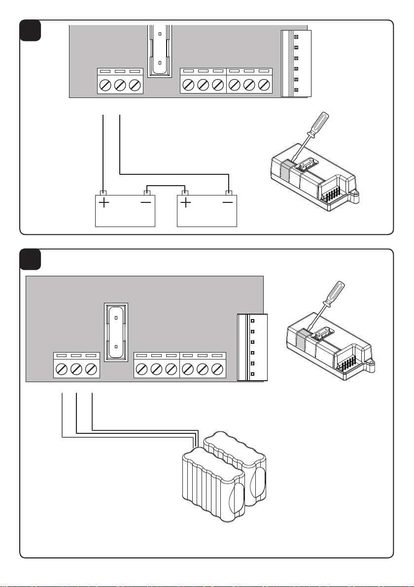
- Conexión de las baterías de plomo mod. DA.BT2/DA.BT6
En la figura 1 se muestra la conexión de las baterías de plomo de 12V. El terminal NTC no se tiene que conectar.
- Conexión de las baterías NiMh
En la figura 2 se muestra la conexión de las baterías de NiMh de 24V.
IMPORTANTE: Es necesario cortar el conector rápido de las baterías de NiMh, para evitar cortocircuitos, córtense
los hilos uno por uno.
Cabe conectar los tres hilos respetando los colores:
Rojo:+ / Negro:- / Azul: NTC (sensor térmico).
Para la conexión con la central de control hay tres modalidades diferentes según el tipo de central:
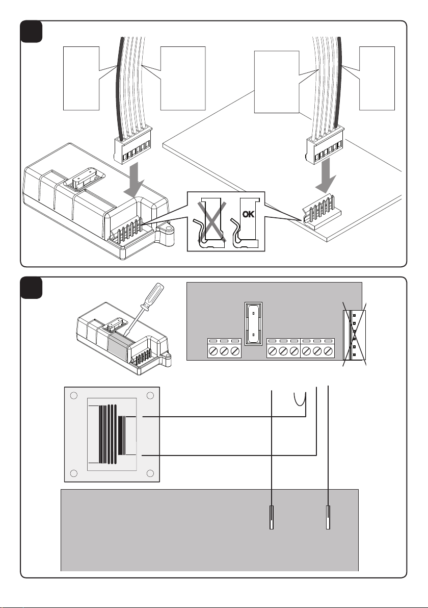
- Central con conector rápido para cargador de baterías:
Si la central tiene conector rápido para el cargador de baterías, basta conectar con el cable suministrado los dos conectores tal y como mostrado en
la Figura 3.
NOTA: Algunas centrales tienen conectores rápidos para otras utilizaciones, por ejemplo para receptores radio.
Compruebe en el manual entregado con la central la presencia efectiva del conector rápido para cargador de baterías, antes de proceder a efectuar
el cableado.
- Central con entradas 0V/24V:
Si la central está conectada al transformador por medio de solamente dos conexiones (0V/24V), desconecte el transformador y, después de haber quitado la
cubierta del borne, realice los cableados destacados en la Figura 4. Es necesario realizar un puente entre los bornes VMTRS y 24 TRS.
- Central con entradas 0V/24V y entrada de velocidad del motor:
Algunas centrales de 24V tienen una conexión adicional que ajusta la velocidad del motor en diferentes valores disponibles en el transformador.
En tal caso desconecte el transformador y, después de haber quitado la cubierta del borne, realice los cableados mostrados en la Figura 5.
En la tabla siguiente se describe detalladamente la regleta.
¡ATENCIÓN!
Durante el funcionamiento al faltar la red general, la salida de accesorios de 24Vac de la central resulta estar polarizada.
Es indispensable comprobar que sea correcta la conexión de los accesorios, como indicado en el manual de
instrucciones de la central de control.
Funciones Entradas/Salidas Características Técnicas:
+ + 24Vdc desde la batería de emergencia Intensidad de carga 200mA
- - 24Vdc desde la batería de emergencia Tensión de carga 27,2 Vdc
NTC Sensor Térmico (sólo para baterías NiMh) Tiempo de carga
(para baterías de 2Ah) 10 horas aproximadamente
0sc Conectar con el conector 0V de la central
0trs Conectar con el secundario 0V del transformador
24trs Conectar con el secundario 24V del transformador (de 23
a 28Vac).
VMtrs
Conectar con el secundario del transformador (min. 23V).
¡ATENCIÓN!: Selecciona la velocidad de funcionamiento
del motor. Hágase referencia a las instrucciones de la cen-
tral de control para conocer la conexión correcta.
VMsc Conectar con el conector VMot de la central
24sc Conectar con el conector VAux de la central
Diagnóstico
En la unidad de control son dos LEDs que indican el estado del sistema:
ESTADO DE LA BATERÍA CARGADOR LED VERDE LED ROJO
Funcionamiento normal - la batería no se carga parpadeo continuo apagado
Carga de la batería en en
Funcionamiento con batería parpadeo rápido apagado
Funzionamento a batteria (con batteria scarica e carico scollegato) 1 Lampeggio breve con pausa 1 Lampeggio breve con pausa
Verifica batteria scollegata parpadeo rápido parpadeo rápido
Batteria NiMh in protezione termica en parpadeo rápido
Notas
Durante el funcionamiento normal con la alimentación de red, la tarjeta se encarga de mantener la carga de las baterías.
En caso de falta de la red eléctrica general, la tarjeta proporciona alimentación a través de las baterías. Un fusible F10A protege la central durante
el funcionamiento con batería de emergencia.
La batería tampón funciona hasta que, descargándose paulatinamente, alcanza el valor de 18V. Al alcanzar dicho valor la batería es desconectada.

CBY.24V POLSKI
Karta do ładowania baterii awaryjnych do centralek sterowania silników 24Vdc.
Można użyć zarówno baterii ołowiowych jak i baterii typu NiMh:
- Podłączenie baterii ołowiowych mod. DA.BT2/DA.BT6
Na rysunku 1 przedstawiono podłączenie baterii ołowiowych 12V. Przewód NTC nie powinien być podłączony.
- Podłączenie baterii NiMh
Na rysunku 2 przedstawiono podłączenie baterii NiMh 24V.
UWAGA WAŻNE: Należy uciąć szybki łącznik baterii NiMh, aby zapobiec krótkim spięciom, uciąć każdorazowo po jednym
drucie.
Podłączyć trzy druty przestrzegając kolorów:
Czerwony:+ / Czarny:- / Niebieski:NTC (czujnik termiczny).
W zależności od rodzaju centralki są dostępne 3 typy podłączenia:
- Centralka z szybkim łącznikiem do ładowarki:
Jeżeli centralka jest wyposażona w szybki łącznik do ładowarki, wystarczy podłączyć dostarczony kabel z dwoma łącznikami, jak przedstawiono na Rysunku
3.
N.B.: Niektóre centralki są wyposażone w szybkie łączniki do innych celów, na przykład do podłączenia odbiorników radiowych.
Przed przystąpieniem do podłączenia kabli, sprawdzić w instrukcji centralki, czy jest obecny szybki łącznik do ładowarki.
- Centralka z wejściami 0V/24V:
Jeżeli centralka jest podłączony do transformatora tylko za pośrednictwem dwóch połączeń (0V/24V), odłączyć transformator i, po usunięciu pokrywki
zacisku, podłączyć kable, jak przedstawiono na Rysunku 4. Należy wykonać mostek między zaciskami VMTRS i 24 TRS.
- Centralka z wejściami 0V/24V i wejściem prędkości silnika:
Niektóre centralki 24V są wyposażone w dodatkowe połączenie do regulacji prędkości silnika wg różnych wartości dostępnych w transformatorze.
W tym przypadku należy odłączyć transformator i, po zdjęciu pokrywki zacisku, podłączyć kable, jak przedstawiono na Rysunku 5.
W poniższej tabeli podano szczegóły dotyczące listwy zaciskowej. UWAGA!
Podczas funkcjonowania bez sieci, wyjście osprzętu 24Vac centralki jest spolaryzowane.
Należy sprawdzić poprawność podłączenia osprzętu, jak opisano w instrukcji obsługi centralki sterowniczej.
Funkcje wejść/wyjść Dane techniczne:
+ + 24Vdc od baterii awaryjnej Prąd ładowania 200mA
- - 24Vdc od baterii awaryjnej Napięcie ładowania 27,2 Vdc
NTC Czujnik termiczny (dotyczy tylko baterii NiMh) Czas ładowania
(baterie 2Ah) Około 10 godzin
0sc Podłączyć do łącznika 0V centralki
0trs Podłączyć do wtórnego wejścia 0V transformatora
24trs Podłączyć do wtórnego wejścia 24V transformatora (od 23
do 28Vac)
VMtrs
Podłączyć do wtórnego wejścia transformatora (min. 23V)
UWAGA!: Zaznaczyć prędkość funkcjonowania silnika.
Skonsultować instrukcje centralki sterowniczej odnośnie
prawidłowego podłączenia.
VMsc Podłączyć do łącznika VMot centralki
24sc Podłączyć do łącznika VAux centralki
Diagnostyka
W centrali są dwie diody LED, które wskazują stan systemu:
STAN ŁADOWARKA zielona dioda LED czerwona dioda LED
Normalna praca - bateria nie ładuje ciągłe miganie z
Łado wanie baterii na na
Praca na zasilaniu bateryjnym szybkie miganie z
Pracy z baterii (z odłączonym akumulatorem i obciążeniem) Miga z 1 krótkiej przerwie Miga z 1 krótkiej przerwie
Sprawdź akumulator odłączony szybkie miganie szybkie miganie
NiMh w zabezpieczenie termiczne na szybkie miganie
Uwagi
Podczas normalnego funkcjonowania przy zasilaniu sieciowym, karta utrzymuje stan naładowania baterii.
W razie braku zasilania sieciowego, karta dostarcza zasilanie za pośrednictwem baterii. Bezpiecznik F10A chroni centralkę podczas zasilania baterią
awaryjną.
Bateria buforowa funkcjonuje do chwili, gdy po stopniowym rozładowaniu, osiągnie wartość 18V. Po osiągnięciu tej wartości, bateria jest odłączana.
10


AUTOMATISMI BENINCÀ SpA - Via Capitello, 45 - 36066 Sandrigo (VI) -Tel. 0444 751030 r.a. - Fax 0444 759728
Table of contents
Languages: