Bennett Marine AutoTrimPro Operation manual

IMPORTANT SAFETY INSTRUCTIONS: Read and follow all instructions. Keep this manual on your boat.
Installation & User's Guide For Electric Trim Tab Systems
All-in-one trim tab control system

Congrats!
Behind You For The Distance
Bennett’s legendary customer service and support is a priceless perk to your
new purchase! Our expert staff with over 50 years of trim tab experience is
ready to assist with your installation, help with troubleshooting, or answer any
of your questions along the way.
How to Contact Us
Call us at 1-954-427-1400, email Info@BennettTrimTabs.com, or go to
BennettTrimTabs.com/Contact and ll out the online form. Please allow 24
hours for online requests. Our ofce hours are Monday through Friday from
8:00 a.m. to 5:00 p.m. (Eastern Standard Time).
The Benefits of Trim Tabs
Increase Visibility For A Safer Ride: Keeping your bow down at reduced
speeds is important, especially in congested waters or foul weather. Bennett
trim tabs enable you to plane at a much lower speed, operating your boat more
safely.
Save Money With Better Fuel Efciency: Getting up on plane quicker means
your boat spends less time running inefciently. Bennett trim tabs decrease
engine laboring, dramatically improving your fuel economy and prolonging the
life of the engine.
Maximize Performance While Smoothing Out The Ride: Bennett trim tabs
enhance the operating economy of your boat by lifting the stern in proportion to
speed, weight distribution, and fuel load changes.
2Bennett Marine | AutoTrim Pro Trim Tab Control System
Congratulations on your purchase! We're proud to say, boaters trust
our brand. After all, we invented the world’s rst adjustable trim
tab—and never stopped pushing forward, always striving to make a
better, more affordable system with maximum performance.

Contents
Contacting Us .................................................................................. 2
System Overview
System Overview............................................................................................... 4
System Components .......................................................................................... 5
Planning and Installation
Planning the Installation .................................................................................... 6
Installation of System Components ................................................................. 8
ATP Helm Display Drilling Templates ............................................................ 11
System Wiring Diagram ................................................................................... 13
System Set-up
Angle Calibration............................................................................................... 14
Auto Mode Set-up (Favorite Buttons) ............................................................... 16
Trim Tab Basics
How Trim Tabs Work......................................................................................... 20
Special Conditions & Safety ............................................................................ 22
AutoTrim Pro Operation
ATP Helm Display Quickstart Guide................................................................. 24
Indication & Manual Mode Buttons ................................................................. 25
Semi-Automatic Controls ................................................................................ 27
Using Automatic Modes .................................................................................. 29
Understanding Automatic Operation ............................................................... 31
Troubleshooting
.................................................................................. 36
Warranty
.................................................................................................... 45
System Overview
The Bennett ATP control is designed to enhance the boating experience
by taking control of the trim tab operations during the time that the user is
operating the boat.
Proper installation of the system components is critical for safe and optimal
operation of the system. The electric ATP control works with all standard
Bennett Marine trim electric tab systems and many other electric trim tab
systems. The ATP is a complete control system and does not require any
other user interface. Manual control, automatic control, trim tab position
indication, and automatic trim tab retraction features are all integrated into
the ATP system's Helm Display.
The ATP control is the “brains” of the system. The ATP control will
constantly measure and monitor the boat's pitch and roll attitude, then
operate the trim tab actuators. Because the ATP is truly a control, the ATP can
be combined with the appropriate power switching device and can control
many commercially available electric trim tab systems, thus adding a high
degree of usability to any system.
All-in-one trim tab control system
AutoTrim Pro
4Bennett Marine | AutoTrim Pro Trim Tab Control System
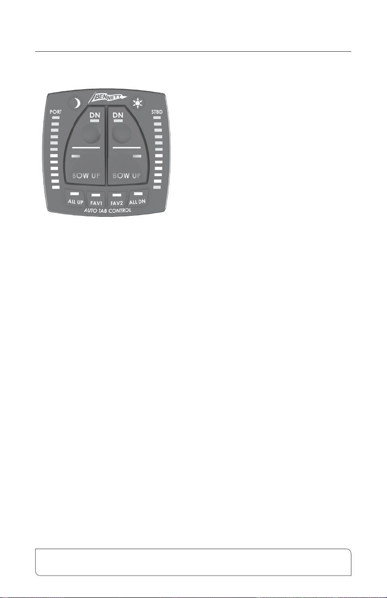
System Components
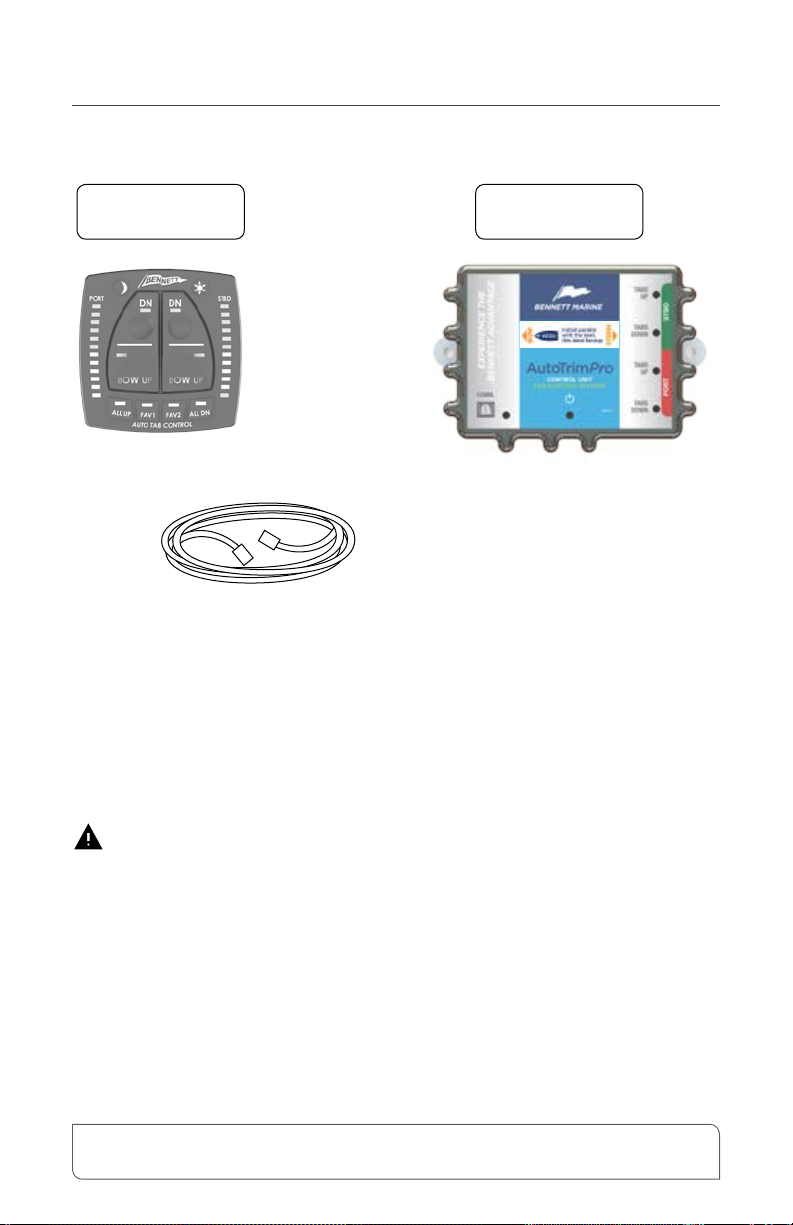
The AutoTrim Pro (ATP) is an all-in-one trim tab control system consisting of
two components, the Helm Display and the Control Unit.
Please refer to the system diagram on page 13 for detailed system wiring requirements.
For detailed information on actuators, trim tabs, and other components, please refer to
the trim tab information that was provided with your trim tabs, or visit BennettTrimTabs.
com/Installation.
Is your system already installed? Please skip to page 24 to learn how to
use your AutoTrim Pro. Enjoy the Ride!
Bennett Marine | AutoTrim Pro Trim Tab Control System 5
AutoTrim Pro
Helm Display
AutoTrim Pro
Control Unit
AutoTrim
Pro Kit Part#:
AP000A1BC
25' Helm Display
Extension
Getting Started
Installation of the ATP control
system will assume that the
installation of the trim tabs,
actuators, and wiring has been
completed according to the
corresponding trim tab
installation and users guides which
can be downloaded at
BennettTrimTabs.com/Installation.
The ATP control system contains the
following basic items.
1. ATP Helm Display
2. ATP Control Unit
3. Hardware and Cables
Additional components may be required
for more complex systems. Please call
Bennett Marine at (954) 427-1400 with
any questions.
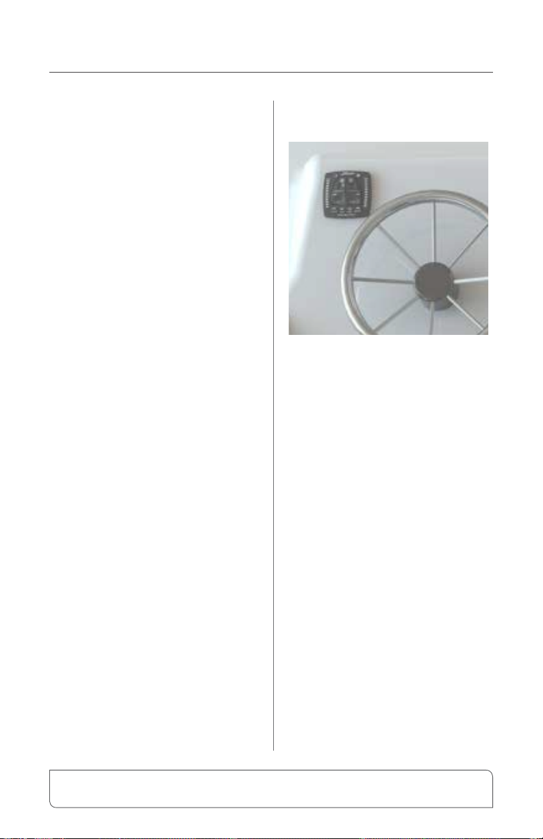
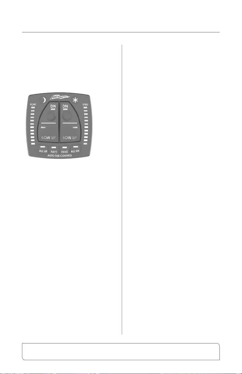
ATP Helm Display
Locate an appropriate location on
the helm for the ATP Helm Display.
The ATP Helm Display should be
installed such that the vessel operator
has a clear, unobstructed view of
the display, and is easily reachable
from the operating position. Ideally,
the ATP Helm Display should be
installed in a horizontal position.
This makes the use of the control
more intuitive. It is important for the
vessel operator to be able to clearly
see the LED indicators on the ATP
Helm Display to know what the ATP
is doing. Before installing the ATP
Helm Display, check for obstructions
on the underside of the helm.
See page 8 for detailed installation
instructions.
Planning The Installation
6Bennett Marine | AutoTrim Pro Trim Tab Control System
continued Planning The Installation
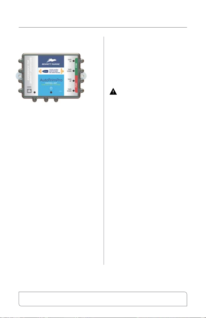
ATP Control Unit
e ATP control unit must be
mounted horizontally and parallel
with the keel of the boat. e label
indicates with an arrow which end
should be oriented towards the bow
of the boat. e location of the ATP
control unit within the boat is not
critical, but the orientation of the
ATP control unit to the boat is very
important.
The ATP Control Unit should be
mounted on a rigid structure in the
boat, and should not be mounted
within 24" of any magnetic items
such as electric motors or speakers.
See page 9 for detailed installation
instructions.
The Bennett AutoTrim Pro
is not backwards compatible to
existing control systems, meaning
the ATP control system replaces all
BOLT Rocker Switch controls and
all Indicator Controls.
Bennett Marine | AutoTrim Pro Trim Tab Control System 7
Before starting any work, disconnect
the battery(s), and verify that all
power is turned off.
ATP Helm Display
1. Use the template included on
Page 11 to help decide the
location for the ATP Helm
Display. The Helm Display
should be located on the helm in
view of the operator, and within
easy reach. It is important for
the vessel operator to be able to
clearly see the LED indicators on
the ATP Helm Display to know
what the ATP is doing. Before
installing the ATP Helm Display,
check for obstructions on the
underside of the helm.
2. Drill the center hole 1" using the
template from page 11
3. Drill the four screw holes 3/16"
4. Thread the wires for the ATP
Helm Display through the 1" hole
5. Secure the ATP Helm Display
using the four 8-32 nylon thumb
nuts included.
6. Locate the power source for all
of the helm instrumentation.
Connect the orange wire from the
ATP Helm Display to the power
source for the instrumentation.
When power is removed from the
orange wire, the system will shut
down.
7. Locate the ignition
power. Consult the engine
manufacturer’s documentation
to identify a source for ignition
power. Connect the purple wire
from the ATP display to the
ignition power. The ATP Helm
Display does not use any power
from the ignition system, but
senses when the power to the
ignition has been turned off to
automatically raise the trim tabs.
Note: The orange and purple
wire cannot be connected to the
same source. If the orange wire
is connected to the ignition, the
auto tab retract feature will not
function.
8. Locate a suitable ground.
Connect the black wire from the
ATP Helm Display to the ground
source for the instrumentation.
If a second helm station is utilized in
this system, repeat steps 1-5 only for
the upper station ATP Helm Display.
8Bennett Marine | AutoTrim Pro Trim Tab Control System
Installation of System Components

Installation of System Components
ATP Control Unit
The ATP Control Unit is the sensor
and processor for the ATP system.
The ATP Control Unit contains
an accelerometer, gyroscope, and
an electronic compass that sense
the position of the boat, and the
accelerations and decelerations
that the boat is moving through.
The ATP Control Unit must be
properly oriented on the boat to
correctly interpret acceleration and
deceleration.
1. Locate a suitable dry location for
the ATP Control Unit.
2. Position the control unit such that
the arrow label on the Control Unit
is parallel to the keel of the boat
and pointed towards the bow. e
the above graphic. e direction
of installation is important so that
the internal accelerometer and
gyroscope are oriented properly
with the vessel. If a suitable size at
surface cannot be located, Bennett
Marine oers a vertical mounting
bracket that will provide the at
surface.
3. Mount the Control Unit using the
two #8 x ½" screws provided.
4. Connect the orange and black
power wires to a power source
capable of supplying 20 Amps @
12V or 10 Amps at 24V. (Refer to
systems diagrams beginning on
page 13)
Connecting the system
1. Connect the communications cable
from the ATP Helm Display to the
communications cable on the ATP
Control Unit.
2. Connect the port actuator cable to
the blue and yellow cable (with the
red tag) on the ATP Control Unit.
3. Connect the stbd. actuator cable
to the blue and yellow cable (with
the green band) on the ATP Control
Unit.
Testing the system
1. Reconnect the battery(s) or turn the
battery switch to ON.
2. Turn the ignition to the ON
position.
3. The ATP Helm Display should
illuminate
Continued on page 10
Bennett Marine | AutoTrim Pro Trim Tab Control System 9

Installation of System Components
4. The two blue LEDs over FAV1
and FAV2 should be ashing.
This is an indication that the
system has not been oriented to
the boat.
5. Press the PORT Bow DN button
on the ATP Helm Display. The
Starboard actuator should
extend. If the Starboard
actuator does not extend, or the
PORT actuator extends instead
of the Starboard actuator, refer
to the troubleshooting section.
6. Press the STBD Bow DN button
on the ATP Helm Display. The
PORT actuator should extend. If
the PORT actuator does not
extend, or the STBD actuator
extends instead of the PORT
actuator, refer to the
troubleshooting section.
10 Bennett Marine | AutoTrim Pro Trim Tab Control System
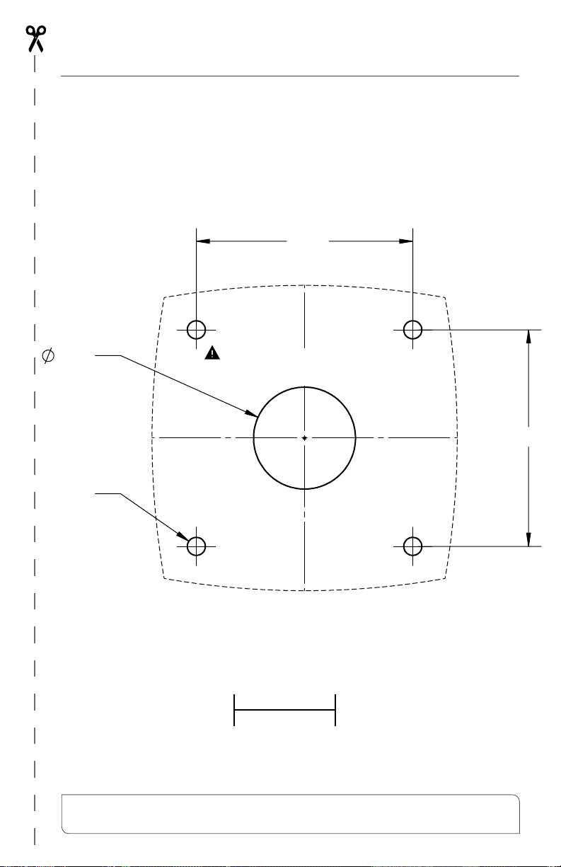
2.13
2.13
1"
1.00
3/16"
ATP Helm Display Drilling Template
Verify template dimensions if
printed from the web or copied
Must be printed or
copied at 100% scale
1"
Bennett Marine | AutoTrim Pro Trim Tab Control System 11

12 Bennett Marine | AutoTrim Pro Trim Tab Control System

System Wiring Diagram
Please call us at (954) 427-1400 for
additional help with wiring instructions
ORANGE WIRE
CONNECT TO HELM POWER
ORANGE WIRE
CONNECT TO
20A (12V)
10A (24V)
GROUND
PURPLE WIRE
CONNECT TO IGNITION
GROUND
3
4
65
1 2
No.
PART NAME
DESCRIPTION
1
BQEACT-XX
Actuators
2
BQEMTREXTCABLE-X
PORT SIDE Extension Cable
3
BQEMTREXTCABLE-X
STBD SIDE Extension Cable
4
BQEDISEXTCABLE-X
ATPCTRLUNIT Extension Cable
5
ATPCTRLUNIT
ATP Control Unit
6
JUNBOX2-1-1 / JUNBOX1-1-1
Junction BOx
7
BQEDISEXTCABLE-X
Relay Module Extension Cable
8
BQERM-XX
Relay Module
9
ATPDISPLAY
Display
10
BQEDISEXTCABLE-X
Display Extension Cable
11
BQEDISEXTCABLE-X
Bridge Display Extension Cable
12
ATPDISPLAY
Bridge Display
D
C
B
A
A
B
C
D
1
2
3
4
5
6
7
8
8
7
6
5
4
3
2
1
THE INFORMATION CONTAINED IN THIS
DRAWING IS THE SOLE PROPERTY OF
Bennett Marine Inc. ANY REPRODUCTION
IN PART OR AS A WHOLE WITHOUT THE
WRITTEN PERMISSION OF
Bennett Marine Inc IS PROHIBITED.
PROPRIETARY AND CONFIDENTIAL
DIMENSIONS ARE IN INCHES
TOLERANCES:
FRACTIONAL
1/16
ANGULAR: MACH
BEND
TWO PLACE DECIMAL
.01
THREE PLACE DECIMAL
.005
INTERPRET GEOMETRIC
TOLERANCING PER: ANSI Y-14
DRAWN
DATE
NAME
TITLE:
SIZE
B
DWG. NO.
REV
WEIGHT:
SCALE: 1:12
UNLESS OTHERWISE SPECIFIED:
Single BQE with ATP
SHEET 1 OF 1
DO NOT SCALE DRAWING
Bennett Marine
550 Jim Moran Blvd
Deerfield Beach, FL 33442
1. Port Actuator
2. Starboard Actuator
3. *Actuator Extension Cables
4. Control Unit
5. ATP Display
6. Display Extension Cable
*Optional
Single Helm Display,
Single Actuators
Bennett Marine | AutoTrim Pro Trim Tab Control System 13
This diagram also works with
Lenco Marine actuators

These steps cannot be completed
until the boat is launched
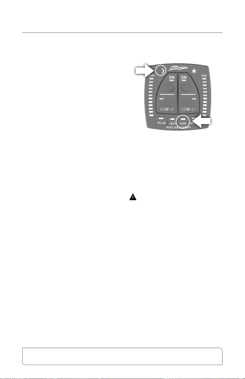
Angle Set-up
The ATP system will evaluate the
vessel's pitch angle to determine the
mode the boat is operating in. In order
to properly measure the pitch and roll
attitude of the boat, the ATP Control
Unit must be oriented to the boat.
1. Orient the system to the boat.
• Launch the boat.
• Turn the system on.
• Allow the boat to come to a rest.
• Press and hold the Moon and
ALL UP buttons for three
seconds.
This will set the resting position of
the boat and allow the system to
retract the trim tabs any time that the
system detects the boat is at rest.
The system will ash all four corner
LEDs to indicate that a setting has
been made.
2. Idle Angle Set-up
The idle angle is used to determine
that the vessel is in a slow moving
state. Trim tabs should be fully
retracted any time the vessel is
moving at idle speed as trim tabs
will have no effect without water
pressure against them. The idle
angle should be set in calm water
with the trim tabs fully retracted,
and the vessel idling at a fast idle
speed, usually about 1500rpm-
2000rpm. The boat should be
throwing the largest wake that would
be acceptable in a NO WAKE zone.
To set the idle angle, get the boat
moving at an appropriate idle speed,
run the boat at this speed for 10-15
seconds to allow the boat to settle.
After settling, press and hold the
moon button and the FAV1 button at
the same time for at least 5 seconds.
During the time the buttons are being
held, the system is continuously
taking measurements. The system
will use the average of all the
measurements that were taken while
System Set-up
14 Bennett Marine | AutoTrim Pro Trim Tab Control System
System Set Up continued
both buttons are held. The system
will ash all four corner LEDs to
indicate that a setting has been made.
3. Planing Angle Set-up
The planing angle is used to
determine that the vessel is on plane.
The trim tabs will be deployed to
varying degrees while the boat is
planing to improve the boat's attitude
in roll and pitch. The planing angle
is not the target position that the
boat will be maintained at, rather it
is an identier to tell the system that
the boat is in the planing mode. If
the boat's pitch angle drops below
the planing angle, the system will
automatically retract the tabs. If
the boat's pitch angle is above
the planing angle, the system will
automatically control the trim tabs.
The planing angle should be set in
relatively calm water.
Put the trim tabs to a full-down
position and carefully run the boat at
it’s fastest safe speed to set the
planing angle. When the boat has
settled into a steady pitch position
and a steady speed, press and hold
the Moon and FAV2 buttons for 5
seconds. Allow another 15 seconds to
let the system settle. This will set the
planing angle.
The system will ash all four corner
LEDs to indicate that a setting has
been made.
Caution: The boat may be
temporarily very over-trimmed in
this attitude and have a potential to
bow steer during the set-up only.
This is not the target position, but
rather the limits of the operation
range of the trim tabs.
Bennett Marine | AutoTrim Pro Trim Tab Control System 15
System Set Up: Angle Set-up continued
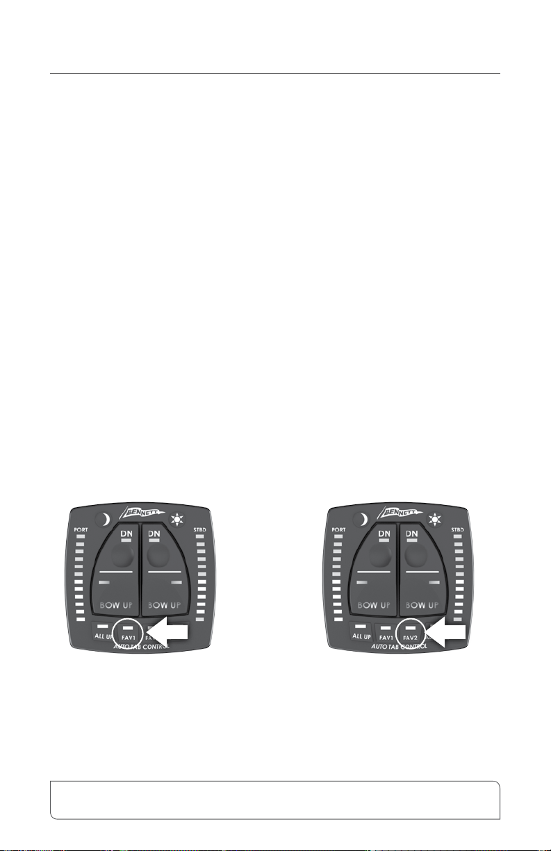
Favorite Position Set-up
The FAV1 and FAV2 buttons on
the control are stored pitch and roll
positions that the system will try
to maintain the boat at the stored
positions by adjusting the trim tabs
accordingly. To set a favorite position,
use the manual trim tab controls (and
any other preferred means such as
engine tilt or throttle controls) to get
the boat into the attitude that you want
the boat to run at.
Press and hold the FAV1 or FAV2
button for 5 seconds. During
the time that the FAV1 or FAV2
buttons are being held, the system
will constantly take pitch and roll
measurements. When the FAV1 or
FAV2 button is released, the system
will store the average pitch and
roll positions that were measured
while the FAV button was held.
The system will immediately begin
automatic control and try to maintain
the vessel at the stored position by
adjusting the trim tabs.
To activate either FAV setting,
simply tap either button as desired.
For more information, see the
"Using Automatic Operating Modes"
section on page 29.
Favorite 1 Favorite 2
16 Bennett Marine | AutoTrim Pro Trim Tab Control System

System Set Up: Auto Mode (Favorites) Set-up
Bennett Marine | AutoTrim Pro Trim Tab Control System 17

Trim Tab
Basics
Trim Tab Basics
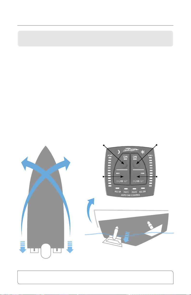
Figure 1
Bennett trim tabs most often attach to the bottom edge of the transom (although
other mounting variations are available). When the Helm Display is pressed,
the trim tabs move into position. Water-force on the trim tab creates upward
pressure, raising the stern and lowering the bow. Properly sized trim tabs improve
the performance of your boat in a wide range of weight, weather and water
conditions.
In general, trim tabs operate in reverse of what you may think (Figure 1). The
port (left) trim tab controls the starboard (right) bow. Conversely, the starboard
(right) trim tab controls the port (left) bow. When operating your trim tabs
manually, the Helm Display is wired so that all you have to do is press the control
in the direction you want the bow to move. Don’t worry about which trim tab
is moving. The proper use of Bennett Trim Tabs becomes second nature after a
short time. For information about operating ATP auto mode, see page 24.
Port
Tab
Port Bow Stbd.Bow
Stbd.
Tab
Pitch Correction
Stbd.
Tab
When the port tab is lowered individually, an upward
force at the port stern of the boat is created. The
inverse applies when lowering the stbd. tab individually.
Roll Correction
Port
Tab
Lowers
Starboard
Bow
Raises
Starboard
Bow
Lowers
Port
Bow
Raises
Port
Bow
20 Bennett Marine | AutoTrim Pro Trim Tab Control System
This section is intended to provide a general overview of how trim tabs work.
For detailed information on operating your AutoTrim Pro, see page 24.
Other manuals for AutoTrimPro
4
Table of contents
Other Bennett Marine Boating Equipment manuals


Popular Boating Equipment manuals by other brands


Humphree
Humphree HCS-5 installation manual

Vetus
Vetus BOW4512D Operation manual and installation instructions

Dock Doctors
Dock Doctors SLIDING BOARDING STEP Assembly instructions

Mastervolt
Mastervolt Mass Combi 12/2000-100 Quick installation

SeaView
SeaView PM5-FMD-8 installation instructions

Hobie
Hobie Mirage 360 manual


