Benning Tebevert 500 User manual

OPERATIONS AND
MAINTENANCE MANUAL
For
Benning Power Electronics
SLIMLINE INVERTER
24VDC @ 500VA
48VDC @ 1000VA
(028-0009-004 Rev B)
SAVE THESE IMPORTANT
SAFETY INSTRUCTIONS
This manual contains important safety instruc-
tions that should be followed during installation
and maintenance of the Power System.
11120 Grader Street
Dallas, TX 75238
214-553-1444, Fax 214-553-1355


Document No. 062-005
Preface
Congratulations and thank you for purchasing a Benning BLI Modular Inverter System.
We at Benning are committed to supporting the needs of our customers by supplying the customer
with the proper information and documentation needed to properly install and operate the Inverter
System purchased.
Important:
It is imperative that all the information be observed.
This avoids:
9Danger during installation and operation.
9Danger to operating personnel.
9Downtime.
9Increases the reliability and lifespan of the system.
These manuals explain all the necessary information to unpack, install, and operate the BLI25000
Modular Inverter System and related components. Refer questions outside the scope of this manual
to our Customer Service Department.
Customer Service:
We are committed to excellence in dependability and customer satisfaction. If you have any
questions or problems, please contact the Customer Service Department at: 1-800-910-3601 or 214-
553-1444 for more information.
Please read all instructions before installing or operating the equipment and save these manuals for
future reference.


Operating Instructions
Date Designation No. 4219en R2
Issued: August 8, 2005 DTL Page 1/22pages
Revision
Checked
Switch mode, single-phase, sine-wave Inverter
Product line TEBEVERT
Series
TEBEVERT 500 and TEBEVERT 1000
(19”/3.5”, with mechanical transfer relay, DSP technology)

Switch mode, single-phase, sine-wave Inverter
Product line TEBEVERT
August 8, 2005 - DTL 2/21 No. 4219en R2
Page left blank intentionally

Switch mode, single-phase, sine-wave Inverter
Product line TEBEVERT
August 8, 2005 - DTL 3/21 No. 4219en R2
Table of contents
1
Safety notes ............................................................................................... 6
2
General ...................................................................................................... 7
3
Inverter ...................................................................................................... 8
3.1
Design of the unit ...................................................................................... 9
3.2
Terminals and operating elements .......................................................... 10
3.3
Technical data ......................................................................................... 12
4
Assembly and commissioning ................................................................ 16
4.1
Device settings ........................................................................................ 16
4.2
Connecting the inverter ........................................................................... 16
4.3
Installation of the unit ............................................................................. 18
4.4
Commissioning the inverter .................................................................... 18
5
Maintenance / repair................................................................................ 19
6
Description of function ........................................................................... 20
7
Appendix ................................................................................................. 21

Switch mode, single-phase, sine-wave Inverter
Product line TEBEVERT
August 8, 2005 - DTL 4/21 No. 4219en R2
These operating instructions contain important information for
the installation, operation and maintenance of the inverter. The
instructions must be retained and observed at all times!
This avoids
•Danger during operation
•Danger to the operator
•Downtime
•Enhances the reliability and life span of the inverter.
Service Centre
For reasons of operational safety and operational availability we recommend to
regularly maintain the units and systems.
For more detailed information call our service centre under phone
+1 214 553 1444
In addition, our helpdesk team is 24 hours per day at your disposal for technical
support under phone +1 800 910 3601
BENNING Power Electronics, Inc.
11120 Grader St.
Dallas, TX 75238
214-553-1444
www.benning.us
Switch mode, single-phase, sine-wave Inverter
Product line TEBEVERT
August 8, 2005 - DTL 5/21 No. 4219en R2
Explanation of the symbols used:
Indicates safety instructions which must be followed to avoid
danger to persons!
Indicates instructions which must be followed to avoid material
damage!
All specifications in these operating instructions must be observed
at all times!
ព
ពព
ព
General instructions which must be observed
Further symbols and pictograms are explained at the appropriate places in the
operating instructions.

Switch mode, single-phase, sine-wave Inverter
Product line TEBEVERT
August 8, 2005 - DTL 6/21 No. 4219en R2
1 Safety notes
The inverter is an electronic device which operates at dangerous
voltage and current levels.
For this reason, the following instructions must be followed at all times!
1. The inverter should be installed, operated, repaired and maintained in
accordance with the instructions in this document.
2. Only fully trained and qualified personnel should have access to the
system. Only qualified and authorized personnel should be able to install
the units.
3. Even when the inverter is switched off, some of its interior components
remain live as long as it is connected to the commercial AC bypass supply
or the battery.
4. Capacitors may be charged even when the unit is disconnected. These
must be correctly discharged by a qualified electrician before the
connections or terminals are touched.
5. When working with the unit, use properly insulated tools at all times
which are suitable for the levels of voltage concerned.
6. All persons working with the unit must be familiar with the first-aid
measures to be adopted in cases of accidents involving electricity.
7. Always observe the regulations of the local operating company as well as
other safety regulations.
Attention!
The inverter may be operated only on 120 VAC (L1, N, G)
systems.
The neutral conductor of the inverter is connected internally to the
protective wire. ( )
Switch-over from inverter to commercial AC bypass or from
commercial AC bypass to inverter always takes place with both
the L1 and N poles!

Switch mode, single-phase, sine-wave Inverter
Product line TEBEVERT
August 8, 2005 - DTL 7/21 No. 4219en R2
2 General
The inverters in the product line TEBEVERT with an integrated switch-over
device can be utilized for a wide range of applications in the field of
telecommunications and other applications.
The output power of the inverter is either 500VA with 24VDC input models or
1000VA with 48VDC input models.
The inverters utilize Digital Signal Processor (DSP) technology, programmed with
the appropriate algorithms to carry out control and monitoring of the inverter.
Attention!
These inverters are not designed for parallel operation!

Switch mode, single-phase, sine-wave Inverter
Product line TEBEVERT
August 8, 2005 - DTL 8/21 No. 4219en R2
3 Inverter
The DC input voltage of 24VDC or 48VDC (depending on the model) is converted
inside the inverter to an AC voltage of 120VAC and 60Hz.
Fig. 1: Inverter outline
Switch mode, single-phase, sine-wave Inverter
Product line TEBEVERT
August 8, 2005 - DTL 9/21 No. 4219en R2
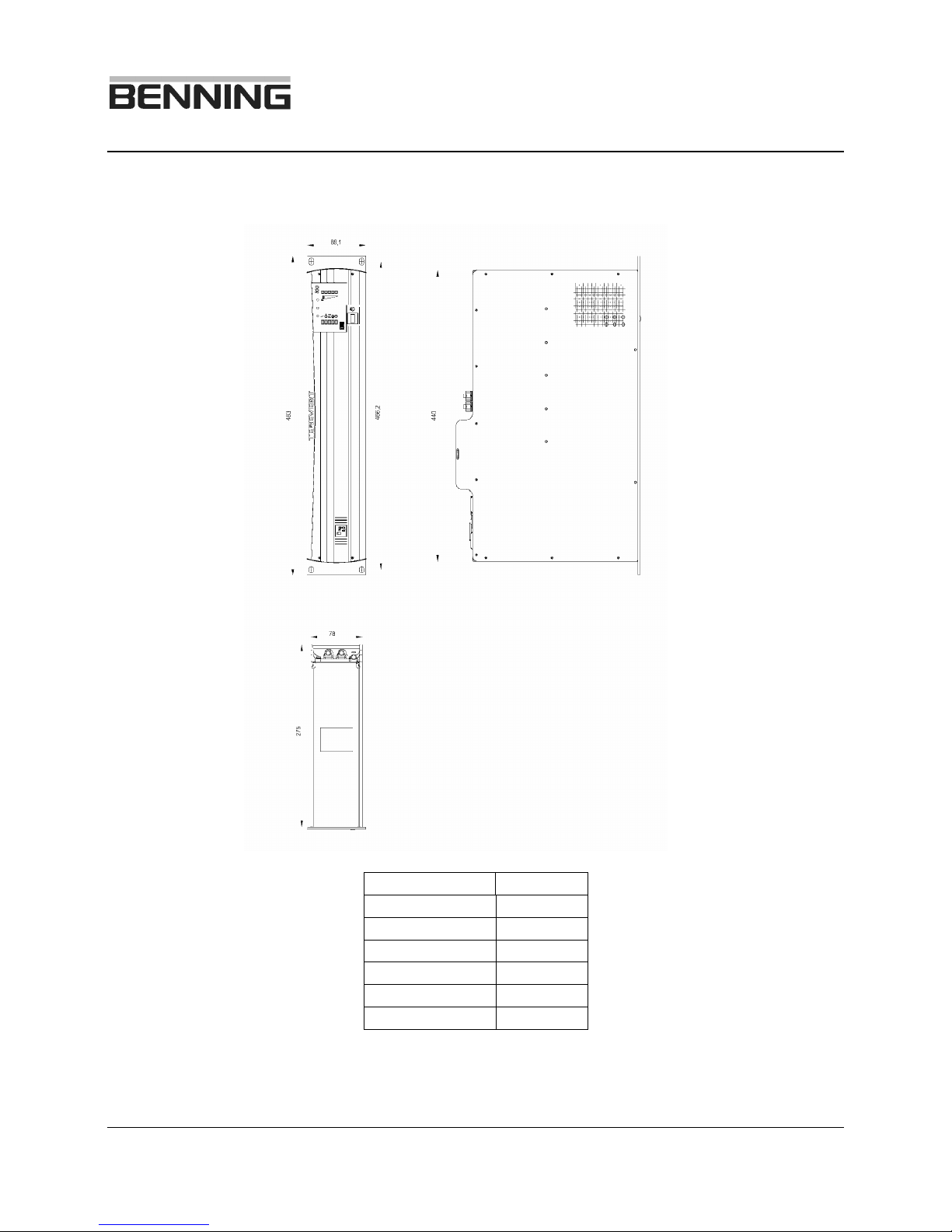
3.1 Dimensions of the unit
Millimeter Inches
78 3.07”
275 10.82”
483 19”
466.2 18.35”
440 17.32”
88.1 3.47”
Fig. 2: Dimension diagram of the inverter

Switch mode, single-phase, sine-wave Inverter
Product line TEBEVERT
August 8, 2005 - DTL 10/21 No. 4219en R2
3.2 Terminals and operating elements
All operating elements are located on the front, installer connections are found on
the rear the inverter.
Fig. 3: Front view of the inverter TEBEVERT 500
1Unit switch ON/OFF
The inverter can be switched on and off with this push button switch.
2LED’s for indicating the inverter status
LED Color
Meaning
red Error
green
Output voltage present and connected through to the
load receptacles
green
No function in this application!
green
The DC input voltage is within the acceptable input
range. If light is blinking the DC voltage is out of
range.
green
Inverter ON
1
2
3

Switch mode, single-phase, sine-wave Inverter
Product line TEBEVERT
August 8, 2005 - DTL 11/21 No. 4219en R2
3LED’s for signalling the actual inverter output power
The inverter is overloaded if the LED is flashing
(RED)
When this LED is lit the inverter is loaded nearly to
the limit (YELLOW)
The lit LED’s indicate the approximate load level
(Green)
Fig. 4: Rear view of the inverter
1X1(+); Copper bar / threaded stud; plus (+) connection for the DC input
of the inverter. Arranged for ¼” x 5/8”, two-hole crimp lug
2X3; inverter output receptacle No. 2, 5-15 R. * 12033X-HW1 has a
terminal block for hardwired output in this position.
1
3F1; thermal over current trip circuit breaker
4X4; inverter output receptacle No. 1, 5-15 R
5X2; Commercial AC bypass input IEC-320 (Cord not included)
1
12033X-HW1: 12 AWG cable is the max allowable cable size
P
max
1
2
*
3
4
8
7
6
5

Switch mode, single-phase, sine-wave Inverter
Product line TEBEVERT
August 8, 2005 - DTL 12/21 No. 4219en R2
6X5; potential free central fault signal
X5:1-2 fault
X5:1-3 no fault
7X1(-); Copper bar / threaded stud; negative (-) connection for the DC
input of the inverter. Arranged for ¼” x 5/8”, two-hole crimp lug
8threaded stud; frame ground connection, arranged for ¼” x
5/8”, two-hole crimp lug.
* 12033X-HW1

Switch mode, single-phase, sine-wave Inverter
Product line TEBEVERT
August 8, 2005 - DTL 13/21 No. 4219en R2
3.3 Technical Data
DC input:
DC voltage: 24 VDC (48 VDC)
Permissible deviation from rated value: +20%; -15%
Input current at rated real power
Nominal input voltage 100%: 19.8 A (19.0 A)
Over voltage 120%: 16.3 A (16.0 A)
Under voltage 85%: 22.6 A (22.5 A)
Input current with no load and rated voltage: 1.0 A
Tolerated residual ripple on the input voltage: 5% rms
AC bypass input:
AC voltage: 120 VAC
Frequency: 60 Hz
AC Output:
AC voltage: 120 VAC
Static voltage tolerance: ±1%
(inverter operation)
Rated power (cosϕ=0.8): 0.5 kVA (1.0 kVA)
Rated active power: 0.4 kW (0.8 kVA)
Rated current (cosϕ=0.8): 4.2 A (8.3 A)
Short circuit behavior:
(DIN VDE 0100 - 410) >13A
rms
(>20A
rms
) for 40ms,
then switch-off
Overload behaviour: 2xI
N
for 4 s, then reduction to
1.2xI
N
for 60 s, then switch-off
Permanently tolerated overload: 1.1xI
N

Switch mode, single-phase, sine-wave Inverter
Product line TEBEVERT
August 8, 2005 - DTL 14/21 No. 4219en R2
Crest factor: 2.8; @ 120V/4.2A (@120V/8.3A)
maximum peak current 2.8xI
N
,
with larger crest factor the permissible
rms. current is less
Frequency: 60 Hz (50Hz option)
Frequency stability: ±0.1% inverter operation
Harmonic distortion factor: ≤3% with linear load
Permissible power factor: cosϕ=0.7 ind. to cosϕ=0.8 cap.
Efficiency at rated real power:
>
85 % (> 88 %)
Weight: 13.2 lbs. (6 kg)
Tolerated temperature range
(without condensation): 0°C.... +40°C without reduction
+40°C ... +60°C
Reduction 3.5%P
N
/°C
Automatic High Temp Shut-down: +60°C
Automatic re-start after High Temp
Shut Down: +55°C
Cooling method: temperature controlled forced
ventilation
Contact rating of the potential free
central fault signal: max. 160VAC / 8A
Bypass input CB (internal): 5 A (10 A)
Thermal over current trip CB
Commercial AC bypass input (external): max. 15A (moulded case circuit
breaker)
2
2
The commercial AC bypass input must be protected by a circuit breaker rated for branch
protection (UL489) according to NEC

Switch mode, single-phase, sine-wave Inverter
Product line TEBEVERT
August 8, 2005 - DTL 15/21 No. 4219en R2
Load fuse: The short circuit current can blow
slow fuses with
1
/
3
of the nominal
current rating.
Radio interference degree: Class B (EN 55022)
Switch-over device: Mechanical contactor
Switching times: ≤100 ms
Switching thresholds of the input voltage monitoring:
3
Setting parameter Default settings
Lower switch-off threshold U1 20.4 V
Switch-on threshold U2 24.5 V
Switch-on threshold U3 28.8 V
Upper switch-off threshold U4 30.0 V
Rated input voltage 48 V DC
Lower switch-off threshold U1 40.8 V
Switch-on threshold U2 49.0 V
Switch-on threshold U3 57.6 V
Upper switch-off threshold U4 60.0 V
The inverter can be switched on only when the input voltage UDC ≥U2.
Switch mode, single-phase, sine-wave Inverter
Product line TEBEVERT
August 8, 2005 - DTL 16/21 No. 4219en R2
4 Assembly and commissioning
Attention!
The safety instructions must be observed at all times during
assembly, installation and commissioning!
After installation, connecting and commissioning the inverter is ready for
operation without restriction. No additional settings and readjustments are
necessary during operation under all operating conditions.
The inverter is designed for operation in closed and dry environment. The
maximum permissible ambient temperature is +40°C. without de-rating. The
inverter is designed to operate in a controlled environment. Attention must be paid
that the inverter is not exposed to aggressive airborne substances and that the
passage of cooling air is not hampered.
4.1 Device settings
Attention!
No adjustments are necessary for normal operation of these units.
4.2 Connecting the inverter
Attention!
The power-supply circuits (Commercial AC bypass input cable
and DC supply cables) must be provided with a disconnecting
device. The disconnecting devices should be readily accessible in
the vicinity of the inverter.
If a battery is connected, then the instructions concerning the
installation and maintenance given by the manufacturer of the
battery must be observed.
Before connecting the inverter, make sure that none of the
connections are live!
This manual suits for next models
1
Table of contents
Other Benning Inverter manuals


Popular Inverter manuals by other brands


LS Industrial Systems
LS Industrial Systems SV-iV5 Series user manual

hpmont
hpmont HD3N-TC Series user manual

NewArc
NewArc NewArc R4000CC Operational manual

enphase
enphase M215-60-2LL-S22-IG Quick install guide

Feider Machines
Feider Machines FG3000-1 instruction manual

Shindaiwa
Shindaiwa DG450UMI-QD user manual


