LOKERMANN Grand Tig 400 ACDC Pulse User manual

USER MANUAL
INVERTER Based Welding Machines
GRAND
TIG 400
ACDC PULSE
IMPORTANT: Read this OPERATOR MANUAL together
with PRESCRIPTION AND COMPLIANCE MANUAL before
to use this equipment. In case of loss one of two parts
contact immediately your dealer.
Allow the operator to consult this manual.

1INSTALLATION WARNING
2OVERVIEW
2.1 Features
2.2 Technical Data
2.3 Brief Introduction
2.4 Duty cycle and Over-heat
2.5 Working Principle
2.6 Volt-Ampere Characteristic
3INSTALLATION & OPERATION
3.1 Layout for the front and rear panel
3.2 Power supply input connection
3.3 Installation & Operation for MMA Welding
3.3.1 Set up installation for MMA Welding
3.3.2 Operation for MMA Welding
3.3.3 MMA Welding Troubleshooting
3.4 Installation & Operation for TIG Welding
3.4.1 Set up installation for TIG Welding
3.4.2 Operation for TIG Welding
3.4.3 Remote current control
3.4.4 Tig Welding Techniques
3.4.5 Electrodes
3.4.6 TIG Welding troubleshooting
3.5 Remote control Configuration
3.5.1 Wireless remote control Configuration
3.5.2 Wire foot pedal Configuration
3.6 Operation environment
3.7 Operation Notices
4 MAINTENANCE & TROUBLESHOOTING
4.1 Maintenance
4.2 Troubleshooting
4.3 List of error code
4.4 Electrical schematic drawing
CONTENT

1
Installation
warning
INSTALLATION WARNING
This machine is certified according to 60974-10:2014 Arc Welding Equipment Part 10: Electromagnetic
compatibility (EMC) requirement and the EUT belongs to Group 2 Class A.
WARNING: This Class A equipment is intended for industrial use and it is not intended for use in
residential locations where the elctrical power is provided by the public low-voltage supply system.
There may be potential difficulties in ensuring electromagnetic compatibility in those locations, due to
conducted as well as radiated disturbances.
WARNING: This equipment does not comply with IEC 61000-3-12. If it is connected to a public low-
voltage system, it is the responsability of the installer or user of the equipment to ensure, by consultation
with the distribution network operator if necessary, that the equipment may be connected.
Assessment of area
Before installing arc welding equipment the user shall make an assessment of potential
electromagnetic problems in the surrounding area. The following shall be taken into account:
a) other supply cables, control cables, signalling and telephone cables, above, below and
adjacent to the arc welding equipment;
b) radio and television transmitters and receivers;
c) computer and other control equipment;
d) safety critical equipment, for example guarding of industrial equipment;
e) the health of the people around, for example the use of pacemakers and hearing aids;
f) equipment used for calibration or measurement;
g) the immunity of other equipment in the environment. The user shall ensure that other
equipment being used in the environment is compatible. This may require additional
protection measures;
h) the time of day that welding or other activities are to be carried out.
The size of the surrounding area to be considered will depend on the structure of the building
and other activities that are taking place. The surrounding area may extend beyond the
boundaries of the premises.
Methods of reducing emissions-Public supply system
Arc welding equipment should be connected to the public supply system according to this manual
recommendations. If interference occurs, it may be necessary to takeadditional precautions such as
filtering of the public supply system. Consideration should be given to shielding the supply cable of
permanently installed arc welding equipment, in metallic conduit or equivalent. Shielding should be
electrically continuous throughout its length. The shielding should be connected to the welding power
source so that good electrical contact is maintained between the conduit and the welding power
source enclosure.
Maintenance of the arc welding equipment
The arc welding equipment should be routinely maintained according to this manual
recommendations. All access and service doors and covers should be closed and properly
fastened when the arc welding equipment is in operation. The arc welding equipment should
not be modified in any way, except for those changes and adjustments covered in this manaul. In
particular, the spark gaps of arc striking and stabilising devices
should be adjusted and maintained according to our recommendations.
Welding cables
The welding cables should be kept as short as possible and should be positioned close
together, running at or close to the floor level.
Equipotential bonding
Bonding of all metallic objects in the surrounding area should be considered. However,
metallic objects bonded to the work piece will increase the risk that the operator could receive
an electric shock by touching these metallic objects and the electrode at the same time. The
operator should be insulated from all such bonded metallic objects.
Earthing of the workpiece
Where the workpiece is not bonded to earth for electrical safety, nor connected to earth
because of its size and position, for example, ship’s hull or building steelwork, a connection
bonding the workpiece to earth may reduce emissions in some, but not all instances. Care should be
taken to prevent the earthing of the workpiece increasing the risk of injury to users or damage to other
electrical equipment. Where necessary, the connection of the workpiece to earth should be made by
a direct connection to the workpiece, but in some countries where direct connection is not permitted,
the bonding should be achieved by suitable capacitance, selected according to national regulations.
Screening and shielding
Selective screening and shielding of other cables and equipment in the surrounding area may
alleviate problems of interference. Screening of the entire welding area may be considered for
special applications.

GRAND
TIG 400
ACDC PULSE
2
Overview
2.1
Features
� IGBT module inverter technology for smooth & stable output, increased reliability and high
duty cycle.
� Phase loss protection for automatic shut down if power supply phase loss occurs,
to prevent damage.
� Integrated heavy duty industrial trolley and water cooler (optional).
� Lift TIG and HF start modes for versatility when welding around sensitive electronic equipment.
� Adjustable arc force, hot start & anti stick control for greater control and ease of use when
MMA welding.
� Electronic HF TIG arc ignition system for contamination free and easy arc starting with low
EMF interference.
� 2T/4T trigger control.
� AC waveforms include square wave, sine wave, triangular wave.
� AC balance control monitors the oxide and helps better cleaning during aluminum welding
� Dual digital display meters for accurate pre- setting and feedback of welding parameters &
output.
� Up/ Down Button Remote Control on torch. (optional)
� Wireless Remote Control and Wire / Wireless Foot Pedal. (optional)
2.2
Technical
Data
Models
Parameters
GRAND TIG 400 AC
DC PULSE
Power Supply Voltage (V) 3~380V/400V/440V±10%
Frequency(HZ) 50/60
Rated input current
(I1max)(A)
36.5 AC MMA
39.5 DC MMA
28.5 AC TIG
31.5 DC TIG
Rated input power
(KW)
16 AC MMA
17.4 DC MMA
12 AC TIG
13 DC TIG
No Load Voltage(V)
58.5
Duty cycle (40℃10 min)
60% 400A
100% 310A
Welding Current Range
(
A
)
10-400
Up slope/Down slope (S) 0-10
Pre/Post Flow (S) 0.1-2/0-10
Pulse frequency (HZ) 0.5-200
Pulse width range (%) 5-95
AC frequency(HZ)50~250
Clearance effect (%)AC
TIG
15~50
Efficiency(%) ≥85%
Insulation class H
Protection class IP23
Cooling AF
Net Weight(Kg) 28
Dimensions(mm) 640*280*460

2.3
Brief
Introduction GRAND TIG 400 AC DC PULSE adopts the latest Pulse Width Modulation (PWM) technology and the
Insulated Gate Bipolar Transistor (IGBT) power modules. It uses switching frequencies in the
20KHz-50KHz ranges so as to replace the traditional line-frequency transformer type welding machines.
Thus, machines are characterized with portability, small size, lightweight, low energy consumption
and noise, etc.
The parameters of the machine on the front panel all can be adjusted continuously and steplessly,
such as start current, crater arc current, welding current, base current, duty ratio, upslope time,
downslope time, pre-gas, post-gas, pulse frequency, AC frequency, balance, hot start, arc force and
arc length etc. When welding, it takes high frequency and high voltage for arc igniting to ensure the
success ratio of igniting arc.
GRAND TIG 400 AC DC PULSE Characteristics�
�MCU control system, responds immediately to any changes.
�High frequency and high voltage for arc igniting to ensure the success ratio of igniting arc, the
reverse polarity ignition ensures good ignition behavior in TIG-AC welding.
�Avoid AC arc-break with special means, even if arc-break occurs the HF will keep the arc stable.
�Pedal control the welding current.
�TIG/DC operation,If the tungesten electrode touches the workpiece when welding, the current will
drop to short-circuit current to protect tungsten.
�Intelligent protection: over-voltage, over-current, over-heat, when the problems listed before
occurred, the alarm lamp on the front panel will be on and the output current will be cut off. It
can self-protect and prolong the using life.
�Double purposes: AC inverter TIG/MMA and DC inverter TIG/MMA, Excellent performance on
Aluminium-alloy, carbon steel, stainless steel, titanium.
According to choosing the front panel functions, the following six welding ways can be realized.
- DC MMA
- DC TIG
- DC Pulse TIG
- AC MMA
- AC TIG
- AC Pulse TIG
1. For DC MMA, polarity connection can be chosen according to different electrodes,
please refer to 3.3.1.
2. For AC MMA, magnetic flow caused by invariable DC polarity can be avoided.
3. For DC TIG, DCEP is used normally (workpiece connected to positive polarity, while torch connected
to negative polarity). This connection has many characters, such as stable welding arc, low
tungsten pole loss, more welding current, narrow and deep weld;
4. For AC TIG (rectangle wave), arc is more stable than Sine AC TIG. At the same time, you can not
only obtain the max penetration and the min tungsten pole loss, but also obtain better clearance
effect.
5. DC Pulsed TIG has the following characters: 1) Pulse heating. Metal in Molten pool has short time on
high temperature status and freezes quickly, which can reduce the possibility to produce hot crack
of the materials with thermal sensitivity. 2) The workpiece gets little heat. Arc energy is focused.
Be suitable for thin sheet and super thin sheet welding. 3) Exactly control heat input and the size of
the molten pool. The depth of penetration is even. Be suitable for welding by one side and forming
by two sides and all position welding for pipe. 4) High frequency arc can make metal for microlite
fabric, eliminate blowhole and improve the mechanical performance of the joint. 5) High frequency
arc is suitable for high welding speed to improve the productivity.

The letter “X” stands for Duty Cycle, which is defined as the portion of the time a welding machine
can weld continuously with it’s rated output current within a certain time cycle (10 minutes).
The relation between the duty cycle “X” and the output welding current “I” is shown as the right figure.
If the welding machine is overheating, the IGBT over-heat protection sensing will send a signal to the
welding machine control unit to cut the output welding current OFF and light the over-heat pilot lamp
on the front panel. In that case, the machine should not be welding for 10-15 minutes to cool down
with the fanrunning. When operating the machine again, the welding output current or the duty
cycle should be reduced.
2.4
Duty
cycle and
Over-heat
Relation of welding current and
duty cycle for GRAND TIG 400
AC DC PULSE
2.5
Working
Principle The working principle of GRAND TIG is shown as the following figure. Three-phase 380V work frequency
AC is rectified into DC, then is converted to medium frequency AC by inverter device (IGBT module),
after reducing voltage by medium transformer (the main transformer) and rectifying by medium
frequency rectifier (fast recovery diodes), then is outputted DC or AC by selecting IGBT module. The
circuit adopts current feedback control technology to insure current output stably. Meanwhile, the
welding current parameter can be adjusted continuously and steplessly to meet with the requirements
of welding craft.
Rectify Inverter
Medium
frequency
transformer
Medium
frequency
rectify
Hall device
Current positive-
feedback control
DC AC DC
AC DC
380V,50HZ
Three-phases AC
2.6
Volt-Ampere
Characteristic
TIG series of welding machines has excellent volt-ampere characteristic. Referring to the following
graph. In TIG welding, the relation between the rated loading voltage U2 and welding current I2 is
as follows:
When I2≤600A,U2=10+0.04 I2(V); When I2>600A,U2=34(V).

(1)“-” Output terminal.
(2)TIG torch remote connection socket. *
(3)TIG torch gas connector.
(4)“+” Output terminal.
(5)Inlet gas connector.
(6)Water cooler remote connection socket.
(7)Input power cable.
(8)Power switch Control Panel
(9)LH multifunction display.*
(10)RH multifunction display.*
(11)Power indicator .
(12)Water cooling system error indicator.*
(13)Alarm indicator. *
(14) Water /air cooling selection button.*
(15)Air cooling mode indicator
(16)Water cooling mode indicator
(17)2T trigger mode indicator. *
(18)4T trigger mode indicator. *
(19)MMA hot start setting Indicator. *
(20)MMA welding current setting Indicator.
(21)MMA arc force setting Indicator. *
(22) 2T/4Ttrigger mode selector button
(23)TIG parameter setting indicator. *
(24) Parameter select/adjust Knob. *
(25)Welding current mode selection button
(26)DC wave output indicator. *
(27)AC triangle wave output indicator. *
(28)AC sine wave output indicator. *
(29)AC advanced square wave output indicator. *
(30)MMA mode indicator .
(31)Lift TIG mode indicator. *
(32)Hf TIG mode indicator. *
(33)Welding mode selection button
*Denotes more detailed explanation of function to follow.
Further Controls Explained
LH Digital Multifunction Display (9)
Before welding this displays the setting selected or being adjusted using the control knob (24). During
welding it displays welding current. The parameter setting displayed is indicated by the LEDs beside
the display; Current (A), Saved Setting (JOB), Time (S), Percentage (%) and Frequency (Hz). If left
inactive for several seconds, display will revert back to main welding current setting.
RH Digital Multifunction Display (10)
Before welding this displays secondary functions and error codes. During welding it displays welding
voltage.
Multifunction Smart Control Knob (24)
Press knob to navigate through the control panel parameters not controlled by specific selector
buttons. Parameter/setting selected will be indicated by the LED on the control panel and the value
shown on the LH display (9). Adjust the parameter by turning the knob. Access the job/program
store/ recall function by pressing and holding the knob.
Water Cooling System Error Indicator (12)
When using the integrated water cooler, the system is equipped with a pressure sensor. If the coolant
pressure is insufficient, this indicator will light and the welding output will not be able to be active, in
order to protect the torch and cooling system.
Alarm Indicator (13)
Lights when over voltage, over current, input phase loss or electrical overheating (due to exceeding
duty cycle) is detected and protection is activated. When protection is activated, welding output will
be disabled until the safety system senses the overload has reduced sufficiently and indicator lamp
goes out. May also trigger if machine experiences an internal power circuit failure.
3
Installation
&
Operation
3.1
Layout for
the front
and rear
panel

2.4
Duty
cycle and
Over-heat
Water / Air Cooling Selection Button (14)
When using the integrated water cooling system with a water cooled torch, select the ‘water’ option
(16). This will activate the water cooler power (the water cooler must also be switched on the rear
panel) and the water cooling protection system. If using air cooled torch, select ‘Air’ option (15).
Note the welding machine comes standard with a water cooled torch system. Operating a water
cooled torch without water cooling will quickly cause serious damage to the torch. Damage to torch
or components due to lack of water is not covered under machine warranty.
MMA settings
Hot start (19)
Hot start provides extra power when the weld starts to counteract the high resistance of the electrode
and workpiece as the arc is started. setting range (0-10).
Arc force (21)
An MMA welding power source is designed to produce constant output current (CC).This means
with different types of electrode and arc length; the welding voltage varies to keep the current
constant. This can cause instability in some welding conditions as MMA welding electrodes will have
a minimum voltage they can operate with and still have a stable arc.
Arc Force control boosts the welding power if its senses the welding voltage is getting too low. The
higher the arc force adjustment, the higher the minimum voltage that the power source will allow.
This effect will also cause the welding current to increase. 0 is Arc Force off, 10 is maximum Arc Force.
This is practically useful for electrode types that have a higher operating voltage requirement or joint
types that require a short arc length such as out of position welds.
TIG settings
TIG 2T/4T Trigger Control
2T Mode (17)
The trigger is pulled and held on to activate the welding circuit, when the trigger is released, the
welding circuit stops.
4T Mode (18)
This is known as ’latching’ mode. The trigger is pulled once and released to activate the welding
circuit, pulled and released again to stops the welding circuit. This function is useful to longer welds as
the trigger is not required to be held on continuously. TIG series of welding machines also has more
current control options that can be used in 4T mode.
TIG Parameter Setting (23)
Pre gas flow setting indicator (1)
Pre-flow controls the period shielding gas will flow for when the torch is triggered before the arc starts.
This purges the work area of atmospheric gas which could contaminate the weld before the weld
starts. Unit(S) and setting range (0.1-2S).
Start current setting indicator (2)
Available in 4T trigger mode, sets a welding current 10-100% of the main welding current activated
when the trigger is held on to ‘latch’ the trigger before the main weld current is started. Once the
trigger is released, the current will go through the upslope (3) period if it is set, to the main welding
current (4).
Up slope setting indicator (3)
When the trigger is activated, the welding current will increase gradually over the time selected
up to the set main welding current (4). Unit(S) and setting range (0-10.0S).

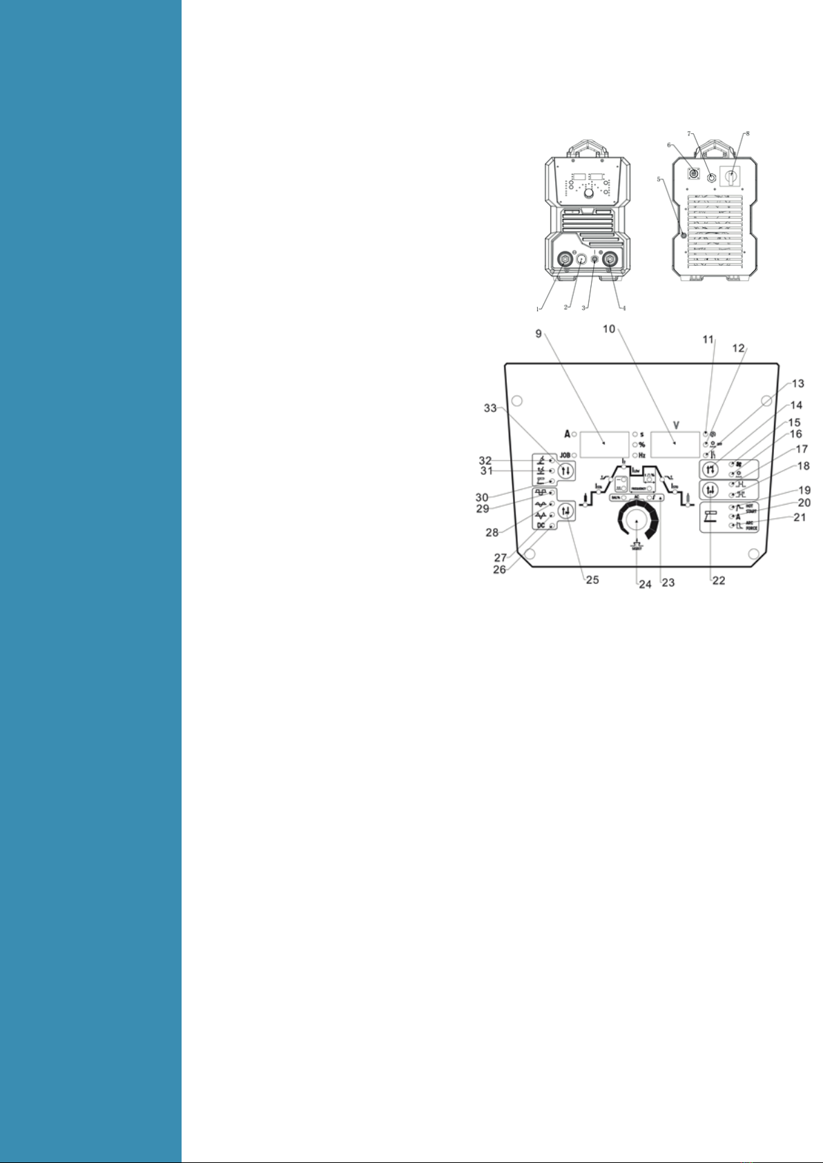
TIG welding current setting indicator (4)
Sets the main welding current. Unit(A) and setting range (10-320A/400A/500A).
Base current setting indicator (5)
Only available when pulse mode (12) is selected. Sets the current of the low/ base pulse. Unit(A)
and setting range (10-320A/400A/500A).
Down slope setting indicator (6)
When the trigger is released, the welding current will reduce gradually over the time selected down
to 0. This allows the operator to complete the weld without leaving a ‘crater’ at the end of the weld
pool. Unit(S) and setting range (0-10.0S).
End current setting indicator (7)
Available in 4T trigger mode only, sets a welding current 10-100% of the main welding current
activated when the trigger is held on to ‘unlatch’ the trigger before the weld is finished. If
downslope (6) is set, the current will go through the downslope period before going to the end
current set. When the trigger is released, the arc will stop.
Post gasflow setting indicator (8)
Controls the period of time the shielding gas continues to flow for after the arc is stopped. This
protects the weld area and torch tungsten from contamination while it is still hot enough to react with
atmospheric gases, after the weld is finished. Unit(S) and setting range (0-10.0S).
Pulse width setting indicator (9)
Only available when pulse mode (12) is selected. Sets the time proportion as a percentage between
the peak current and base current when using pulse mode. Neutral setting is 50%, the time period of
the peak current and base current pulse is equal. Higher pulse duty setting will give greater heat
input, while lower pulse duty will have the opposite effect. Unit(%) and setting range (5-95%).
Pulse frequency setting indicator (10)
Only available when pulse mode (12) is selected. Sets the rate that the welding output alternates
between the peak and base current settings. Unit(Hz) and setting range (0.5-999Hz).
Pulse mode ‘off’ indicator (11)
Pulse mode ‘On’ indicator (12)
Clean Width Area/ AC Balance Adjustment (13)
Only available in AC welding mode (27,28,29). Adjusts the balance as a percentage between the
forward and reverse current cycles when welding in AC output mode. The reverse part of the AC
cycle gives the ‘cleaning’ effect on the weld material, while the forward cycle melts the weld
material. Neutral setting is 0. Increased reverse cycle bias will give greater cleaning effect, less weld
penetration and more heat in the torch tungsten, which gives the disadvantage of reducing the
output current that can be used for a given tungsten size, to prevent the tungsten overheating.
Increased forward cycle bias will give the opposite effect, less cleaning effect, greater weld
penetration and less heat in the tungsten.
For maximum effectiveness, ideally the clean width/ AC balance should be set with as much forward
cycle bias as possible, while still maintaining a sufficient level of oxidisation removal for a
contamination free weld pool. The cleaner non-ferrous metal is before welding, the more effective it
is to weld. This effect can also be used to reduce heat in the tungsten, allowing use of a pointed
tungsten tip shape for a more defined arc. setting range (-5-+5).
AC Frequency Adjustment (14)
Only available in AC welding mode (27,28,29). Increasing AC frequency will focus the shape of the
arc, resulting in a tighter, more controlled arc causing increased penetration and less heated
affected area for the same current setting. Slower frequency will result in a wider, softer arc shape.
Unit(Hz) and setting range (50-250Hz).
AC/DC Output Modes
DC (Direct Current) Welding Output (26)
Suitable for TIG welding ferrous (iron based) metals such as mild steel and stainless steel, copper and
titanium. TIG welding reactive metals such as Aluminium, Magnesium and Zinc requires AC
(alternating current) output. When reactive metals are exposed to air they form an oxide layer that
insulates the base metal and prevents welding current flowing, it also contaminates the weld pool.
Reverse current flow is required to break through/ clean off this oxide layer so that welding can take
place, while the current flow during the positive cycle does the majority of the heating of the
weld pool area.

AC Triangle Wave Welding Output (27)
Reduced heat input for same current setting. Especially useful for welding thin metal.
AC Square Wave (28)
Focused arc for maximum penetration, fast travel speed with best directional control.
AC Sine Wave Welding Output (29)
Traditional AC TIG welding wave form. Quieter, ‘soft’ arc characteristic.
TIG Arc Starting Modes
TIG HF/ Lift Ignition Modes (31,32)
For TIGwelding process,contactof the torch tungsten to the workpiece will cause contamination of
the tungsten and the workpiece that will adversely affect the weld quality, especially when the
tungsten is electrically energised.
HF Ignition (High Frequency) sends a pulse of high energy electricity through the torch system that is
capable of ‘jumping’ between the tungsten and the workpiece, ensuring arc starting without any
contact between the tungsten and workpiece. The disadvantage of HF ignition is that the high ener-
gy electrical pulse creates significant electrical and radio signal interference, which limits its use
around sensitive electronic equipment such as computers.
Lift TIG Ignition is a compromise that minimises tungsten contamination while eliminating the electrical
interference of HF start systems. Lift arc starting works by lightly resting the tungsten on the work piece,
activating the torch trigger signal and then lifting the tungsten off. The control circuit will sense when
the tungsten is removed from the work piece and send a low powered pulse of electricity through the
tungsten that will cause the TIG arc to initiate. Because the tungsten is not ‘live’ when it is in contact
with the work, contamination is minimised.
Program/Job Memory
The welding machine has 9 memory/ job spaces that parameters can be saved to for easy recall.
To access a saved program, press and hold in the control knob (24) and the program number 1-9 will
show on the display, the ‘JOB’ indicator will be lit. Adjust to the program number required by rotating
the control knob. Once the program is accessed, it will automatically load. To return to normal
parameter settings, press the control knob again (which will also load the selected program) To save
parameters set as a program, press and hold the control knob for a few seconds and the display will
blink. The settings are now saved in the last program space that was selected. If setting parameters to
save as a program, ensure that you start with a program number that the data is OK to overwrite, as
the previous settings saved to that memory space will be lost.
Pulse welding
Pulse welding mode switches the welding output between a high and low current output in a cyclical
manner. When used correctly this function has substantial benefits in the TIG welding process including
greater weld penetration for less work heat input and greater control of the weld pool.
The basic theory for setting the base current using pulse mode is that the base current should be
sufficient to maintain the existing molten weld pool, while the peak current is sufficient to melt new
metal in order to move/ expand the molten weld pool. Increased pulse frequency will have the effect
of making the arc more tightly focused which is useful for fine stainless work and similar.
Pulsing can also be used to help move the weld pool, this technique is useful for welding out of position
or with materials that have higher viscosity weld pool. Higher pulse duty setting will give greater heat
input, while lower pulse duty will have the opposite effect.
Water Cooling
The welding machine ca ne supplied with the integrated water cooler. The correct coolant to use is a
mixture of Mono Propylene Glycol and water in a 1:3 ratio (25% propylene glycol. Pure water may
be used as a coolant liquid, though it is not recommended for the long term reliability of the water
cooling system as it does not have the lubrication properties of glycol and does not provide protection
against freezing. Ready to use coolant fluid can be purchased from authorised Strata dealers.
Do not operate a water cooled torch without the cooling system operating!

Water / Air Cooling Selection Button (14)
When using the integrated water cooling system with a water cooled torch, select the ‘water’ option
(16). This will activate the water cooler power (the water cooler must also be switched on the rear
panel) and the water cooling protection system. If using air cooled torch, select ‘Air’ option (15).
Note the welding machine comes standard with a water cooled torch system. Operating a water
cooled torch without water cooling will quickly cause serious damage to the torch. Damage to torch
or components due to lack of water is not covered under machine warranty.
MMA settings
Hot start (19)
Hot start provides extra power when the weld starts to counteract the high resistance of the electrode
and workpiece as the arc is started. setting range (0-10).
Arc force (21)
An MMA welding power source is designed to produce constant output current (CC).This means
with different types of electrode and arc length; the welding voltage varies to keep the current
constant. This can cause instability in some welding conditions as MMA welding electrodes will have
a minimum voltage they can operate with and still have a stable arc.
Arc Force control boosts the welding power if its senses the welding voltage is getting too low. The
higher the arc force adjustment, the higher the minimum voltage that the power source will allow.
This effect will also cause the welding current to increase. 0 is Arc Force off, 10 is maximum Arc Force.
This is practically useful for electrode types that have a higher operating voltage requirement or joint
types that require a short arc length such as out of position welds.
TIG settings
TIG 2T/4T Trigger Control
2T Mode (17)
The trigger is pulled and held on to activate the welding circuit, when the trigger is released, the
welding circuit stops.
4T Mode (18)
This is known as ’latching’ mode. The trigger is pulled once and released to activate the welding
circuit, pulled and released again to stops the welding circuit. This function is useful to longer welds as
the trigger is not required to be held on continuously. TIG series of welding machines also has more
current control options that can be used in 4T mode.
TIG Parameter Setting (23)
Pre gas flow setting indicator (1)
Pre-flow controls the period shielding gas will flow for when the torch is triggered before the arc starts.
This purges the work area of atmospheric gas which could contaminate the weld before the weld
starts. Unit(S) and setting range (0.1-2S).
Start current setting indicator (2)
Available in 4T trigger mode, sets a welding current 10-100% of the main welding current activated
when the trigger is held on to ‘latch’ the trigger before the main weld current is started. Once the
trigger is released, the current will go through the upslope (3) period if it is set, to the main welding
current (4).
Up slope setting indicator (3)
When the trigger is activated, the welding current will increase gradually over the time selected
up to the set main welding current (4). Unit(S) and setting range (0-10.0S).
3.2
Power
supply input
Connection
The TIG welding machine is designed to operate on a 3phase 380-400-440V AC power supply.
When the power supply voltage is over the safe work voltage, there are over voltage and under
voltage protection inside the welder, the alarm light will on, at the same time, the current output will
be cut off.
If the power supply voltage continually goes beyond the safe work voltage range, it will shorten the
welder life-span. The below measures can be used:
- Change the power supply input net. Such as, connect the welder with the stable power supply
voltage of distributor;
- Induce the machines using power supply in the same time;
- Set the voltage stabilization device in the front of power cable input.
3.3
Installation
& Operation
for MMA
Welding
3.3.1
Set up
installation
for MMA
Welding
Connection of Output Cables Two sockets are available on this welding machine. For MMA welding
the electrode holder is shown be connected to the positive socket, while the earth lead (work piece) is
connected to the negative socket, this is known as DCEP. However various electrodes require a
different polarity for optimum results and careful attention should be paid to the polarity, refer to the
electrode manufacturers information for the correct polarity.
DCEP: Electrode connected to “+”output socket.
DCEN: Electrode connected to“-” output socket.
MMA (DC): Choosing the connection of DCEN or DCEP according to the different electrodes. Please
refer to the electrode manual.
MMA (AC): No requirements for polarity connection.
(1) Connect the earth lead to “-”, tighten clockwise;
(2) Connect the earth clamp to the work piece. Contact with the work piece must be firm contact
with clean, bare metal, with no corrosion, paint or scale at the contact point.
(3) Connect the electrode lead to “+”, tighten clockwise;
(4) Each machine is equipped with a power cable should be based on the input voltage welding
power cable connected to the appropriate position, not to pick the wrong voltage;
(5) With the corresponding input power supply terminal or socket good contact and prevent
oxidation;
(6) With a multi meter measure the input voltage is within the fluctuation range;
(7) The power ground is well grounded.

3.3.2
Operation
for MMA
Welding
(1) According to the above method to install is correct, turn the power switch, so that the power
switch is “ON” position, then the power indicator light, the fan comes on, the device work properly.
(2) Set to ‘MMA’ welding mode.
(3) Set the welding parameters as required using the parameters control knob (following the
instructions in the previous section).
(4) Place the electrode into the electrode holder and clamp tight.
(5) Strike the electrode against the work piece to create and arc and hold the electrode steady to
maintain the arc.
(6) Commence welding. If necessary, readjust the Welding parameters control knob to obtain the
welding condition required.
(7) After completion of welding the Power Source should be left turned ON for 2 to 3 minutes. This
allows the fan to run and cool the internal components.
(8) Switch the ON/OFF Switch (located on the rear panel) to the OFF position.
NOTE:
- Note the polarity of wiring, the general DC welding wire in two ways. Selected according to the
technical requirements of welding the appropriate connection, if you choose incorrectly will result in
arc instability and spatter large adhesion and other phenomena, such cases can be quickly reversed
to joints.
- If the work piece distance from the welding machine, the second line(electrode holder and ground)
is longer, so choose the appropriate conductor cross-sectional area should be larger to reduce
cable voltage drop.
3.3.3
MMA
Welding
trouble sho-
oting
The following chart addresses some of the common problems of MMA welding. In all cases of
equipment malfunction, the manufacturer’s recommendations should be strictly adhered to and
followed.
NO. Trouble Possible Reason Suggested Remedy
1 No arc
Incomplete welding circuit Check earth lead is connected.
Check all cable connections.
No power supply Check that the machine is switched
on and has a power supply
Wrong mode selected Check the MMA selector switch is
selected
2
Porosity −small
cavities or holes
resulting from gas
pockets in weld
metal
Arc length too long
Shorten the arc length
Work piece dirty,
contaminated or moisture
Remove moisture and materials
like paint, grease, oil, and dirt,
including mill scale from base
metal
Damp electrodes
Use only dry electrodes
3 Excessive Spatter Amperage too high
Decrease the amperage or choose a
larger electrode
Arc length too long Shorten the arc length
Insufficient heat input
Increase the amperage or choose a
larger electrode
Work piece dirty,
contaminated or moisture
Remove moisture and materials
like paint, grease, oil, and dirt,
including mill scale from base
metal
4
Weld sits on top,
lack of fusion
Poor welding technique
Use the correct welding technique
or seek assistance for the correct
technique
5 Lack of
penetration
Insufficient heat input
Increase the amperage or choose a
larger electrode
Poor welding technique
Use the correct welding technique
or seek assistance for the correct
technique
Poor joint preparation
Check the joint design and fit up,
make sure the material is not too
thick. Seek assistance for the
correct joint design and fit up
6
Excessive
penetration - burn
through
Excessive heat input
Reduce the amperage or use a
smaller electrode
Incorrect travel speed
Try increasing the weld travel
speed
7
Uneven weld
appearance
Unsteady hand, wavering
hand
Use two hands where possible to
steady up, practise your technique
8
Distortion −
movement of base
metal during
welding
Excessive heat input
Reduce the amperage or use a
smaller electrode
Poor welding technique
Use the correct welding technique
or seek assistance for the correct
technique
Poor joint preparation and or
joint design
Check the joint design and fit up,
make sure the material is not too
thick. Seek assistance for the
correct joint design and fit up
9
Electrode welds
with different or
unusual arc
characteristic
Incorrect polarity
Change the polarity, check the
electrode manufacturer for correct
polarity

3.4
Installation
& Operation
for TIG
Welding
3.4.1
Set up
installation
for TIG
Welding
Switch the ON/OFF Switch (located on the rear panel) to OFF.
(1) Connect the earth lead to “+”, tighten clockwise; Connect the earth clamp to the work piece.
Contact with the work piece must be firm contact with clean, bare metal, with no corrosion,
paint or scale at the contact point.
(2) Connect the TIG torch cable to “-”, tighten clockwise.
(3) Connect TIG torch gas connection to the TIG gas outlet , ensuring all connections are tight.
(4) Connect TIG torch remote plug to remote socket,ensuring all connections are tight.
(5) If using a water cooled torch, Connect the water cooling lines from the TIG torch to the front of
the water cooler, ensuring the red and blue return and supply lines match the connectors.
(6) If using a water cooled torch, connect the water cooler interface cable from the rear of the
power source to the rear of the water cooler.
(7) Connect the gas regulator to the Gas Cylinder and connect the gas line to the Gas Regulator.
(8) Connect the gas line to the machine inlet gas connector via the quick push lock connector
located on the rear panel. Check for Leaks!
(9) Open gas cylinder valve and adjust regulator, flow should be between 5-10 l/min depending on
application. Re-check regulator flow pressure with torch valve open as static gas flow setting
may drop once gas is flowing.
(10) Each machine is equipped with a power cable should be based on the input voltage welding
power cable connected to the appropriate position, not to pick the wrong voltage;
NOTE:
-Secure the gas cylinder in an upright position by chaining them to a stationary support to prevent
falling or tipping.
3.4.2
Operation
for TIG
Welding
(1) According to the above method to install is correct, turn the power switch to the “ON” position,
the power L.E.D. light should illuminate, the fan comes on, the device work properly.
(2) Set the welding mode to ‘Lift TIG’ or ‘HF TIG’.
(3) If a water cooled torch and water cooler is used, check the water cooler has sufficient coolant
level and all connections are firmly secured, then switch on the water cooler power switch on the
rear of the water cooler. Set the water/air setting button (14) to ‘water (16)’. The water cooler
should now start operating.If using an air cooled torch, set the button (14) to ‘air’ setting (15).
(4) Set the welding parameters as required using the parameters control knob (following the
instructions in the previous section).
(5) The tungsten must be ground to a blunt point in order to achieve optimum welding results. It is
critical to grind the tungsten electrode in the direction the grinding wheel is turning.
(6) Install the tungsten with approximately 3mm to 7mm sticking out from the gas cup, ensuring you
have correct sized collet.
(7) Tighten the back cap.
(8) Commence welding. If necessary, readjust the parameters control knob to obtain the welding
condition re-quired.
(9) After completion of welding the Power Source should be left turned ON for 2 to 3 minutes. This
allows the fan to run and cool the internal components.
(10) Switch the ON/OFF Switch (located on the rear panel) to the OFF.

3.4.3
Remote
current
control
The welding machine can accept remote current control from a potentiometer/ analogue signal or
a digital up/down button signal. Potentiometer remote control will change the current from the 5A
minimum to the maximum set using the machine current control .Using an up/ down button remote
signal, the current may be increased or decreased in 1A increments, or ‘scrolls’ up to 30A at a time if
the button is held down. This is very useful for precision work.
Socket
Pin
Function
Potentiometer
Up/down
1
Not connected
Not connected
2
Not connected
Not connected
3
10k ohm (maximum) connection to 10k ohm
remote control potentiometer
Not connected
4
Wiper arm conne ction to 10k ohm remote
control potentiometer
Not connected
5
Zero ohm (minimum) connection to 10k ohm
remote control potentiometer
Not connected
6
Not connected
The button of "UP" input
7
Not connected
The button of "DOWN" input
8
Trigger Switch Input
9
Trigger Switch Input
10
Be shorted with 11
Not connected
11
Be shorted with 10
The button of "UP"& "DOWN" input
12
Not connected
Not connected
3.4.4
Tig Welding
Techniques
TIG Welding Fusion Technique
Manual TIG welding is often considered the most difficult of all the welding
processes. Because the welder must maintain a short arc length, great care and
skill are required to prevent contact between the electrode and the work piece.
Similar to Oxygen Acetylene torch welding, Tig welding normally requires two
hands and in most instances requires the welder to manually feed a filler wire
into the weld pool with one hand while manipulating the welding torch in the
other. However, some welds combining thin materials can be accomplished
without filler metal like edge, corner, and butt joints. This is known as Fusion
welding where the edges of the metal pieces are melted together using only
the heat and arc force generated by the TIG arc. Once the arc is started the
torch tungsten is held in place until a weld pool is created, a circular movement
of the tungsten will assist is creating a weld pool of the desired size. Once the
weld pool is established tilt the torch at about a 75° angle and move smoothly
and evenly along the joint while fusing the materials together.

TIG Welding with Filler Wire Technique
It is necessary in many situations with TIG welding to add a filler wire into the
weld pool to build up weld reinforcement and create a strong weld. Once
the arc is started the torch tungsten is held in place until a weld pool is
created, a circular movement of the tungsten will assist is creating a weld
pool of the desired size. Once the weld pool is established tilt the torch at
about a 75° angle and move smoothly and evenly along the joint. The filler
metal is introduced to the leading edge of the weld pool. The filler wire is
usually held at about a 15° angle and fed into the leading edge of the
molten pool, the arc will melt the filler wire into the weld pool as the torch is
3.4.5
Electrodes Tungsten Electrodes
Tungsten is a rare metallic element used for manufacturing TIG welding electrodes. The TIG process
relies on tungsten’s hardness and high-temperature resistance to carry the welding current to the arc.
Tungsten has the highest melting point of any metal, 3,410 degrees Celsius. Tungsten electrodes are
non-consumable and come in a variety of sizes, they are made from pure tungsten or an alloy of
tungsten and other rare earth elements. Choosing the correct tungsten depends on the material being
welded, amps required and whether you are using AC or DC welding current. Tungsten electrodes are
colour-coded at the end for easy identification.
T
ungsten Electrodes Rating for Welding Currents
Tungsten
Diameter
mm
DC Current Amps
Torch Negative
2% Thoriated
AC Current Amps
Un-Balanced Wave
0.8% Zirconiated
AC Current Amps
Balanced Wave
0.8% Zirconiated
1.0mm
15-80
15-80
20-60
1.6mm
70-150
70-150
60-120
2.4mm
150-250
140-235
100-180
3.2mm
250-400
225-325
160-250
4.0mm
400-500
300-400
200-320

Electrode Tip/Flat
The shape of the tungsten electrode tip is an important process variable in precision arc welding. A
good selection of tip/flat size will balance the need for several advantages. The bigger the flat, the
more likely arc wander will occur and the more difficult it will be to arc start. However, increasing the
flat to the maximum level that still allows arc start and eliminates arc wonder will improve the weld
penetration and increase the electrode life. Some welders still grind electrodes to a sharp point, which
makes arc starting easier. However, they risk decreased welding performance from melting at the tip
and the possibility of the point falling off into the weld pool.
Electrode Included Angle/Taper
DC Welding Tungsten electrodes for DC welding should be ground longitudinally and concentrically
with diamond wheels to a specific included angle in conjunction with the tip/flat preparation.
Different angles produce different arc shapes and offer different weld penetration capabilities. In
general, blunter electrodes that have a larger included angle provide the following benefits:
• Last Longer
• Have better weld penetration
• Have a narrower arc shape
• Can handle more amperage without eroding.
Sharper electrodes with smaller included angle provide:
• Offer less arc weld
• Have a wider arc
• Have a more consistent arc
The included angle determines weld bead shape and size. Generally, as the included angle increases,
penetration increases and bead width decreases.

3.4.6
TIG Welding
trouble
shooting
The following chart addresses some of the common problems of TIG welding. In all cases of equipment
malfunction, the manufacturer’s recommendations should be strictly adhered to and followed.
NO. Trouble Possible Reason Suggested Remedy
1 Tungsten burning
away quickly
Incorrect Gas or No Gas
Use pure Argon. Check cylinder
has gas, connected, turned on and
torch valve is open
Inadequate gas flow
Check the gas is connected, check
hoses, gas valve and torch are not
restricted.
Back cap not fitted correctly
Make sure the torch back cap is
fitted so that the o-ring is inside the
torch body
Torch connected to DC + Connect the torch to the DC- output
terminal
Incorrect tungsten being
used
Check and change the tungsten
type if necessary
Tungsten being oxidised
after weld is finished
Keep shielding gas flowing 10–15
seconds after arc stoppage. 1
second for each 10amps of weld
current.
Tungsten melting back
into the nozzle on AC
welding
Check that correct type of tungsten
is being used. Check the balance
control is not set too high on the
balance-reduce to lower setting
2
Contaminated
tungsten
Touching tungsten into the
weld pool
Keep tungsten from contacting
weld puddle. Raise the torch so that
the tungsten is off of the work
piece 2 - 5mm
Touching the filler wire to
the tungsten
Keep the filler wire from touching
the tungsten during welding, feed
the filler wire into the leading edge
of the weld pool in front of the
tungsten
Tungsten melting into the
weld pool
Check that correct type of tungsten
is being used. Too much current for
the tungsten size so reduce the amps
or change to a larger tungsten
3
Porosity - poor
weld appearance
and colour
Wrong gas / poor gas flow
/gas leak
Use pure argon. Gas is connected,
check hoses, gas valve and torch
are not restricted. Set the gas flow
between 6-12 l/min. Check hoses
and fittings for holes, leaks et
Contaminated base metal
Remove moisture and materials
like paint, grease, oil, and dirt from
base metal
Contaminated filler wire
Remove all grease, oil, or moisture
from filler metal
Incorrect filler wire
Check the filler wire and change
it if necessary

The welding machine can be configured to communicate exclusively with wireless foot pedal or remote
control panel. This is done by a simple process of synchronising the wireless remote control and the
machine frequencies. Each interface frequency assigned is unique, so it is possible to use several
wireless control systems/machines in the same area with no problems. The direct range of the machine
and the remote control.
Synchronization of the remote control with the welding machine,follow these instructions:
1) Ensure the welding power supply is switched off.
2) Press and hold the parameter select/adjust knob on the front panel of the power supply
(2-4 seconds) while at the same time turning the machine ON using the ON-OFF switch on the
back of the welding power supply.
3) When the display on the front panel of the power supply is blank, release the control knob. Turn on
the remote control or foot pedal while at the same time pressing any buttons on the remote
control panel or foot pedal, the digital meter on the front panel of the welding power supply flick
twice to indicate the synchronization is successful and complete.( Synchronization has to
accomplish in 10s after the display is blank.)
4) Switch the machine off and back on again to start welding operation.
5) If the operation is unsuccessful, repeat steps 1 to 4.
6) During operation, the front panel control on the power supply is still functional but the remote
control panel or foot pedal has higher priority level.
7) When the remote control panel or foot pedal is idles for 10 seconds, it will automatically go into
“sleep” mode.
8) Only front Panel Control is active when wireless remote control or foot pedal is in “sleep” mode.
Any operation on the wireless remote control panel or foot pedal will “wake it up and resumes
control of the machine.
How to remove the control function of Remote control box on welding machine
1) Ensure the welding power supply is switched off.
2) Press the encoder on the front control panel of the power supply, meanwhile turn on the machine.
3) Pressing the encoder about 10 seconds, until the control panel display "rSt", then it sucuceed.
On-off s witch
3.5
Remote
control
Configuration
3.5.1
Wireless
remote
control
Configuration

4
Yellowish residue /
smoke on the
alumina nozzle &
discoloured
tungsten
Incorrect Gas
Use pure Argon gas
Inadequate gas flow
Set the gas flow between 10 - 15
l/min flow rate
Inadequate post flow gas
Increase the post flow gas time
Alumina gas nozzle too
small
Increase the size of the alumina gas
nozzle
5 Unstable Arc
during welding
Torch connected to DC +
Connect the torch to the DC- output
terminal
Contaminated base metal
Remove materials like paint,
grease, oil, and dirt, including mill
scale from base metal.
Tungsten is contaminated Remove 10mm of contaminated
tungsten and re grind the tungsten
Arc length too long Lower torch so that the tungsten is
off of the work piece 2 - 5mm
6 HF present but no
welding power Incomplete welding circuit
Check earth lead is connected.
Check all cable connections. If
using a water cooled torch check
that the power cable is separated.
6 HF present but no
welding power
No gas
Check the gas is connected and
cylinder valve open, check hoses,
gas valve and torch are not
restricted
Set the gas flow between 10 - 15
l/min
Tungsten melting into the
weld pool
Check that correct type of tungsten
is being used. Too much current for
the tungsten size so reduce the
amps or change to a larger tungsten
7 Arc wanders
during welding
Poor gas flow
Check and set the gas flow between
10 - 15 l/min flow rate
Incorrect arc length Lower torch so that the tungsten is
off of the work piece 2 - 5mm
Tungsten incorrect or in poor
condition
Check that correct type of tungsten
is being used. Remove 10mm from
the weld end of the tungsten and re
sharpen the tungsten
Poorly prepared tungsten
Grind marks should run lengthwise
with tungsten, not circular. Use
proper grinding method and wheel.
Contaminated base metal or
filler wire
Remove contaminating materials
like paint, grease, oil, and dirt,
including mill scale from base
metal. Remove all grease, oil, or
moisture from filler metal
Incorrect filler wire
Check the filler wire and change if
necessary
8
Arc difficult to
start or will not
start welding
Incorrect machine set up
Check machine set up is correct
No gas, incorrect gas flow
Check the gas is connected and
cylinder valve open, check hoses,
gas valve and torch are not
restricted. Set the gas flow between
10 - 15 l/min flow rate
Incorrect tungsten size or
type
Check and change the size and or
the tungsten if required
Tungsten is contaminated
Remove 10mm of contaminated
tungsten and regrind the tungsten
Loose connection
Check all connectors and tighten
Earth clamp not connected to
work
Connect the earth clamp directly to
the work piece wherever possible
Loss of high frequency
Check torch and cables for cracked
insulation or bad connections.

3.5.2
Wire foot
pedal
Configuration
● When plug the twelve-lead aero-socket of pedal switch in it. Welder will identify the pedal switch,
the welding current knob on the front panel will can’t use,and only 2T can be selected.
● When use the adjustment knob of max-welding current beside the pedal, can set the max-current
you want.
Adjustment knob
of welding current
Connected to the 12 pin aero
socket on the front panel
Adjustment knob of max welding current
Socket Pin Function
1
Be shorted with 2
2
Be shorted with 1
3
20k ohm (maximum) connection to 20k ohm remote control potentiometer
4
Wiper arm connection to 20k ohm remote control potentiometer
5
Zero ohm (minimum) connection to 20k ohm remote control potentiometer
6
Not connected
7
Not connected
8
Trigger Switch Input
9
Trigger Switch Input
10
Not connected
11
Not connected
12
Not connected
3.6
Operation
environment ▲ Height above sea level ≤1000 M
▲ Operation temperature range -10〜+40°C
▲ Air relative humidity is below 90 %( 20°C)
▲ Preferable site the machine some angles above the floor level, the maximum angle does not
exceed 15℃.
▲ Protect the machine against heavy rain AND against direct sunshine.
▲ The content of dust, acid, corrosive gas in the surrounding air or substance cannot exceed normal
standard.
▲ Take care that there is sufficient ventilation during welding. There must be at least 30cm free
distance between the machine and wall.
Table of contents