Benning Tebevert III User manual

Tebevert III 25kVA
120VDC Inverter System
028-0009-006 Rev. C
Benning Power Electronics
1220 Presidential Drive Suite 100
Richardson, TX 75081 USA
www.benning.us
800.910.3601
This manual contains important
safety instructions that should be
followed during installation and
maintenance of the Power
System.
Operations and Maintenance Manual


TABLE OF CONTENTS
0IMPORTANT INFORMATION..................................................................................................................i
0.1 VERSION..............................................................................................................................i
0.1 PASSWORD..........................................................................................................................ii
0.1 DATA SHEET.......................................................................................................................iii
0.2 PREFACE .............................................................................................................................1
1SAFETY NOTES AND MARKINGS ........................................................................................ 3
2GENERAL ............................................................................................................................ 6
3THE COMPONENTS OF THE TYPICAL INVERTER SYSTEM.................................................. 6
3.1 PSJ TYPE EQUIPMENT CABINET..........................................................................................7
3.2 INVERTER SLOTS...............................................................................................................10
3.3 SBS SLOT ..........................................................................................................................12
3.4 MANUAL MAINTENCE BY-PASS SWITCH..............................................................................12
3.5 INVERTER..........................................................................................................................15
3.5.1 DESIGN OF THE UNIT.....................................................................................................15
3.5.2 TERMINALS AND OPERATING UNITS...............................................................................17
3.5.3 SIGNALLING...................................................................................................................19
3.6 ELECTRONIC SWITCH-OVER SBS UNIT ...............................................................................21
3.6.1 DESIGN OF THE UNIT.....................................................................................................22
3.6.2 TERMINALS AND OPERATING ELEMENTS.........................................................................23
3.6.3 SIGNALLING...................................................................................................................25
3.7 ACD DISTRIBUTIN PANEL...................................................................................................26
3.7.1 NA STYLE SNAP-IN BREAKER PANEL............................................................................26
3.7.2 DIN RAIL STYLE BREAKER PANEL...................................................................................27
3.8 TECHNICCAL DATA..................................................................................................................27
4INSTALLATION AND COMMISSIONING........................................................................... 28
4.1 INVERTER SETTINGS .........................................................................................................29
4.2 SETTINGS OF THE ELECTRONIC SWITCH –OVER/SBS UNIT.................................................30
4.3 PANEL WRITING ................................................................................................................32
4.3.1 DC CABLE REQUIREMENTS FOR 25kVA, 120, INDIVIDUAL DC INPUT (DIN RAIL TERMINAL
BLOCK).....................................................................................................................................34
4.3.2 DC CABLE REQUIREMENTS FOR 25kVA, 120VDC, BULK DC INPUT SYSTEM .......................34

4.3.3 AC CABLE REQUIREMENTS FOR 25kVA, 120 VAC AC INPUT RATINGS. .............................35
4.3.4 AC CABLE REQUIREMENTS FOR 25kVA, 120/240 VAC INPUT SYSTEM. ..............................35
4.3.5 AC CABLE REQUIREMENTS FOR 25kVA, 208 VAC INPUT SYSTEM......................................35
4.3.6AC CABLE REQUIREMENTS FOR 25kVA, 220 VAC INPUT SYSTEM .....................................36
4.3.7AC CABLE REQUIREMENTS FOR 25kVA, 240 VAC INPUT SYSTEM .....................................36
4.3.8AC CABLE REQUIREMENTS FOR 25kVA, 480 VAC INPUT SYSTEM ......................................36
4.3.9
TORQUE TABLE FOR ALL TERMINATIONS
........................................................................37
4.4 INSTALLATION OF THE UNITS............................................................................................60
4.4.1 INSTALLATION OF THE STATIC BY-PASS SWITCH (SBS)..................................................39
4.4.2 INSTALLATION OF THE INVERTERS ................................................................................40
4.5 SWITCHING ON THE INVERTER SYSTEM.............................................................................40
5 PERFORMANCE TESTING ................................................................................................. 42
5.1 PRELIMINARIES TO PERFORMANCE TEST ...........................................................................42
5.2 TEST EQUIPMENT..............................................................................................................43
5.3 TEST OF THE INVERTERS...................................................................................................43
5.3.1 INVERTER TEST ACTIVITIES...........................................................................................43
5.4 TEST OF THE SBS UNIT......................................................................................................45
5.4.1 SBS TEST ACTIVITIES ....................................................................................................46
5.5 FINAL STEPS......................................................................................................................47
6MAINTENANCE ................................................................................................................. 47
6.1 USE OF THE MANUAL BY-PASS SWITCH..............................................................................47
6.2 EXCHANGE OF UNITS.........................................................................................................50
6.3 UPGRADING THE SYSTEM ..................................................................................................51
7DESCRIPTION OF FUNCTION........................................................................................... 51
7.1 TOTAL SYSTEM..................................................................................................................51
7.2 INVERTER..........................................................................................................................52
7.2.1 MONITORING THE INPUT VOLTAGE...............................................................................52
7.2.2 MONITORING THE OUTPUT VOLTAGE.............................................................................54
7.2.3 MONITORING THE TEMPERATURE ..................................................................................54
7.2.4 OVERLOAD BEHAVIOR....................................................................................................54
7.2.5 SHORT-CIRCUIT BEHAVIOR............................................................................................55
7.3 ELECTRONIC SWITCHING/SBS UNIT...................................................................................55

VERSION:
Revision
Date
Originator
Approver
A 06.01.08 C.Tumey D.Almond
B 03.12.10 C.Tumey E.McDonald
C
07.08.11
A.Waggott/J.Almond
D.Almond
Publication Document: Version 1.1
Copyright © 2007 Benning Power Electronics
Proprietary Information: This manual contains proprietary information which is
protected by copyright law. All rights are reserved. No part of this manual may be
photocopied, reproduced, or translated to another language without prior written
consent of Benning Power Electronics. Specifications in this manual are subject to
change without notice.
i

PASSWORD:
Password Level 1: PW 1
Password Level 2: PW 2
Password Level 3: PW 3
Password Level 4: PW 4
NOTE:
PUT A SPACE BETWEEN PW AND THE
NUMBER
ii

Tebevert III_120 (R1_07) © Benning Power Electronics 2007
Specifications are subject to change without notice
Key Features
TEBEVERT III MODULAR
5-25 kVA INVERTER SYSTEM
The TEBEVERT III Modular Inverter System is designed
to address the critical AC powering requirements of
Industrial and Utility applications. The TEBEVERT III
Modular Inverter System can be scaled in 5 kVA
increments up to 25 kVA (non-redundant). Unlike
conventional stand alone inverters, these parallel
operating inverters can also be scaled to operate with
N+1 redundancy. N+1 redundancy insures optimal
availability for your critical load applications. If an
inverter failure should ever occur, the faulty inverter
module will automatically be removed from the output
bus before a disruption in the output is seen by the
critical load. In this mode of operation, a failure of one
inverter will not effect the operation of your critical load.
Since all units are designed for “hot swap” replacement,
a faulty module can easily be unplugged and replaced
to maintain power to your critical load.
Hot Swap 5 kVA Inverter Modules
Hot Swap Static Switch Module
Supports High Inrush Current Loads
High Efficiency Operation, Lowers Operating Costs
Low Distortion Output Voltage
Integrated Maintenance Bypass Switch
Meets EN 55022 Class B Requirements
Automatic Master-Slave Operation
Up to Five Inverter Modules Can Be Paralleled As Load
Increases
No Single Points Of Failure
User Friendly Display Of Operating Mode
Optional—Seismic Zone 4 Certified
Optional—Internal AC Load Distribution Circuit Breakers
120VDC Tebevert III
System

Tebevert III_120 (R1_07) © Benning Power Electronics 2007
Specifications are subject to change without notice
Technical Specifications
Benning Power Electronics, Inc. Toll Free: 800.910.3601
11120 Grader St . Dallas . TX 75238 Outside the US: 214.553.1444
E-Mail: sales@benning.us Fax: 214.553.1355
WEB:www.benning.us
60HZ Models
Output Capacity 5 - 25.0 KVA
Maximum Number of Modules The inverter cabinet supports a maximum of 5 inverter modules
Nominal Bypass AC Input 120 VAC 208, 220, 240, 480VAC
# of Bypass AC Phases 1 2
Bypass AC Input Wiring L, N, PE L1, L2, PE
Nominal DC Input 120VDC
DC Input Range -15%, +20%
Reflected DC Ripple, 120VDC < 2mV reverse smoothing
< 5% RMS
Nominal AC Output Voltage 120VAC 120VAC
Optional AC Output Voltage 120/240VAC 120/240VAC
Output Voltage Regulation +/- 5% for all combinations of line, load and temperature
Output Power Factor 0.7 lagging to 0.8 leading
Output Voltage Waveform PWM sine-wave
Output Crest Factor 2:8:1
Output Voltage Distortion < 3.5% @ 100% rated linear load
Output Overcurrent Protection Electronic current limiting
Overload Rating (Inverters) 200% for approx. 75 cycles (1.25 seconds)
Overload Rating (Static Bypass) 500% for 100ms
System Operating Efficiency > 89% (typical)
Frequency Stability +/- 0.1% free running, +/- 3% when AC present
Module Capacity 5.0kVA/4.0kW
Static Switch Transfer Time < 2ms
Cooling Temperature controlled fans
Maintenance Bypass Switch Standard make-before-break mechanically interlocked switch provided on all models
Remote Alarming (1) Form-C Summary Alarm, Optional Relay Card (8 Alarms)
LED indicators (Inverter Modules) Output present, fault, overload, AC synchronized, parallel operation
LED indicators (Static Bypass Switch) Power flow diagram, normal, fault, ac present, dc present, overload, load on bypass, load on
inverter
Metering (4) segment LCD display switchable between output voltage and current
Cabinet Dimensions (H x W x D) 84” (2134 mm) x 23.6” (600 mm) x 23.6” (600 mm)
Radio Interference EN 55022, class B
Altitude 6000 ft (1800 m), 13, 000 ft. (4000 m) at 30°C
Operating Temperature -5 to +40° C
Operating Humidity 0-95% non-condensing
Module Data 5.0kVA
Power Rating 5000VA/4000W
Nominal Input Current 120 VDC 38.0A
Maximum Input Current 120VDC 44A
Output Current NOM 120VAC 41.6A

TEBEVERT III INVERTER SYSTEM (120 VDC)
07.11.2011 1 028-0009-006
PREFACE
Congratulations and thank you for purchasing a Benning TEBEVERT III
Inverter System!
We at Benning are committed to supporting the needs of our customers by supplying
the customer with the proper information and documentation needed to properly install
and operate the unit purchased.
Important:
It is imperative that all the information be observed.
This avoids:
Danger during installation and operation.
Danger to operating personnel.
Downtime.
Increases the reliability and lifespan of the system.
This manual explains all the necessary information to unpack, install, and operate the
Benning BLI Inverter System and related components. Refer questions outside the
scope of this manual to our Customer Service Department.
Customer Service:
We are committed to excellence in dependability and customer satisfaction. If you have
any questions or problems, please contact the Customer Service Department at:
1.800.910.3601 or 214.553.1444 for more information.
Please read all instructions before installing or operating the equipment and save these
manuals for future reference.

TEBEVERT III INVERTER SYSTEM (120 VDC)
07.11.2011 2 028-0009-006
Switched-Mode Modular
Series TEBEVERT
(HOT-PLUG-Version)
Inverter System
Model:
5.0kVA-25.0kVA (120VDC Input, 120 VAC Output
Modules)
TEBEVERT III INVERTER SYSTEM (120 VDC)
07.11.2011 3 028-0009-006
1 SAFETY NOTES AND MARKINGS
This operating manual contains important information for the installation,
operation, and maintenance of the inverter system. This manual must be retained
and observed at all times!
Explanation of the symbols used:
Indicates safety instructions which must be followed to
avoid danger to persons!
Indicates instructions which must be followed to avoid
material damage!
All specifications in these operating instructions must be
observed at all times!
Index of abbreviations:
A Amps
AC Alternating Current
DC Direct Current
I Current
LVD Low Voltage Detector
CB Circuit Breaker
G Ground
L Line
N Neutral
SNMP Simple Network Management Protocol
V Volts
W Watts

TEBEVERT III INVERTER SYSTEM (120 VDC)
07.11.2011 4 028-0009-006
Further symbols, diagrams and pictures are explained at the appropriate
places within this operating manual.
Explanation of the abbreviations and definitions used:
SBS Static By-Pass Switch (SBS)
DVA Digital volt-ammeter
Mains Commercial AC input power source
By-pass Input Commercial AC Mains voltage providing an alternative AC
source to the connected load equipment. The By-pass
input is used by either the manual maintenance by-pass
or the SBS for back-up support in the event of an
inverter system failure.

TEBEVERT III INVERTER SYSTEM (120 VDC)
07.11.2011 5 028-0009-006
The inverter system is an electrical unit with dangerous
voltage and current levels. For this reason, the following
safety instructions must be observed.
1. Installation, operation, maintenance, and repair should be carried out in
strict accordance with the instructions in this document.
2. Ensure that only fully trained and qualified personnel have access to the
system. Only qualified and authorized personnel should be able to open
the units.
3. Even when the unit is completely switched off, some of its interior
components remain live as long as they are connected to the mains
supply or the battery.
4. Installed capacitors may be charged even when the system is
disconnected. These must be correctly discharged by a qualified
technician before the connections or terminals are touched.
5. When working at the unit, use properly insulated tools at all times which
are suitable for the levels of voltage concerned.
6. All persons working with the unit must be familiar with the first-aid
techniques to be adopted in cases of accidents involving electricity.
7. The regulations of the local power supply companies and all other
applicable safety regulations must be observed at all times.

TEBEVERT III INVERTER SYSTEM (120 VDC)
07.11.2011 6 028-0009-006
2 GENERAL
The TEBEVERT III family of modular inverter systems consists of: modular
hot-plug, inverters, and an electronic static by-pass switch (SBS). All
electrical connections are automatically disconnected or connected when
the modules are pulled out of or pushed into the system cabinet. This may
take place during normal operation without interruption in power to the
connected load equipment. This design provides an uninterrupted supply
of AC current and satisfies the highest requirements with respect to the
expansion of the system, ease of maintenance and operating safety.
The TEBEVERT III is available for DC voltages of 120VDC. Each inverter
module is available in 5.0kVA/4.0kW. Parallel operation of maximum of
five (5) inverter modules provides a maximum system rating of
25.0kVA/20kW. The output voltage is 120VAC or 120/240VAC and can be
adjusted to 50Hz or 60Hz according to the application.
Warning!
Several inverter systems may not be operated in parallel.
This may lead to the destruction of the inverter systems.
3 THE COMPONENTS OF THE TYPICAL INVERTER
SYSTEM
The design and arrangement of the components of the inverter system are
generally standardized.
The standard components are:
•(1) PSJ type equipment shelf
•5 positions for the inverters
•(1– 5) inverter modules
•(1) position for the static by-pass switch (SBS)
•(1) manual maintenance by-pass switch

TEBEVERT III INVERTER SYSTEM (120 VDC)
07.11.2011 7 028-0009-006
The input of the terminals and distribution positions within the cabinet
depend on the supplied configuration. Refer to the equipment elevation
drawing for specific terminal sizes and placement.
The inverter’s static by-pass switch is only operational when properly
installed into its corresponding position.
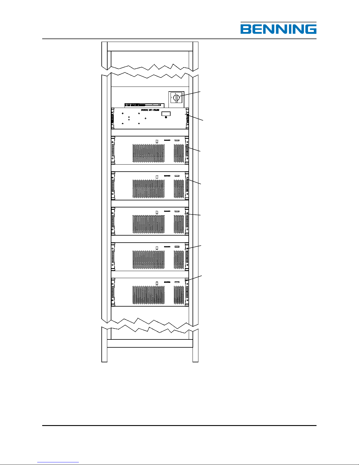
3.1 PSJ TYPE EQUIPMENT CABINET
The Benning TEBEVERT III system is built and supplied into a 19” PSJ
type, fully enclosed, floor standing cabinet (23.6” X 23.6” X 7’0” outside
overall dimension). Cabinets are available for New Equipment building
Standards (NEBS) and non-NEBS applications. Deep cabinets (600mm x
800mm or 23.6” x 31.5” x 7’0”) are available for special applications i.e.
raised floor, etc. consult with Benning at time of order.

TEBEVERT III INVERTER SYSTEM (120 VDC)
07.11.2011 8 028-0009-006
Input Terminals and distribution
position
(depending on the application)
Static By-Pass Switch (SBS) shelf
Inverter module shelf 5
(A5)
Inverter module shelf 4
(A4)
Inverter module shelf 3
(A3)
Inverter module shelf 2
(A2)
Inverter module shelf 1
(A1)
Transformers.
Fig. 1: Typical design of top feed cabinet
TEBEVERT III INVERTER SYSTEM (120 VDC)
07.11.2011 9 028-0009-006
Manual by-pass switch (Q10)
SBS module (A6)
Inverter Module 5 ( A5 )
Inverter Module 4 ( A4 )
Inverter Module 3 ( A3 )
Inverter Module 2 ( A2 )
Inverter Module 1 ( A1 )
Figure 2: Typical Inverter System (shown
with inverter modules, static by-pass)
0
12

TEBEVERT III INVERTER SYSTEM (120 VDC)
07.11.2011 10 028-0009-006
TYPICAL INPUT/OUTPUT TERMINALS FOR AN
INDIVIDUAL FEED CONFIGURATION
TYPICAL SNMP OPTION
Figure 3
Figure 4
TEBEVERT III INVERTER SYSTEM (120 VDC)
07.11.2011 11 028-0009-006
3.2 INVERTER MODULE SHELF
•Data line factory connected to the next inverter slot or the SBS slot (X1)
•Data connector for the inverter connection (X3)
•Load connector for the AC connection of the inverter output (X6) 3 poles
(2.5kVA) 5 poles (5.0kVA)
•Data line factory connected to the next inverter slot (X2)
•Female connector for the DC connection of the inverter (+)
•Female connector for the DC connection of the inverter
•Female connector for the protective earth of the inverter ( )
•*Each inverter carrier is equipped with two guiding rails insuring the
inverter is accurately positioned and a reliable contact is made.

TEBEVERT III INVERTER SYSTEM (120 VDC)
07.11.2011 12 028-0009-006
3.3 SBS MODULE SHELF
•Terminal block for the connection of the auxiliary DC supply to the SBS (X26)
•Terminal block for the voltage-free collective fault messaging system of the
inverter system (X25)
•Terminal block for the connection of the auxiliary contact signifying the by-
pass switch is in the “manual by-pass inverter” position (X27)
•Terminal block for the connection of the auxiliary contact signifying the by-
pass switch is in the "manual by-pass mains" position (X28)
•D-SUB connector for the optional connection of the inverter system to the
MCU remote monitoring system (X23)
•DIP switches, without function (S1)
•Data line to the inverter slot (X10) (This is used if there are inverters
arranged above the SBS. Not standard!)
•Manual by-pass switch with locking mechanism for the SBS (Q10)
•Female connector for the neutral contact mains input (N)
•Female connector for the neutral contact mains input (N)
Table of contents
Other Benning Inverter manuals


Popular Inverter manuals by other brands


Xantrex
Xantrex PROWATT SW SW 1000 owner's guide

MPP Solar
MPP Solar 1KVA-5KVA user manual

HiQ Solar
HiQ Solar TrueString TSXL380-8k-VN Installation & operator's manual

DeWalt
DeWalt DXGNI 2500 instruction manual

Outback Power Systems
Outback Power Systems FX 2012MT Specification sheet

Stephill
Stephill SE6000D4 Handbook


