Benning DSP 2500 User manual

DSP 2500
Inverter System
028-0009-200
Benning Power Electronics
11120 Grader Street
Dallas, TX 75238 USA
214.553.1444
800.910.3601
This manual contains
important safety instructions
that should be followed during
installation and maintenance
of the Power System.
Operations and Maintenance Manual


Preface
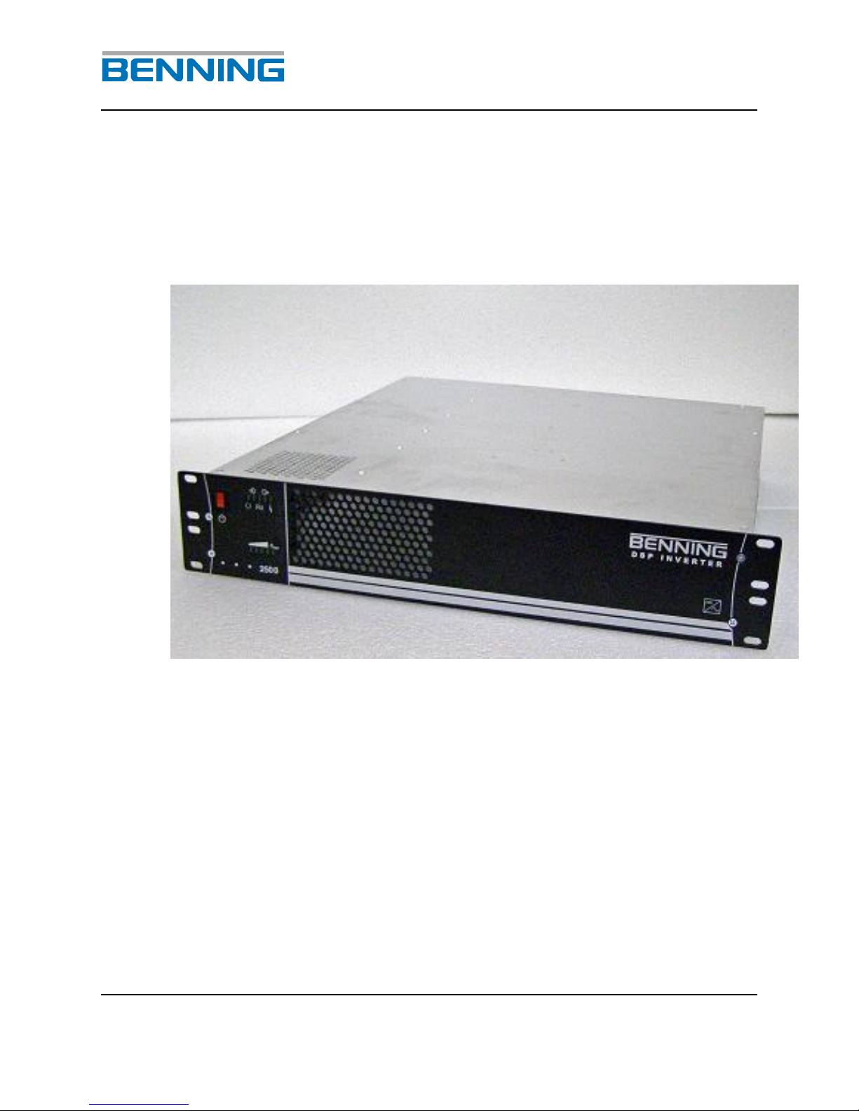
Congratulations and thank you for purchasing a Benning DSP 2500 Inverter
System.
We at Benning are committed to supporting the needs of our customers by supplying
the customer with the proper information and documentation needed to properly install
and operate the unit purchased.
Important:
It is imperative that all the information be observed.
This avoids:
Danger during installation and operation.
Danger to operating personnel.
Downtime.
Increases the reliability and lifespan of the system.
This manual explains all the necessary information to unpack, install, and operate the
Benning DSP 2500 Inverter System and related components. Refer questions outside
the scope of this manual to our Customer Service Department.
Customer Service:
We are committed to excellence in dependability and customer satisfaction. If you have
any questions or problems, please contact the Customer Service Department at:
1.800.910.3601 or 214.553.1444 for more information.
Please read all instructions before installing or operating the equipment and save these
manuals for future reference.

Revision
Date
Originator
Approver
A
10.15.07
C.Tumey
D.Almond
{Revision}
{Date}
{Originator}
{Approver}
{Revision}
{Date}
{Originator}
{Approver}
{Revision}
{Date}
{Originator}
{Approver}
{Revision}
{Date}
{Originator}
{Approver}
Publication Document: Version 1.0
Copyright © 2007 Benning Power Electronics
Proprietary Information: This manual contains proprietary information which is protected
by copyright law. All rights are reserved. No part of this manual may be photocopied,
reproduced, or translated to another language without prior written consent of Benning
Power Electronics. Specifications in this manual are subject to change without notice.

Table of Contents
1. SAFETY NOTES......................................................................................................2
2. GENERAL................................................................................................................3
3. INVERTER ...............................................................................................................4
4. DIMENSIONS OF THE UNIT....................................................................................5
Fig. 1: Dimension diagram of the DSP Inverter ......................................................5
5. TERMINALS AND OPERATING ELEMENTS .........................................................6
Fig. 2: Front view of the DSP Inverter.....................................................................6
Fig. 3: Rear view of the DSP inverter .....................................................................8
6. TECHNICAL DATA..................................................................................................9
7. ASSEMBLY AND COMMISSIONING ....................................................................18
8. DEVICE SETTINGS ...............................................................................................19
9. CONNECTING THE INVERTER ............................................................................19
10. INSTALLATION OF THE UNIT..............................................................................21
11. COMMISSIONING THE INVERTER ...................................................................22
12. MAINTENANCE / REPAIR .................................................................................22
13. DESCRIPTION OF FUNCTION ..........................................................................23
14. CONFIGURATION INDEX ..................................................................................25

DSP 2500 Inverter System
10.15.07 1 028-0009-200
Explanation of the symbols used:
Indicates safety instructions which must be followed to avoid
danger to persons!
Indicates instructions which must be followed to avoid
material damage!
All specifications in these operating instructions must be
observed at all times!
General instructions which must be observed

DSP 2500 Inverter System
10.15.07 2 028-0009-200
1. Safety Notes
The inverter is an electronic device which operates at
dangerous voltage and current levels.
For this reason, the following instructions must be followed at all times!
1. The inverter should be installed, operated, repaired and
maintained in accordance with the instructions in this document.
2. Only fully trained and qualified personnel should have access to
the system. Only qualified and authorized personnel should be
able to install the units.
3. Capacitors may be charged even when the unit is disconnected.
These must be correctly discharged by a qualified electrician
before the connections or terminals are touched.
4. When working with the unit, use properly insulated tools at all
times which are suitable for the levels of voltage concerned.
5. All persons working with the unit must be familiar with the first-
aid measures to be adopted in cases of accidents involving
electricity.
6. Always observe the regulations of the local operating company
as well as other safety regulations.
Attention!
The inverter may be operated at 120 (L1, N, G), 240 (L1-
N/L2-G) or 120/240 (L1-N-L2) systems.
The neutral conductor of the inverter is connected internally
to the protective wire. ( )

DSP 2500 Inverter System
10.15.07 3 028-0009-200
2. General
The inverters in the DSP can be utilized for a wide range of applications in the
field of telecommunications and other applications. The output power of the
inverter is 2500VA with 48VDC input model. The inverters utilize Digital Signal
Processor (DSP) technology, programmed with the appropriate algorithms to
carry out control and monitoring of the inverter. Please be aware that this unit is
designed for a 4 post cabinet installation and NOT for relay rack applications
unless a shelf is present.
Attention!
These inverters are designed for parallel operation
with limitations. To be submitted at a later release.
DSP 2500 Inverter System
10.15.07 4 028-0009-200
3. Inverter
The DC input voltage of 48 VDC is converted inside the inverter to an AC voltage
of 120, 240 or 120/240VAC at 60Hz.
DSP 2500 Inverter System
10.15.07 5 028-0009-200
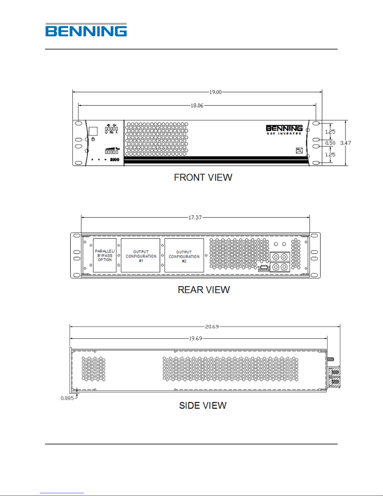
4. Dimensions of the Unit
Fig. 1: Dimension diagram of the DSP Inverter
DSP 2500 Inverter System
10.15.07 6 028-0009-200
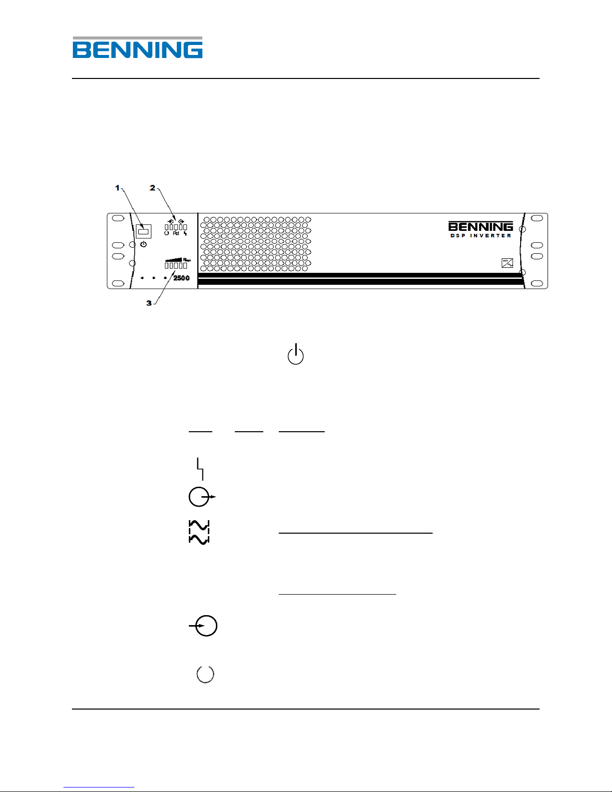
5. Terminals and Operating Elements
All operating elements are located on the front, installer connections are found on
the rear the inverter.
Fig. 2: Front view of the DSP Inverter
1Unit switch ON/OFF
2LED’s for indicating the inverter status
LED
Color
Meaning
red
Error
green
Output voltage present and connected
through to the load receptacles
green
LED in continuous operation:
The output voltage of the inverter is phase
locked to the other inverters in the system;
parallel operation only
LED in flashing mode:
MASTER functionality; parallel operation only
green
The DC input voltage is within the acceptable
input range. If light is blinking the DC voltage
is out of range.
green
Inverter ON
DSP 2500 Inverter System
10.15.07 7 028-0009-200
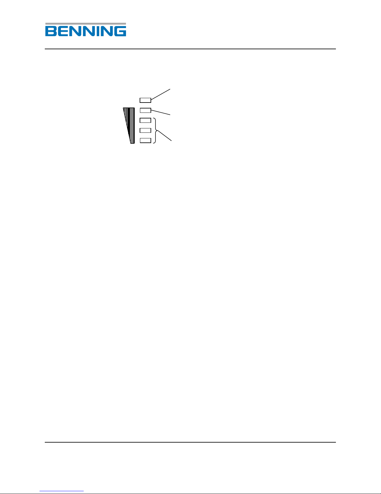
3 LED’s for signalling the actual inverter output power
The inverter is overloaded if the LED is flashing
(RED)
When this LED is lit the inverter is loaded nearly
to the limit (YELLOW)
The lit LED’s indicate the approximate load level.
(Green)
Pmax
DSP 2500 Inverter System
10.15.07 8 028-0009-200
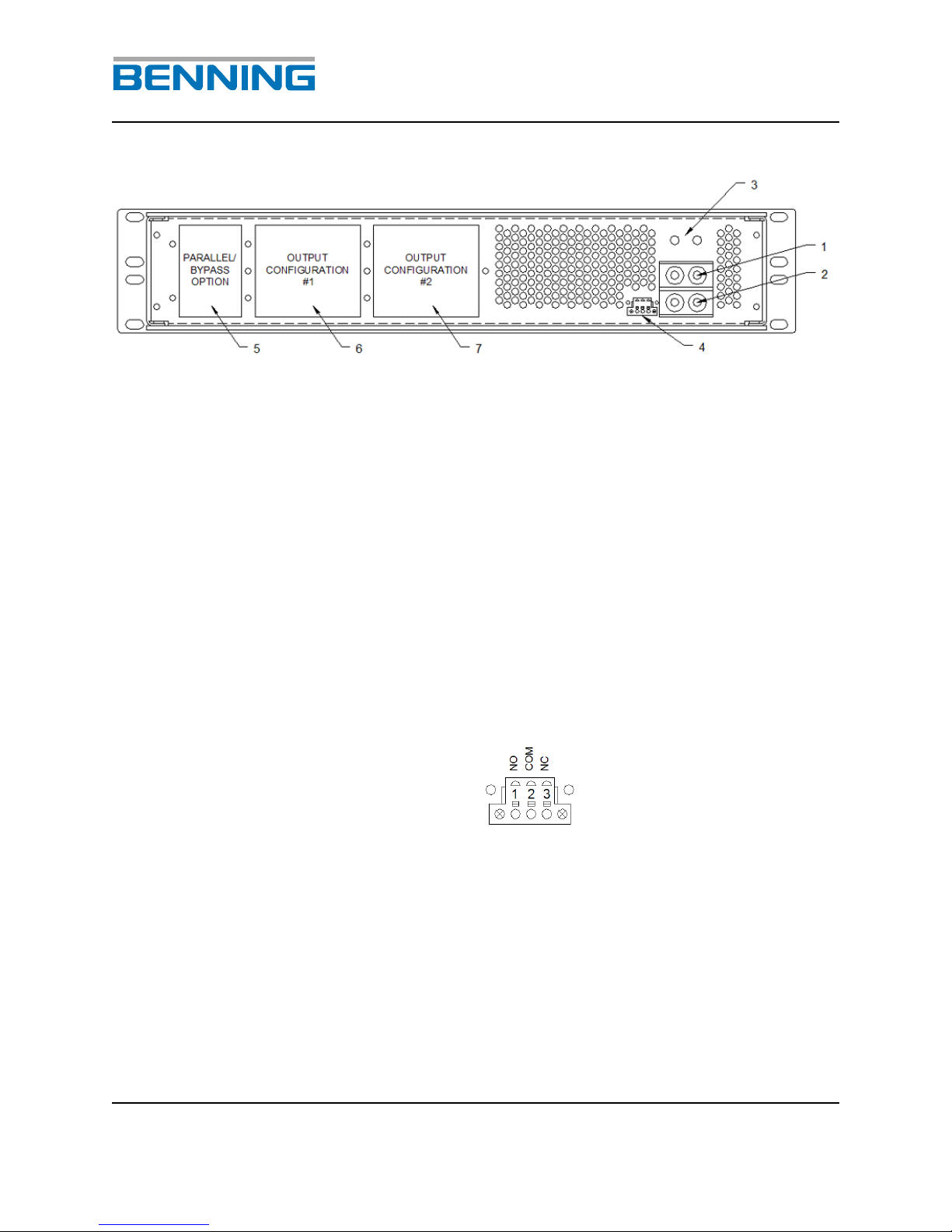
Fig. 3: Rear view of the DSP inverter
1(+); Copper bar / threaded stud; plus (+) connection for the DC
input of the inverter. Arranged for ¼” x 5/8”, two-hole crimp lug
2(-); Copper bar / threaded stud; negative (-) connection for the
DC input of the inverter. Arranged for ¼” x 5/8”, two-hole crimp
lug.
3Grounding location (PE).
4Potential free central fault signal.
5 Parallel Bypass Option Panel. (See section 14 for options)
6 Output Configuration #1 Panel. (See section 14 for options)
7 Output Configuration #2 Panel. (See section 14 for options)

DSP 2500 Inverter System
10.15.07 9 028-0009-200
6. Technical Data
Tebevert DSP (2500VA @ 120VAC)
The inverter module features DSP controlled high frequency, switch mode PWM
technology. The module converts the incoming DC voltage to computer grade
120VAC 60Hz power for use by the connected customer equipment.
DC Input
Nominal DC voltage: 48 VDC
Permissible deviation from the rated value: +20%; -15%
Input current at nominal real power
Rated voltage 100%: (48V) 47.0 A
Overvoltage 120%: (48V x 1.2V) 39.0 A
Undervoltage 85%: (48V x .85V) 55.0 A
Input current at no load operation at rated voltage: 1.4 A
Permissible ripple of input voltage: 5% eff.
Breaker or fuse requirement 70 AMP
AC Output
Alternating voltage: 120 VAC
Static voltage tolerance: 1%
Rated power (cos =0, 8): 2.5 kVA (total)
Nominal real power: 2.0 kW (total)
Rated current: (cos =0, 8) 20.8A @ 120VAC
Short-circuit behavior: >6000VA (total) for 4 s, after that cut-off
(DIN VDE 0100 - 410)
Overload behavior: 2xINfor 4 s, after that reduction to 1.2xINfor
60s,
after that unit turns off
Overload capacity-permanent: 1.1xIN(total)
Crest factor: 2.8
max. peak current 2.8xIN, the permissible
effective nominal current decreases in case of
higher crest factor
Frequency: 60Hz

DSP 2500 Inverter System
10.15.07 10 028-0009-200
Frequency stability: 0.1% crystal controlled
Distortion factor: 2% at linear load
Permissible power factor: cos = 0.7 ind. to cos = 0.8 cap.
Efficiency at nominal real power: > 88 %
Internal output fuse: T30A/250V
Physical/Environmental
Weight: 30 lbs.
Permissible temperature range (non condensing): 0°C .... +40°C without derating
+41°C ... +55°C with linear derating of 100% to 60%
output at a rate of 2.5%PN/°C
(shutdown at +55°C, automatic restart at +53°C)
Cooling mode: Temperature controlled forced cooling, front to
back
Color: Black Textured Powder Coat Faceplate
Radio interference degree: B (EN 55022)
Protection Class: UL 1950
Input/Output Connections
DC Input: Two pole terminal block accepting a 2 hole lug,
5/8”cc, ¼” studs, 1 AWG Max
(2AWG to 2/0 possible with narrow tongue lug)
Frame Ground: 5/8”cc, ¼” studs, 1 AWG Max
(2AWG to 2/0 possible with narrow tongue lug)
120VAC Output Options: Three NEMA 5-15 output receptacles protected by a
15A push to reset circuit breaker

DSP 2500 Inverter System
10.15.07 11 028-0009-200
Three NEMA Output receptacles protected by a 20A
push to reset circuit breaker
One 120VAC Bulk Terminal Block Output (L, N, G)
protected by a single-pole 30A rocker style breaker
Parallel Module Option: Dual RJ-45 receptacles and 120VAC Bulk Terminal
Block Input (L, N, and G) for parallel unit operation
Alarm: Potential free contact (NO, C, NC), issued when
Output AC is no longer present
Phoenix “Spring Clamp” style connector
Indicators
Optical Display: Output voltage present
Mains synchronized
Parallel module synchronized
Fault
Overload
Agency Approvals
Listed to UL 1950

DSP 2500 Inverter System
10.15.07 12 028-0009-200
Tebevert DSP (2500VA @ 240VAC)
The inverter module features DSP controlled high frequency, switch mode PWM
technology. The module converts the incoming DC voltage to computer grade
240VAC 60Hz power for use by the connected customer equipment.
DC Input
Nominal DC voltage: 48 VDC
Permissible deviation from the rated value: +20%; -15%
Input current at nominal real power
Rated voltage 100%: (48V) 47.0 A
Overvoltage 120%: (48V x 1.2V) 39.0 A
Undervoltage 85%: (48V x .85V) 55.0 A
Input current at no load operation at rated voltage: 1.4 A
Permissible ripple of input voltage: 5% eff.
Breaker or fuse requirement 70 AMP
AC Output
Alternating voltage: 240 VAC
Static voltage tolerance: 1%
Rated power (cos =0, 8): 2.5 kVA (total)
Nominal real power: 2.0 kW (total)
Rated current: (cos =0, 8) 10.7A @ 240VAC
Short-circuit behavior: >6000VA (total) for 4 s, after that cut-off
(DIN VDE 0100 - 410)
Overload behavior: 2xINfor 4 s, after that reduction to 1.2xINfor 60s,
after that unit turns off
Overload capacity-permanent: 1.1xIN(total)
Crest factor: 2.8
max. peak current 2.8xIN, the permissible effective
nominal current decreases in case of higher crest
factor
Frequency: 60Hz

DSP 2500 Inverter System
10.15.07 13 028-0009-200
Frequency stability: 0.1% crystal controlled
Distortion factor: 2% at linear load
Permissible power factor: cos = 0.7 ind. to cos = 0.8 cap.
Efficiency at nominal real power: > 88 %
Internal output fuse: T15A/250V
Physical/Environmental
Weight: 30 lbs.
Permissible temperature range (non condensing): 0°C .... +40°C without derating
+41°C ... +55°C with linear derating of 100% to 60%
output at a rate of 2.5%PN/°C
(shutdown at +55°C, automatic restart at +53°C)
Cooling mode: Temperature controlled forced cooling, front to
back
Color: Black Textured Powder Coat Faceplate
Radio interference degree: B (EN 55022)
Protection Class: UL 1950
Input/Output Connections
DC Input: Two pole terminal block accepting a 2 hole lug,
5/8”cc, ¼” studs, 1 AWG Max
(2AWG to 2/0 possible with narrow tongue lug)
Frame Ground: 5/8”cc, ¼” studs, 1 AWG Max
(2AWG to 2/0 possible with narrow tongue lug)
240VAC Output Options: Two IEC 320 (C13 or 19) output receptacles
protected by a 15A push to reset circuit breaker

DSP 2500 Inverter System
10.15.07 14 028-0009-200
One 240VAC Bulk Terminal Block Output (L1, L2, G)
protected by a double-pole 20A rocker style breaker
Parallel Module Option: Dual RJ-45 receptacles and 240VAC Bulk Terminal
Block Input (L1, L2, G) for parallel unit operation
Alarm: Potential free contact (NO, C, NC), issued when
Output AC is no longer present
Phoenix “Spring Clamp” style connector
Indicators
Optical Display: Output voltage present
Mains synchronized
Parallel module synchronized
Fault
Overload
Agency Approvals
Listed To UL 1950

DSP 2500 Inverter System
10.15.07 15 028-0009-200
Tebevert DSP (120/240VAC @ 2500VA)
The inverter module features DSP controlled high frequency, switch mode PWM
technology. The module converts the incoming DC voltage to computer grade
120/240VAC 60Hz power for use by the connected customer equipment.
DC Input
Nominal DC voltage: 48 VDC
Permissible deviation from the rated value: +20%; -15%
Input current at nominal real power
Rated voltage 100%: (48V) 47.0 A
Overvoltage 120%: (48V x 1.2V) 39.0 A
Undervoltage 85%: (48V x .85V) 55.0 A
Input current at no load operation at rated voltage: 1.4 A
Permissible ripple of input voltage: 5% eff.
Breaker or fuse requirement 70 AMP
AC Output
Alternating voltage: 120 VAC
Static voltage tolerance: 1%
Rated power (cos =0, 8): 2.5 kVA (total)
Nominal real power: 2.0 kW (total)
Rated current: (cos =0, 8) 20.8/10.4A @ 120/240VAC
Maximum Load Imbalance No greater than a +/- 10% L1 to L2 imbalance
Short-circuit behavior: >6000VA (total) for 4 s, after that cut-off
(DIN VDE 0100 - 410)
Overload behavior: 2xINfor 4 s, after that reduction to 1.2xINfor 60s,
after that unit turns off
Overload capacity-permanent: 1.1xIN(total)
Crest factor: 2.8
max. peak current 2.8xIN, the permissible effective
nominal current decreases in case of higher crest
factor
Frequency: 60Hz
Table of contents
Other Benning Inverter manuals


Popular Inverter manuals by other brands


SMA
SMA Inverter Manager installation manual

EINHELL
EINHELL BT-PG 4000 Original operating instructions

Mitsubishi Electric
Mitsubishi Electric FR-D700 Series instruction manual

TM
TM TMP Series instruction manual

Aeca
Aeca StecaGrid 8000 3ph Installation and operating manual

Cenga Power
Cenga Power BACKUP INVERTER user manual

MULTIQUIP
MULTIQUIP GA-6HA Starting instructions

Toshiba
Toshiba DEV002Z instruction manual

Outback Power Systems
Outback Power Systems FX Series installation manual

Omron
Omron SYSDRIVE MX2 SERIES user manual

Xantrex
Xantrex XPower 450 owner's manual

Tripp Lite
Tripp Lite PowerVerter DC-to-AC Inverter/Charger... owner's manual