BenQ mobile SL75 Setup guide

Release 1.1
Technical Documentation 10/2005
TD_Repair_L2.5L_SL75_R1.1.pdf Page 1 of 11
Service Repair Documentation
Level 3 (basic) – SL75
Release Date Department Notes to change
R 1.0 04.10.2005 BenQMobile CC S CES New document
R 1.1 05.01.2006 BenQMobile CC S CES Part modification
Company Confidential
2005©BenQ

Release 1.1
Technical Documentation 10/2005
TD_Repair_L2.5L_SL75_R1.1.pdf Page 2 of 11
Table of Content
1Introduction ...............................................................................................................................3
1.1 PURPOSE ...............................................................................................................................3
1.2 SCOPE ...................................................................................................................................3
1.3 TERMS AND ABBREVIATIONS ...................................................................................................3
2List of available level 3 (basic) parts.......................................................................................4
3Hardware requirements ............................................................................................................4
4SL75 Board layout.....................................................................................................................5
5SIM Card Problems ...................................................................................................................6
6IO Connector Problems ............................................................................................................7
7B to B connector (upper slider part) Problems ......................................................................8
8Battery connector Problems ....................................................................................................9
9Camera Connector Problems.................................................................................................10
10 Main keypad illumination Problems ......................................................................................10
Company Confidential
2005©BenQ

Release 1.1
Technical Documentation 10/2005
TD_Repair_L2.5L_SL75_R1.1.pdf Page 3 of 11
1 Introduction
1.1 Purpose
This Service Repair Documentation is intended to support Service partners to carry out repairs on
BenQ repair level 3. The described failures shall only be repaired in BenQ authorized local
workshops.
The level 3 (former Level 2.5light) partners are obliged to repair level 3 classified boards, up to their
repair level, under consideration of this repair instruction.
All repairs have to be carried out in an ESD protected environment and with ESD protected
equipment/tools. For all activities the international ESD regulations have to be considered.
Assembling/disassembling has to be done according to the latest SL75 Level 1-2 repair
documentation. It has to be ensured that every repaired mobile Phone is checked according to the
latest released General Test Instruction document (both documents are available in the Technical
Support section of the C-market).
Check at least weekly C-market for updates and consider all SL75 related Customer Care
Information
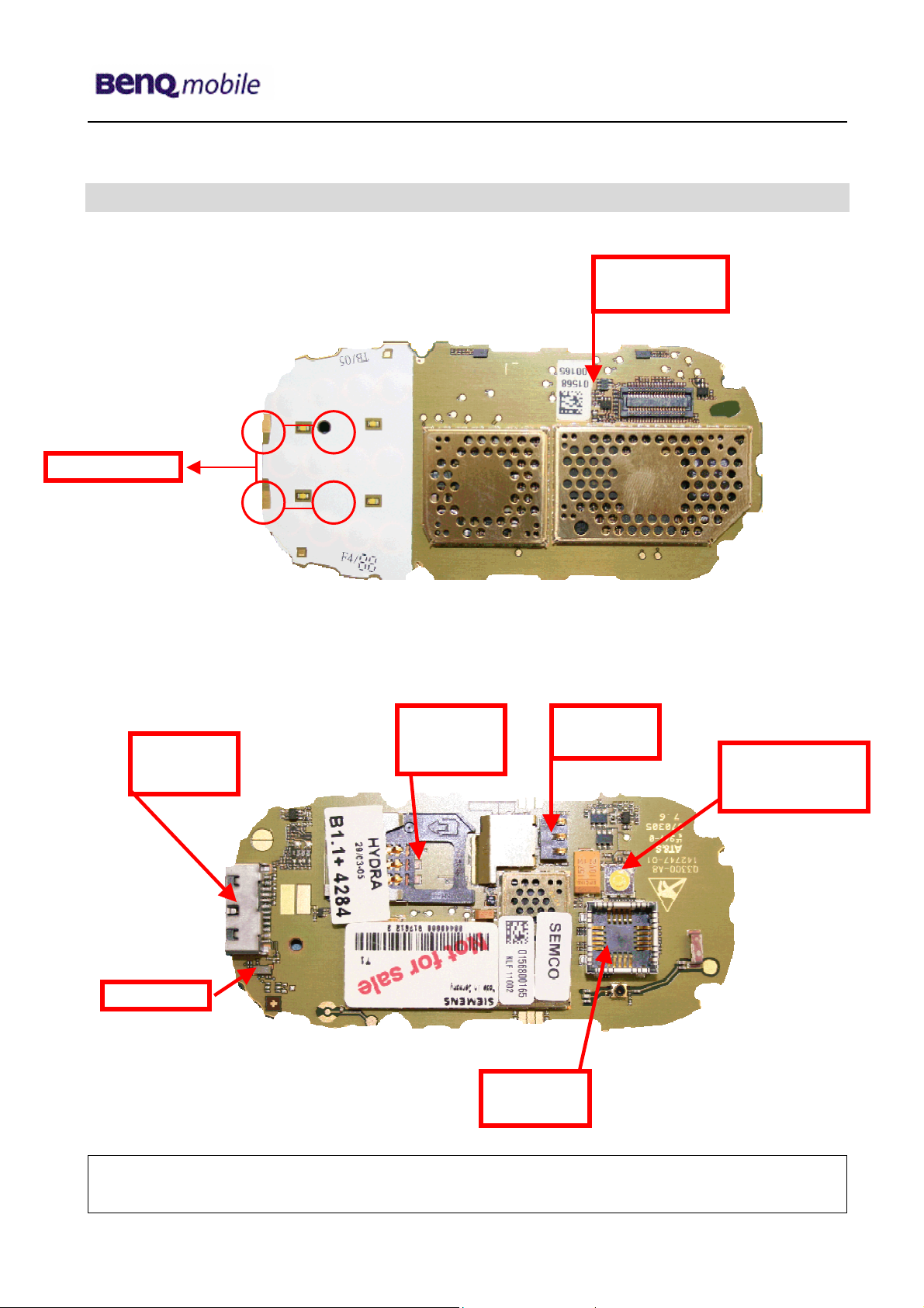
SL75 Partnumber on IMEI label: S30880-S2820-#xxx
, while # may be any letter (A-Z) and xxx may be any number from 100, 101, 102....
Scrap Handling: All Scrap information given in this manual are related to the
SCRAP-Rules and instructions.
Attention: Consider the new "LEAD-FREE" soldering rules (available in the communication
market), avoid excessive heat.
1.2 Scope
This document is the reference document for all BenQ mobile authorised Service Partners which are
released to repair BenQ mobile phones up to level 2.5 light.
1.3 Terms and Abbreviations
Company Confidential
2005©BenQ

Release 1.1
Technical Documentation 10/2005
TD_Repair_L2.5L_SL75_R1.1.pdf Page 4 of 11
2 List of available level 3 (basic) parts
(according to Component Matrix Vxx - check C-market for updates)
Product ID Order Number Description CM
SL75 V2802 L50640-L2109-D670 LED WHITE FLAT
SL75 V2803 L50640-L2109-D670 LED WHITE FLAT
SL75 V2804 L50640-L2109-D670 LED WHITE FLAT
SL75 V2805 L50640-L2109-D670 LED WHITE FLAT
SL75 V4902 L50640-L2108-D670 FLASH-LED HIGH BRIGHTN. WHITE
SL75 X1400 L36334-Z97-C213 CONNECTOR BATTERY 3-POL
SL75 X1504 L36334-Z93-C303 IO-JACK SLIM 12-POL
SL75 X1604 L36334-Z97-C335 CONNECTOR SIM CARD READER R65
SL75 X2750 L50697-F5004-F505 CONNECTOR BOARD TO BOARD 40-POL
SL75 X3500 L50634-Z97-C379 CONNECTOR CAMERA-SOCKET
SL75 Z1601 L50620-U6029-D670 FILTER EMI (Fi-Type7) PB Free
3 Hardware requirements
(according to General soldering information V1.3 - check C-market for updates)
Jigs, Tools and working materials for all described repairs:
hot air blower
soldering gun
tweezers
flux
solder
SL75 dome sheet jig
Company Confidential
2005©BenQ

Release 1.1
Technical Documentation 10/2005
TD_Repair_L2.5L_SL75_R1.1.pdf Page 5 of 11
4 SL75 Board layout
Upper board side
ow
L er board side
Connector
SIM Card
Reade
r
IO Jack
Slim
Connector
Battery
Flash-LED High
Board to Board
Connector
brightening
White
LED White Flat
Connector
Camera
Filter EMI
Company Confidential
2005©BenQ

Release 1.1
Technical Documentation 10/2005
TD_Repair_L2.5L_SL75_R1.1.pdf Page 6 of 11
5 SIM Card Problems
Fault Symptoms
Customer: GRT:
Handset does not accept SIM card SIM Card Problems
Connector SIM Card Reader
SIM Card Problems
Watch for oxidation and
damaged pads of the
SIM Card reader
caused by customer
SCRAP - has to be send
separately to WSC
not
oka
y
okay not
oka
y
Check the status of the
EMI Filter visually
Check the status of the
SIM Card reader visually
Use the resistor test
function of a multimeter
to check connection
between spring
contacts and soldering
contacts.
The value must be ~0
Exchange
SIM Card reade
r
Continue with
higher repair level
Exchange the
damaged Filter
okay
okay
okay
not
oka
y
not
oka
y
- check for twisted or
bent contacts
- check for dry joints
Back to customer
without repair
Use soldering iron to remove defective component. Avoid excessive heat! Watch surrounding components!
Resolder new component afterwards.
E-commerce order number: L50634-Z97-C406
E-commerce order name: CONNECTOR SIM CARD READER R65 (B)
Soldering temperature: ~ 360°C TIP Temp.
EMI Filter
Use hot air blower to remove defective component. Avoid excessive heat! Watch surrounding components!
Resolder new component afterwards.
E-commerce order number: L50620-U6029-D670
E-commerce order name: FILTER EMI (Fi-Type7) PB Free
Soldering temperature: ~ 360°C TIP Temp
IRIS Diagnose Code: 43300 Interface/SIM Card reader/Mechanical Damage
Company Confidential
2005©BenQ

Release 1.1
Technical Documentation 10/2005
TD_Repair_L2.5L_SL75_R1.1.pdf Page 7 of 11
6 IO Connector Problems
Fault Symptoms
Customer: GRT:
Charging Problems No connection to GRT
Problems with external loudspeaker or microphone when using a
car kit
Problems with accessories connected at the IO connector
Connector IO Jack
IO connector Problems
Watch for oxidation and
damaged pads of the
IO connector
caused by customer
SCRAP - has to be send
separately to WSC
not
oka
y
okay not
oka
y
Check the dust inside
the IO connector
Check the status of the
IO connector visually
Use the resistor test
function of a multimeter
to check connection
between spring
contacts and soldering
contacts.
The value must be ~0
Exchange
IO connecto
r
Continue with
higher repair level
Clean IO connector
okay
okay
okay
not
oka
y
not
oka
y
- check for twisted or
bent contacts
- check for dry joints
Back to customer
without repair
Use soldering iron to remove defective component. Avoid excessive heat! Watch surrounding
components! Resolder new component afterwards.
E-commerce order number: L36334-Z93-C303
E-commerce order name: IO-JACK SLIM 12-POL
Soldering temperature: ~ 360°C TIP Temp.
IRIS Diagnose Code: 46100 Interface/Charging Connector/Mechanical Damage
47300 Interface/Data Interface/Mechanical Damage
4B100 Interface/Headset Connector/Mechanical Damage
Company Confidential
2005©BenQ

Release 1.1
Technical Documentation 10/2005
TD_Repair_L2.5L_SL75_R1.1.pdf Page 8 of 11
7 B to B connector (upper slider part) Problems
Fault Symptoms
Customer: GRT:
Upper slider keyboard malfunction Keyboard malfunction
Upper slider keypad illumination does not work Current measured failed
Display problems
B to B connector problems
Watch for oxidation and
damaged pads of the
B to B connector
caused by customer
SCRAP - has to be send
separately to WSC
not
oka
y
okay
Check the status of the
B to B connector visually
Exchange
B to B
connector
okay
- check for twisted or
bent contacts
- check for dry joints
Continue with
higher repair level
Back to customer
without repair
not
oka
y
Connector Board to Board
Use hot air blower to remove defective component. Avoid excessive heat! Watch surrounding
components! Resolder new component afterwards.
E-commerce order number: L50634-Z97-C340
E-commerce order name: BOARD TO BOARD 30-POL
Soldering temperature: ~ 360°C TIP Temp.
IRIS Diagnose Code: 32100 Keys / Main / No Function
32200 Keys / Main / Reduced Functionality
36000 Keys / Illumination
Company Confidential
2005©BenQ

Release 1.1
Technical Documentation 10/2005
TD_Repair_L2.5L_SL75_R1.1.pdf Page 9 of 11
8 Battery connector Problems
Fault Symptoms
Customer: GRT:
Mobile does not switch on No connection to GRT
Battery connector problems
Watch for oxidation and
damaged pads of the
battery connector
caused by customer
SCRAP - has to be send
separately to WSC
not
oka
y
okay
Check the status of the
battery connector
visuall
y
Exchange
battery
connector
Continue with
higher repair level
okay
okay
Use the resistor test
function of a multimeter
to check connection
between spring
contacts and soldering
contacts. The value
must be ~ 0.
not
oka
y
not
oka
y
- check for twisted or
bent contacts
- check for dry joints
Back to customer
without repair
Connector BATTERY
Use hot air blower to remove defective component. Avoid excessive heat! Watch surrounding
components! Resolder new component afterwards.
E-commerce order number: L36334-Z97-C213
E-commerce order name: CONNECTOR BATTERY 3-POL
Soldering temperature: ~ 360°C TIP Temp.
IRIS Diagnose Code: 13000 Battery/Mechanical Damage
Company Confidential
2005©BenQ

Release 1.1
Technical Documentation 10/2005
TD_Repair_L2.5L_SL75_R1.1.pdf Page 10 of 11
9 Camera Connector Problems
Fault Symptoms
Customer: GRT:
Camera malfunction Tbd.
Camera connector Problems
Watch for oxidation and
damaged pads of the
camera connector
caused by customer
SCRAP - has to be send
separately to WSC
not
oka
y
okay
Check the status of the
camera connector
visuall
y
Use the resistor test
function of a multimeter
to check connection
between spring
contacts and soldering
contacts.
The value must be ~0
Exchange
camera
connector
Continue with
higher repair level
okay
not
oka
y
not
oka
y
- check for twisted or
bent contacts
- check for dry joints
Back to customer
without repair
Connector CAMERA
Use hot air blower to remove defective component. Avoid excessive heat! Watch surrounding
components! Resolder new component afterwards.
E-commerce order number: L50634-Z97-C379
E-commerce order name: CONNECTOR CAMERA-SOCKET
Soldering temperature: ~ 360°C TIP Temp.
IRIS Diagnose Code: BA000 Accessories / Camera
10 Main keypad illumination Problems
Company Confidential
2005©BenQ

Release 1.1
Technical Documentation 10/2005
TD_Repair_L2.5L_SL75_R1.1.pdf Page 11 of 11
Fault Symptoms
Customer: GRT:
Main keypad illumination does not work Current measured failed
LED Problems
Watch for oxidation and
damaged pads of the
LED’s
caused by customer
Back to customer
without repair
SCRAP - has to be send
separately to WSC
not
oka
y
okay
Check the status of the
battery connector
visuall
y
Use the diode test
function of a multimete
r
to check the status of
the diode. The typical
voltage drop on the
diode is 1.7 V when
testing the diode
function with the
multimeter.
Exchange
keypad LED’s
Continue with
higher repair level
okay
not
oka
y
not
oka
y
- check for twisted or
bent contacts
- check for dry joints
LED WHITE TOP
Use soldering iron to remove defective component. Avoid excessive heat! Watch surrounding
components! Resolder new component afterwards.
Attention: Remove Metal Dome Sheet before!!!
E-commerce order number: L36840-L2099-D670
E-commerce order name: LED WHITE TOP
Soldering temperature: ~ 360°C TIP Temp.
IRIS Diagnose Code: 36000 Keys/Illumination
Company Confidential
2005©BenQ
Table of contents
Other BenQ mobile Cell Phone manuals

BenQ mobile
BenQ mobile M315 Setup guide

BenQ mobile
BenQ mobile S88 User manual

BenQ mobile
BenQ mobile EF51 User manual

BenQ mobile
BenQ mobile S88 Setup guide

BenQ mobile
BenQ mobile EF51 User manual

BenQ mobile
BenQ mobile S68 User manual

BenQ mobile
BenQ mobile A38 User manual

BenQ mobile
BenQ mobile S75 User manual

BenQ mobile
BenQ mobile A38 User manual