BENSHAW RediStart EXEXMVRMX3 Series User manual

Motor Starter Card Set: BIPC-450100-02-01
Software Version 1: 810023-02-01
Software Version 2: 810024-01-01
Gate Driver Card: BIPC-300003-01
Gate Power Distributor Card: BIPC-300007-02
2006 Benshaw Inc.
©
890034-06-00
Solid State Starter
Control
RediStart TM
User Manual
MVRMX36 Models
10KV to 13.8KVAC
Benshaw retains the right to change specifications and illustrations in text without prior notification. The contents of this document may
not be copied without the explicit permission of Benshaw.


TRADEMARK NOTICE
Benshaw and are registered trademarks of Benshaw Incorporated.
UL is a trademark of Underwriters Laboratories, Incorporated.
Important Reader Notice
Congratulations on the purchase of your new Benshaw RediStart EXMVRMX3Solid State Starter. This manual contains the information to
install and program the EXMVRMX3Solid State Starter.
This manual may not cover all of the applications for the RediStart EXMVRMX3. Also, it may not provide information on every possible
contingency concerning installation, programming, operation, or maintenance specific to the RediStart EXMVRMX3Series Starters.
The content of this manual will not modify any prior agreement, commitment or relationship between the customer and Benshaw. The sales
contract contains the entire obligation of Benshaw. The warranty enclosed within the contract between the parties is the only warranty that
Benshaw will recognize and any statements contained herein do not create new warranties or modify the existing warranty in any way.
Any electrical or mechanical modifications to Benshaw products without prior written consent of Benshaw will void all warranties and may also
void cUL listing or other safety certifications, unauthorized modifications may also result in product damage operation malfunctions or personal
injury.
Incorrect handling of the starter may result with an unexpected fault or damage to the starter. For best results on operating the RediStart MX3
starter, carefully read this manual and all warning labels attached to the starter before installation and operation. Keep this manual on hand for
reference.
Do not attempt to install, operate, maintain or inspect the starter until you have thoroughly read this manual and related documents carefully
and can use the equipment correctly.
Do not use the starter until you have a full knowledge of the equipment, safety procedures and instructions.
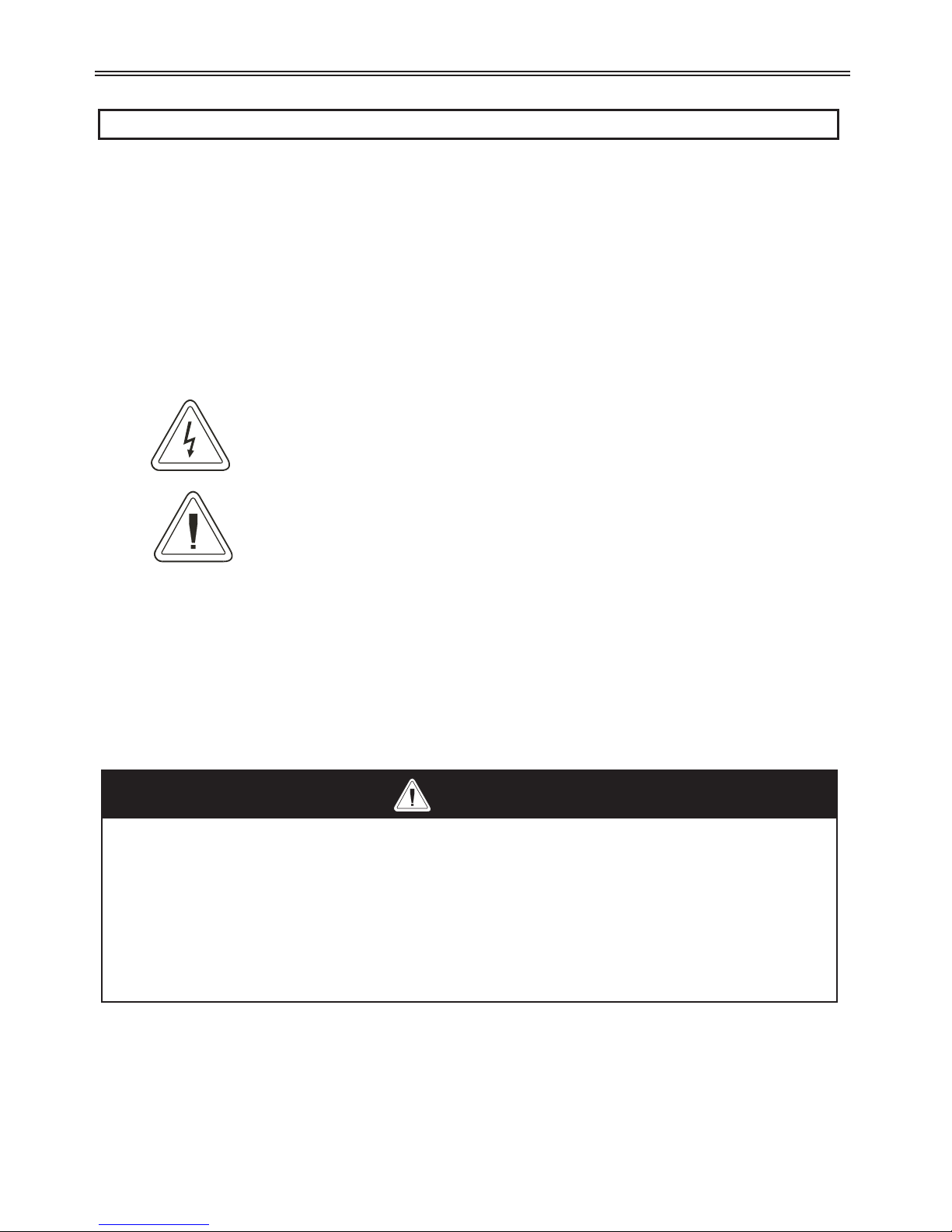
This instruction manual classifies safety instruction levels under "WARNING" and "CAUTION".
Electrical Hazard that could result in injury or death.
Caution that could result in damage to the starter.
Highlight marking an important point in the documentation.
Please follow the instructions of both safety levels as they are important to personal safety.
High Voltage
Motor control equipment and electronic controllers are connected to hazardous line voltages. When servicing starters and electronic
controllers, there may be exposed components with housings or protrusions at or above line potential. Extreme care should be taken
to protect against shock.
Stand on an insulating pad and make it a habit to use only one hand when checking components. Always work with another person
in case an emergency occurs. Disconnect power before checking controllers or performing maintenance. Be sure equipment is
properly grounded. Wear safety glasses whenever working on electronic controllers or rotating machinery.

Safety Precautions
Electric Shock Prevention
•While power is on or soft starter is running, do not open the front cover. You may get an electrical shock.
•This soft starter contains high voltage which can cause electric shock resulting in personal injury or loss of life.
•Be sure all AC power is removed from the soft starter before servicing.
•Do not connect or disconnect the wires to or from soft starter when power is applied.
•Make sure ground connection is in place.
•Always install the soft starter before wiring. Otherwise, you may get an electrical shock or be injured.
•Operate the switches with dry hands to prevent an electrical shock.
•Risk of Electric Shock - More than one disconnect switch may be required to de-energize the equipment before servicing.
Injury Prevention
•Service only by qualified personnel.
•Make sure power-up restart is off to prevent any unexpected operation of the motor.
•Make certain proper shield installation is in place.
•Apply only the voltage that is specified in this manual to the terminals to prevent damage.
Transportation and Installation
•Use proper lifting gear when carrying products, to prevent injury.
•Make certain that the installation position and materials can withstand the weight of the soft starter. Refer to the installation
information in this manual for correct installation.
•If parts are missing, or soft starter is damaged, do not operate the RediStart EXMVRMX3.
•Do not stand or rest heavy objects on the soft starter, as damage to the soft starter may result.
•Do not subject the soft starter to impact or dropping.
•Make certain to prevent screws, wire fragments, conductive bodies, oil or other flammable substances from entering the soft
starter.
Trial Run
•Check all parameters, and ensure that the application will not be damaged by a sudden start-up.
Emergency Stop
•To prevent the machine and equipment from hazardous conditions if the soft starter fails, provide a safety backup such as an
emergency brake.
Disposing of the RediStart EXMVRMX3
•Never dispose of electrical components via incineration. Contact your state environmental agency for details on disposal of
electrical components and packaging in your area.
i
SAFETY PRECAUTIONS

Table of Contents
1 INTRODUCTION ....................................... 2
2 TECHNICAL SPECIFICATIONS ..............................8
2.1 General Information...................................... 8
2.2 Electrical Ratings ....................................... 8
2.2.1 Terminal Points and Functions ................................ 8
2.2.2 Measurements and Accuracies ................................ 10
2.2.3 List of Motor Protection Features ............................... 10
2.2.4 Solid State Motor Overload .................................. 11
2.2.5 CT Ratios ............................................ 12
2.2.6 Optional RTD Module Specifications ............................ 12
2.2.7 Optional Zero Sequence Ground Fault CT.......................... 13
2.3 Sample RediStart EXMVRMX3Unit ............................. 14
2.4 Environmental Conditions .................................. 15
2.5 Altitude Derating ....................................... 15
2.6 Real Time Clock ........................................ 15
2.7 Approvals ........................................... 15
2.8 Certificate of Compliance ................................... 15
3 INSTALLATION........................................ 18
3.1 Before You Start ........................................ 18
3.1.1 Installation Precautions .................................... 18
3.1.2 Safety Precautions ....................................... 18
3.2 Installation Considerations .................................. 19
3.2.1 Site Preparation......................................... 19
3.2.2 EMC Installation Guidelines ................................. 19
3.2.3 R-Rated Motor Starter Fuses ................................. 19
3.2.4 Use of Electro-Mechanical Brakes .............................. 19
3.2.5 Reversing Contactor ...................................... 19
3.2.6 Use of Power Factor Capacitors................................ 20
3.3 Mounting Considerations................................... 21
3.3.1 Bypassed Starters........................................ 21
3.4 Wiring Considerations .................................... 21
3.4.1 Wiring Practices ........................................ 21
3.4.2 Considerations for Control and Power Wiring ....................... 21
3.4.3 Considerations for Signal Wiring ............................... 21
3.4.4 Meggering a Motor....................................... 21
3.4.5 High Pot Testing ........................................ 21
3.5 Typical Wiring Schematics .................................. 22
3.5.1 EXMVRMX3Power Wiring Schematic ............................ 22
3.5.2 EXMVRMX3Control Wiring Schematic ........................... 23
ii
TABLE OF CONTENTS

3.6 Power Wiring ......................................... 24
3.6.1 Recommended Wire Gauges ................................. 24
3.6.2 Power Wire Connections ................................... 24
3.6.3 Motor Lead Length....................................... 24
3.6.4 Compression Lugs ....................................... 24
3.6.5 Torque Requirements for Power Wiring Terminations................... 25
3.7 Current Transformers ..................................... 26
3.7.1 CT Mounting .......................................... 26
3.7.2 CT Polarity ........................................... 26
3.7.3 Zero Sequence Ground Fault Current Transformer..................... 26
3.8 EXMVRMX3Control Card Layout .............................. 28
3.9 EXMVRMX3I/O Card Layout ................................ 29
3.10 EXMVRMX3Terminal Block Layout ............................ 30
3.11 Control Wiring ........................................ 31
3.11.1 Control Power ......................................... 31
3.11.2 Output Relays ......................................... 31
3.11.3 Digital Input ......................................... 32
3.11.4 Analog Input ......................................... 33
3.11.5 Analog Output ........................................ 33
3.11.6 SW1 DIP Switch ........................................ 33
3.11.7 Motor PTC ........................................... 34
3.11.8 RTD Module Connector ................................... 34
3.12 Remote LCD Keypad/Display ............................... 35
3.12.1 Remote Display ........................................ 35
3.12.2 Display Cutout ........................................ 36
3.12.3 Installing Display ....................................... 36
3.13 RTD Module Installation .................................. 37
3.13.1 Location ............................................ 37
3.13.2 Modbus Address ....................................... 37
3.13.3 Power Connections ...................................... 37
3.13.4 RS-485 Communication ................................... 37
3.13.5 RTD Connections ....................................... 38
3.13.6 RTD Temperature vs. Resistance .............................. 38
4 KEYPAD OPERATION .................................... 40
4.1 Introduction .......................................... 40
4.2 Description of the LEDs on the Keypad ...........................40
4.3 Description of the Keys on the Remote LCD Keypad ...................41
4.4 Alphanumeric Display .................................... 42
4.4.1 Power Up Screen ........................................ 42
4.4.2 Operate Screen ......................................... 42
4.4.3 Parameter Group Screens ................................... 43
4.4.4 Meter Pages ........................................... 44
4.4.5 Fault Log Screen ........................................ 45
4.4.6 Fault Screen ........................................... 45
4.4.7 Event Recorder ......................................... 45
4.4.8 Lockout Screen ......................................... 46
4.4.9 Alarm Screen .......................................... 47
4.5 Procedure for Setting Data .................................. 47
iii
TABLE OF CONTENTS

4.6 Jump Code ........................................... 48
4.7 Restoring Factory Parameter Settings ............................48
4.8 Resetting a Fault ........................................ 48
4.9 Emergency Overload Reset .................................. 48
4.10 LED Display ......................................... 48
5 PARAMETER GROUPS ................................... 50
5.1 Introduction .......................................... 50
5.2 LCD Display Parameters ................................... 50
5.2.1 Quick Start Group ....................................... 50
5.2.2 Control Function Group .................................... 51
5.2.3 Protection Group ........................................ 52
5.2.4 I/O Group ........................................... 53
5.2.5 RTD Group ........................................... 54
5.2.6 Function Group......................................... 55
5.2.7 Fault Group ........................................... 56
5.2.8 Event Log Group ....................................... 56
6 PARAMETER DESCRIPTION ................................ 58
6.1 Parameter Descriptions .................................... 58
7 THEORY OF OPERATION .................................. 114
7.1 Solid State Motor Overload Protection ...........................114
7.1.1 Overview ............................................ 114
7.1.2 Setting Up The MX3Motor Overload ............................ 114
7.1.3 Motor Overload Operation .................................. 115
7.1.4 Current Imbalance / Negative Sequence Current Compensation ............. 116
7.1.5 Harmonic Compensation ................................... 116
7.1.6 Hot / Cold Motor Overload Compensation ......................... 116
7.1.7 RTD Overload Biasing ..................................... 118
7.1.8 Overload Auto Lockout .................................... 119
7.1.9 Separate Starting and Running Motor Overload Settings ................. 119
7.1.10 Motor Cooling While Stopped ................................ 120
7.1.11 Motor Cooling While Running ............................... 121
7.1.12 Emergency Motor Overload Reset ............................. 121
7.2 Motor Service Factor ..................................... 122
7.3 Acceleration Control ..................................... 123
7.3.1 Current Ramp Settings, Ramps and Times ......................... 123
7.3.2 Programming A Kick Current ................................ 124
7.3.3 TruTorque Acceleration Control Settings and Times .................... 124
7.3.4 Power Control Acceleration Settings and Times ...................... 126
7.3.5 Open Loop Voltage Ramps and Times ............................ 127
7.3.6 Dual Acceleration Ramp Control ............................... 128
7.3.7 Tachometer Ramp Selection.................................. 128
7.4 Deceleration Control ..................................... 131
7.4.1 Voltage Control Deceleration ................................. 131
7.4.2 TruTorque Deceleration .................................... 132
iv
TABLE OF CONTENTS

7.5 Braking Controls........................................ 133
7.5.1 DC Injection Braking, Standard Duty ............................ 134
7.5.2 DC Injection Braking, Heavy Duty .............................. 134
7.5.3 Braking Output Relay ..................................... 134
7.5.4 Stand Alone Overload Relay for emergency ATL (Across The Line) Operation .....134
7.5.5 DC Injection Brake Wiring Example ............................. 135
7.5.6 DC Brake Timing ........................................ 136
7.5.7 DC Injection Brake Enable and Disable Digital Inputs ................... 136
7.5.8 Use of Optional Hall Effect Current Sensor ......................... 137
7.5.9 DC Injection Braking Parameters ............................... 138
7.6 Slow Speed Cyclo Converter ................................. 138
7.6.1 Operation ............................................ 138
7.6.2 Slow Speed Cyclo Converter Parameters .......................... 138
7.7 Wye Delta Starter ....................................... 140
7.8 Across The Line (Full Voltage Starter)............................ 143
7.9 Start/Stop Control with a Hand/Off/Auto Selector Switch ...............144
7.10 Simplified I/O Schematics ................................. 145
7.11 Remote Modbus Communications ............................. 146
7.11.1 Supported Commands .................................... 146
7.11.2 Modbus Register Addresses ................................. 146
7.11.3 Cable Specifications...................................... 146
7.11.4 Terminating Resistors .................................... 146
7.11.5 Grounding ........................................... 146
7.11.6 Shielding ............................................ 146
7.11.7 Wiring ............................................. 147
8 TROUBLESHOOTING & MAINTENANCE........................150
8.1 Safety Precautions ....................................... 150
8.2 Preventative Maintenance .................................. 150
8.2.1 General Information ...................................... 150
8.2.2 Preventative Maintenance ................................... 150
8.3 LED Diagnostics ........................................ 151
8.4 General Troubleshooting Charts ............................... 153
8.4.1 Stack Overtemp Lockout ................................... 153
8.4.2 Motor does not start, no output to motor .......................... 153
8.4.3 During starting, motor rotates but does not reach full speed ............... 154
8.4.4 Starter not accelerating as desired .............................. 154
8.4.5 Starter not decelerating as desired .............................. 155
8.4.6 Motor stops unexpectedly while running .......................... 155
8.4.7 Metering incorrect ....................................... 156
8.4.8 Other Situations ........................................ 157
8.5 Fault Code Table........................................ 158
8.6 Minimum Safety Practices .................................. 165
v
TABLE OF CONTENTS

8.7 Ohm Meter Testing ...................................... 166
8.7.1 Fuse Tests ............................................ 166
8.7.2 Shorted SCR Test ........................................ 166
8.7.3 Alternative Shorted SCR Test ................................. 167
8.7.4 Shorted SCR Found ...................................... 167
8.7.5 SCR Gate to Cathode Test ................................... 168
8.8 SCR Replacement ....................................... 169
8.8.1 Card Removal ......................................... 169
8.8.2 SCR Clamp ........................................... 169
8.8.3 SCR Removal .......................................... 170
8.8.4 SCR Installation ........................................ 170
8.8.5 Re-Test SCR's .......................................... 170
8.8.6 Re-Assemble Unit ....................................... 170
8.9 Built-In Self Test (BIST) .................................... 171
8.9.1 General Information ...................................... 171
8.9.2 Test Setup ............................................ 171
8.9.3 BIST Notes ........................................... 171
8.9.4 Conducting a BIST ....................................... 173
8.9.5 Begin BIST Test ......................................... 173
8.9.6 RUN relay and In-line Test .................................. 173
8.9.7 UTS relay and Bypass Test .................................. 173
8.9.8 Sequential SCR Gate Firing .................................. 174
8.9.9 All SCR Gates Firing ...................................... 174
8.9.10 Resetting System ....................................... 175
8.9.11 BIST Test Cancelled...................................... 175
8.10 High Pot Testing ....................................... 175
8.11 Vacuum Contactor ...................................... 175
8.12 RTD Module Troubleshooting ............................... 176
8.13 VACUUM contactor and Power Pole assembly Maintenance ..............176
APPENDIX A EVENT CODES ................................. 180
APPENDIX B ALARM CODES ................................ 181
APPENDIX C FAULT CODES ................................. 183
APPENDIX D SPARE PARTS ................................. 185
APPENDIX E EU DECLARATION OF CONFORMITY ..................186
APPENDIX F MODBUS REGISTER MAP .......................... 187
APPENDIX G APPLICATION GLOSSARY .........................201
APPENDIX H 3-YEAR WARRANTY .............................204
APPENDIX I PARAMETER TABLES ............................. 206
vi
TABLE OF CONTENTS


1 Introduction
1
Using This Manual
Layout This manual is divided into 9 sections. Each section contains topics related to the section. The sections are as
follows:
•Introduction
•Technical Information
•Installation
•Keypad Operation
•Parameters
•Parameter Descriptions
•Theory of Operation
•Troubleshooting & Maintenance
•Appendices
Symbols There are 2 symbols used in this manual to highlight important information. The symbols appear as the
following:
Electrical Hazard warns of situations in which a high voltage can cause physical injury, death and/or
damage equipment.
Caution warns of situations in which physical injury and/damage to equipment may occur by means other
than electrical.
Highlight mark an important point in the documentation.
2
1 - INTRODUCTION
HAZARD OF ELECTRIC SHOCK, EXPLOSION, OR ARC FLASH
Only qualified personnel familiar with medium voltage equipment are to perform work described in this set of instructions.
Apply appropriate personal protective equipment (PPE) and follow safe electrical work practices. See NFPA 70E.
Turn off all power before working on or inside equipment.
Use a properly rated voltage sensing device to confirm that the power is off.
Before performing visual inspections, tests, or maintenance on the equipment, disconnect all sources of electric power.
Assume that circuits are live until they have been completely de-energized, tested, and tagged. Pay particular attention to
the design of the power system. Consider all sources of power, including the possibility of backfeeding.
Replace all devices, doors, and covers before turning on power to this equipment.
Failure to follow these instructions will result in death or serious injury.
DANGER

Benshaw Services
General Information Benshaw offers its customers the following:
•Start-up services
•On-site training services
•Technical support
•Detailed documentation
•Replacement parts
zNOTE: Information about products and services is available by contacting Benshaw, refer to page 4.
Start-Up Services Benshaw technical field support personnel are available to customers with the initial start-up of the RediStart
EXMVRMX3. Information about start-up services and fees are available by contacting Benshaw.
On-Site Training Services Benshaw technical field support personnel are available to conduct on-site training on RediStart EXMVRMX3
operations and troubleshooting.
Technical Support Benshaw technical support personnel are available (at no charge) to answer customer questions and provide
technical support over the telephone. For more information about contacting technical support personnel, refer
to page 4.
Documentation Benshaw provides all customers with:
•Operations manual.
•Wiring diagram.
All drawings are produced in AutoCAD© format. The drawings are available on standard CD / DVD or via
e-mail by contacting Benshaw.
On-Line Documentation All RediStart EXMVRMX3documentation is available on-line at http://www.benshaw.com.
Replacement Parts Spare and replacement parts can be purchased from Benshaw Technical Support.
Software Number This manual pertains to the software version number 1) 810023-02-01.
2) 810024-02-00.
Hardware Number This manual pertains to the hardware assembly version number BIPC-450100-02-00.
Publication History See page 211.
Warranty Benshaw provides a 1 year standard warranty with its starters. An extension to the 3 year warranty is provided
when a Benshaw or Benshaw authorized service technician completes the installation and initial start up. The
warranty data sheet must also be signed and returned. The cost of this service is not included in the price of
the Benshaw soft starter and will be quoted specifically to each customers needs. All recommended
maintenance procedures must be followed throughout the warranty period to ensure validity. This
information is also available by going online to register at www.benshaw.com.
3
1 - INTRODUCTION

Contacting Benshaw
Contacting Benshaw Information about Benshaw products and services is available by contacting Benshaw at one of the following
offices:
Technical support for the RediStart EXMVRMX3Series is available at no charge by contacting Benshaw’s
customer service department at one of the above telephone numbers. A service technician is available Monday
through Friday from 8:00 a.m. to 5:00 p.m. EST.
zNOTE: An on-call technician is available after normal business hours and on weekends by calling
Benshaw and following the recorded instructions.
To help assure prompt and accurate service, please have the following information available when contacting
Benshaw:
•Name of Company
•Telephone number where the caller can be contacted
•Fax number of caller
•Benshaw product name
•Benshaw model number
•Benshaw serial number
•Name of product distributor
•Approximate date of purchase
•Voltage of motor attached to Benshaw product
•FLA of motor attached to Benshaw product
•A brief description of the application
4
1 - INTRODUCTION
Benshaw Inc. Corporate Headquarters
1659 E. Sutter Road
Glenshaw, PA 15116
Phone: (412) 487-8235
Tech Support: (800) 203-2416
Fax: (412) 487-4201
Benshaw High Point
EPC Division
645 McWay Drive
High Point, NC 27263
Phone: (336) 434-4445
Fax: (336) 434-9682
Benshaw Canada Controls Inc.
550 Bright Street East
Listowel, Ontario N4W 3W3
Phone: (519) 291-5112
Tech Support: (877) 236-7429 (BEN-SHAW)
Fax: (519) 291-2595
Benshaw Mobile
CSD Division
5821 Rangeline Road, Suite 202
Theodor, AL 36582
Phone: (251) 443-5911
Fax: (251) 443-5966
Benshaw West
14715 North 78th Way, Suite 600
Scottsdale, AZ 85260
Phone: (480) 905-0601
Fax: (480) 905-0757
Benshaw Pueblo
Trane Division
1 Jetway Court
Pueblo, CO 81001
Phone: (719) 948-1405
Fax: (719) 948-1445

Interpreting Model Numbers
5
1 - INTRODUCTION
C
FMVRMX36-3500-13.8K-1
HP
MV MX Control
3
Combination Fusable
Example of Model Number: CFMVRMX36-3500-13.8KV-1
A Combination Fusable RediStart starter with MV MX control, 13,800 Volts, 3500 Horse Power, NEMA 1 Enclosure
.
3
Voltage
1 - Nema 1
3R - Nema 3R
12 - Nema 12
36 - 10KV
- 11KV
- 11.5KV
- 12KV
- 12.47KV
- 13.2KV
- 13.8KV
Figure 1: RediStart EXEXMVRMX3Series Model Numbers

General Overview Of A Reduced Voltage Starter
General Overview The RediStart EXMVRMX3motor starter is a microprocessor-controlled starter for three-phase motors. The
starter can be custom designed for specific applications. A few of the features are:
•Solid state design
•Reduced voltage starting and soft stopping
•Closed-loop motor current control, power (kW) control, torque control
•Programmable motor protection
•Programmable operating parameters
•Programmable metering
•Communications
Each starter can operate within applied frequency values 23 to 72Hz and line voltage of: 10,000 to
13,800VAC
The starter can be programmed for any motor FLA and all of the common motor service factors. It enables
operators to control both motor acceleration and deceleration. The RediStart EXMVRMX3can also protect
the motor and its load from damage that could be caused by incorrect phase order wiring.
The starter continually monitors the amount of current being delivered to the motor. This protects the motor
from overheating or drawing excess current.
Features The enhanced engineering features of the starter include:
•Multiple frame sizes
•Universal voltage operation
•Universal frequency operation
•Programmable motor overload multiplier
•Controlled acceleration and deceleration
•Phase rotation protection
•Regulated current control
•Electronic motor thermal overload protection
•Electronic over/under current protection
•Single phase protection
•Line-to-line current imbalance protection
•Stalled motor protection
•Programmable metering
•Passcode protected
•Programmable Relays
•Analog output with digital offset and span adjustment
•Analog input with digital offset and span adjustment
•Voltage and Current Accuracy of 3%
•Slow speed (Cyclo Conversion) 1.0 – 40.0% forward and reverse
•Motor Winding Heater (Anti-Condensation)
•Anti-windmilling brake
•PTC Thermistor
•99 Event Recorder
•9 Fault Log
•Real Time Clock
•Zero Sequence Ground Fault
•Backspin Timer
•Starts per Hour
•Time between Starts
•PORT (Power Outage Ride Through)
•16 RTD with O/L Biasing
•D.C. Injection Braking
6
1 - INTRODUCTION

2 Technical Specifications
7

Technical Specifications
2.1 General Information
The physical specifications of the starter vary depending upon its configuration. The applicable motor current determines the
configuration and its specific application requirements. Specifications are subject to change without notice.
This document covers the control electronics and several power sections:
•MX3Control Card Set
•Power Stacks with inline and bypass vacuum contactors
2.2 Electrical Ratings
2.2.1 Terminal Points and Functions
8
2 - TECHNICAL SPECIFICATIONS
Function Terminal
Block Terminal Number Description
Control Power TB1 G, ground
N, 120VAC neutral
N, 120VAC neutral
L, 120VAC line
L, 120VAC line
96 – 144 VAC input, 50/60 Hz
45VA required for control card
Relay 1 (R1) TB2 NO1:Normally Open Contact
RC1:Common
NC1: Normally Closed Contact
Relay Output, SPDT form C
NO Contact (resistive) NC Contact(resistive)
5A at 250VAC 3A at 250VAC
5A at 125VAC 3A at 125VAC
5A at 30VDC 3A at 30VDC
1250VA 750VA
Relay 2 (R2) TB2 NO2: Normally Open Contact
RC2: Common Contact
NC2: Normally Closed Contact
Relay Output, SPDT form C
NO Contact (resistive) NC Contact(resistive)
5A at 250VAC 3A at 250VAC
5A at 125VAC 3A at 125VAC
5A at 30VDC 3A at 30VDC
1250VA 750VA
Relay 3 (R3) TB2 NO3: Normally Open Contact
RC3: Common Contact
NC3: Normally Closed Contact
10A at 250VAC
10A at 125VAC
10A at 30VDC
2500VA
Relay 4 (R4) J3 R4A: Normally Open Contact
R4B: Normally Open Contact
Relay Output, SPST-NO form A
Resistive:
5A at 250VAC
5A at 125VAC
5A at 30VDC
1250VA
Relay5 (R5) J3 R5A: Normally Open Contact
R5B: Normally Open Contact
Relay Output, SPST-NO form A
Resistive:
5A at 250VAC
5A at 125VAC
5A at 30VDC
1250VA
Relay6 (R6) J3 R6A: Normally Open Contact
R6B: Normally Open Contact
Relay Output, SPST-NO form A
Resistive:
5A at 250VAC
5A at 125VAC
5A at 30VDC
1250VA
Digital Inputs TB3 1: Start
2: DI1
3: DI2
4: DI3
5: Common
120VAC digital input
2500V optical isolation
4mA current draw
Off: 0-35VAC
On: 60-120VAC
Digital Inputs J6 1: DI4
2: DI5
3: DI6
4: DI7
5: DI8
6: Common
120VAC digital input
2500V optical isolation
4mA current draw
Off: 0-35VAC
On: 60-120VAC
Table 1: Terminals

9
2 - TECHNICAL SPECIFICATIONS
Function Terminal
Block Terminal Number Description
Serial Comm TB4 1: B+
2: A-
3: COM
Modbus RTU serial communication port.
RS-485 interface
19.2k baud maximum
2500V Isolation
Analog I/O TB5 1: Ain Power
2: Ain +
3: Ain -
4: Common
5: Aout
6: Common
7: Shield
Input:
Voltage or Current
Voltage: 0-10VDC, 67KWimpedance
Current: 0-20mA, 500Wimpedance
Output:
Voltage or Current
Voltage: 0-10VDC, 120mA maximum
Current: 0-20mA, 500Wload maximum
PTC Thermistor Input J7 1: Motor PTC
2: Motor PTC
Positive Temperature Coefficient Thermistor
- Trip resistance 3.5K, ± 300 Ohms.
- Reset resistance 1.65K, ± 150 Ohms.
- Open terminal voltage is 15V.
- PTC voltage at 4Kohms = 8.55V. (>7.5V)
- Response time adjustable between 1 and 5 seconds.
- Maximum cold resistance of PTC chain = 1500 Ohms.
Zero Sequence
Ground Fault
J15 1: CT input
2: CT input
Zero Sequence Ground Fault
CT Type: 50:0.025 (2000:1 ratio)
Measurement range: 0.1A - 25.0 Amps Accuracy : +/- 3%
Burden at 25Amps : 0.0089VA.
Display RJ45 Door Mounted Display Connector
SCR SCR 1A-F
SCR 2A-F
SCR 3A-F
ISO 1 to ISO 18 Fiber Optic connector
Stack OT Phase 1
Phase 2
Phase 3
LS1
LS2
LS3
Fiber Optic connector
Phase C.T.
(5 Amp input)
J10 1: CT1+
2: CT1
3: CT2+
4: CT2
5: CT3+
6: CT3
Phase CT Connector
Wire Gauge: The terminals can support 1- 14 AWG wire or 2-16 AWG wires or smaller.
Torque Rating: The terminals on the control cards have a torque rating of 5.0-inch lb. or 0.56Nm. This MUST be followed or
damage will occur to the terminals.
zNOTE: Refer to Control Card Layout starting on page 27.

2.2.2 Measurements and Accuracies
2.2.3 List of Motor Protection Features
•ANSI 14 – Speed Switch and Tachometer Trip
•ANSI 19 – Reduced Voltage Start
•ANSI 27 / 59 – Adjustable over/under voltage protection (Off or 1 to 40%, time 0.1 to 90.0 sec. in 0.1 sec. intervals,
independent over and under voltage levels)
•ANSI 37 – Undercurrent detection (Off or 5 to 100% and time 0.1 to 90.0 sec. in 0.1 sec. intervals)
•ANSI 38 – Bearing RTD
Other RTD
Open RTD Alarm
•ANSI 46 – Current imbalance detection (Off or 5 to 40%)
•ANSI 47 – Phase rotation (selectable ABC, CBA, Insensitive, or Single Phase)
•ANSI 48 – Adjustable up-to-speed / stall timer (1 to 900 sec. in 1 sec. intervals)
•ANSI 49 – Stator RTD
•ANSI 50 – Instantaneous electronic overcurrent trip
•ANSI 51 – Electronic motor overload (Off, class 1 to 40, separate starting and running curves available)
•ANSI 51 – Overcurrent detection (Off or 50 to 800% and time 0.1 to 90.0 sec. in 0.1 sec. intervals)
•ANSI 51G – Residual Ground fault detection (Off or 5 to 100% of motor FLA)
Zero Sequence Ground Fault Detection (Off, 0.1 - 25Amps)
•ANSI 66 – Starts/Hour & Time Between Starts
Restart Block (Backspin Timer)
•ANSI 74 – Alarm relay output available
•ANSI 81 – Over / Under Frequency
•ANSI 86 – Overload lockout
•Single Phase Protection
•Shorted SCR Detection
•Mechanical Jam
10
2 - TECHNICAL SPECIFICATIONS
Internal Measurements
CT Inputs Conversion: True RMS, Sampling @ 1.562kHz
Range: 1-6400A
Line Voltage Inputs Conversion: True RMS, Sampling @ 1.562kHz
Range: 10,000 - 13,800VAC, 23 to 72 Hz
Metering
Current
Voltage
Watts
Volts-Amps
Watt-Hours
PF
Line Frequency
Ground Fault
Run Time
Analog Input
Analog Output
Zero Seq GF
0 – 40,000 Amps ± 3%
0 – 16,000 Volts ± 3%
0 – 9,999 MW ± 5%
0 – 9,999 MVA ± 5%
0 – 10,000 MWh ± 5%
-0.01 to +0.01 (Lag & Lead) ± 5%
23–72Hz±0.1Hz
5 – 100% FLA ± 5% (Machine Protection)
± 3 seconds per 24 hour period
Accuracy ± 3% of full scale (10 bit)
Accuracy ±2% of full scale (12 bit)
0.1 – 25.0 Amps ± 3%
zNOTE: Percent accuracy is percent of full scale of the given ranges, Current = Motor FLA,
Voltage = 16,000V, Watts/Volts-Amps/Watt-Hours = Motor & Voltage range
Table 2: Measurements and Accuracies
This manual suits for next models
2
Table of contents
Other BENSHAW Controllers manuals

BENSHAW
BENSHAW RediStart MX2 SEP User manual

BENSHAW
BENSHAW RediStart RB2 User manual

BENSHAW
BENSHAW RediStart MX3 Series User manual

BENSHAW
BENSHAW POWERPRO PPFP Series User manual

BENSHAW
BENSHAW PowerPro Series User manual

BENSHAW
BENSHAW EMX4e User manual

BENSHAW
BENSHAW EMX4e User manual

BENSHAW
BENSHAW RediStart MX2 SEP User manual

BENSHAW
BENSHAW EMX4e User manual

BENSHAW
BENSHAW EMX4e User manual


