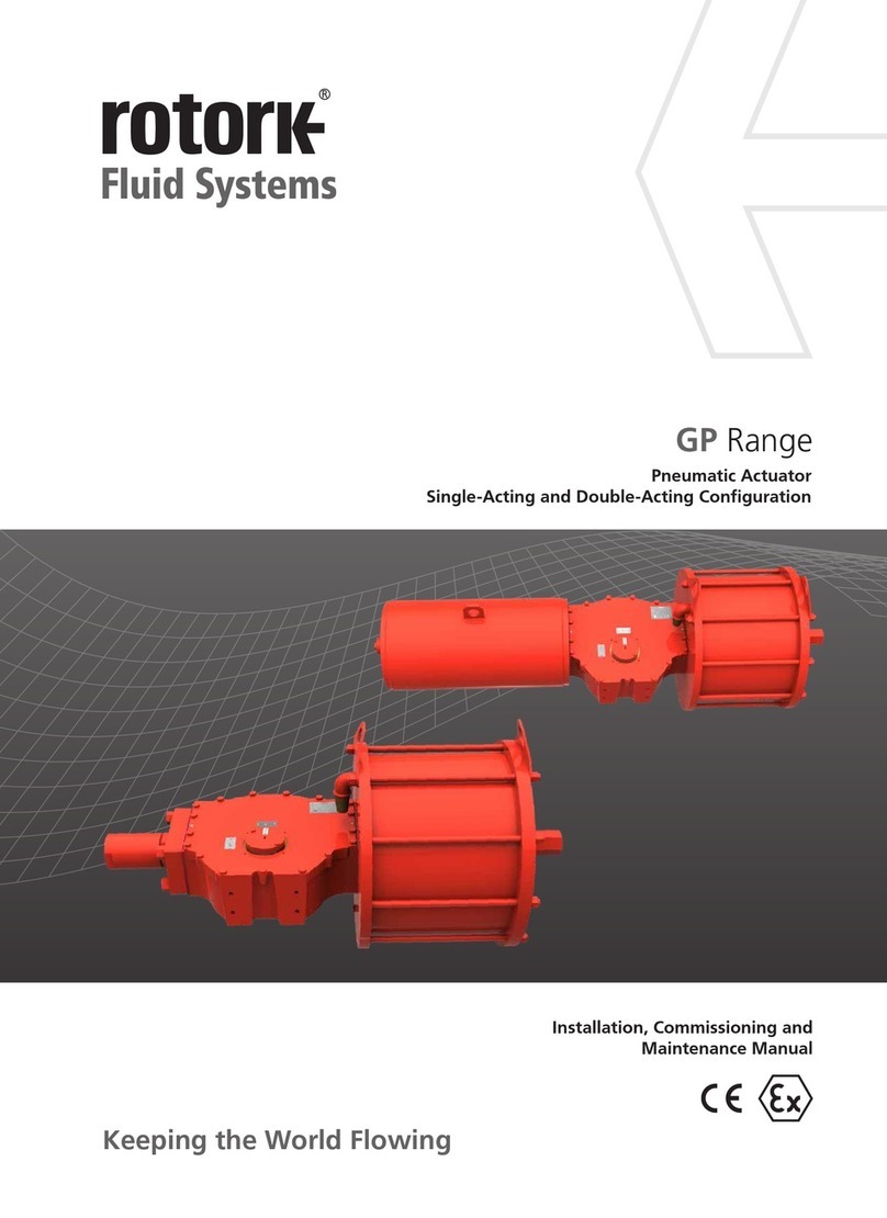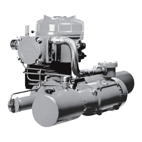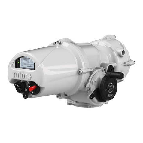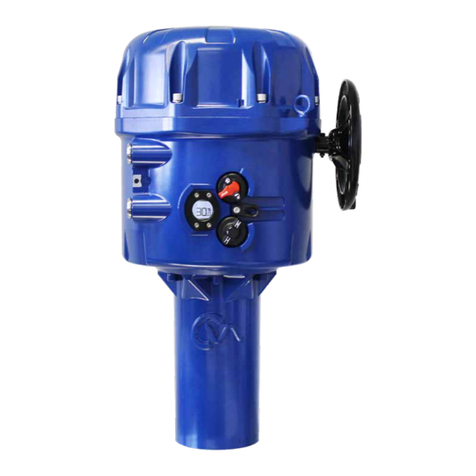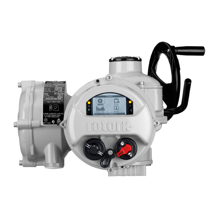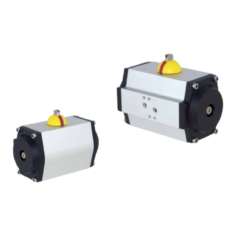
RH Range Installation, Commissioning and Maintenance Manual
4
3. General Information
This manual is produced to enable a competent user to install,
operate and maintain Rotork RH single and double-acting
actuators.
The mechanical installation must be carried out as outlined
in this manual and in accordance with any relevant national
standard codes of practice.
Maintenance and operation must be carried out in
accordance with the National Legislation and Statutory
Provisions relating to the safe use of this equipment,
applicable to the site of installation.
Any inspection or repair in a Hazardous Area must not be
undertaken unless it conforms to National Legislation and
Statutory Provisions relating to the specific Hazardous Area.
Only Rotork approved replacement parts should be used.
Under no circumstances should any modification or alteration
be carried out on the equipment, as this could invalidate the
conditions under which certification was granted.
Only trained and experienced operators can install, maintain
and repair Rotork Actuators. Work undertaken must be
carried out in accordance with instructions in this manual.
The user and those persons working on this equipment
must be familiar with their responsibilities under any
statutory provisions relating to the Health and Safety of their
workplace.
Operators must always wear appropriate Personal Protection
Equipment (PPE) in line with the existing plant regulations.
Appropriate usage
Rotork RH range actuators have been specifically developed
to motorize ¼ turn valves, such as ball valves, butterfly valves
or plug valves installed on pipelines for oil & gas transport
and distribution.
Improper use can damage the equipment or cause
dangerous situations for health and safety. Rotork
declines any responsibility for damage to people and/
or objects resulting from the use of the equipment
for applications different from those described in the
present manual.
Before installing the equipment, verify it is suitable for the
intended application. If unsure consult Rotork.
4.1 Residual Risks
Residual risks resulting from equipment risk evaluation
performed by Rotork.
4.2 Thermal Risks
Risk
Hot/Cold surface during normal operation.
Preventive measures
Operators should wear protective gloves.
4.3 Noise
Risk
Noise >85 dB during operation.
Preventive measures Operators must wear ear protections.
Operators must not stand near the
equipment during operation.
4.4 Health Risks
Risk Pressurized fluid ejection during
normal operation.
Preventive measures All fittings must be properly sealed.
All fixing clamps must be correctly
tightened and sealed.
Risk Risk of intoxication (per the type of
medium utilized).
Preventive measures Operators must use P.P.D.s and any
other equipment (breathing apparatus)
based on the type of supply medium.
4.5 Mechanical Risks
Risk Uncontrolled movement (remote
operation). (This risk is applicable
only for actuators provided with
control panel).
Preventive measures
Assure that the actuator cannot be
operated remotely. Prior to starting,
remove Hydraulic supply, vent all pressure
vessels, and remove electrical power.
Risk Presence of moving parts (centre body,
valve adapter).
Preventive measures
Do not perform start-up or test the
actuator if the cylinder tube is removed.
Risk Loss of stability with possible parts
projection.
Preventive measures Do not disassemble the actuator
in case of malfunctioning. Follow
instructions in the present manual and
contact Rotork.
Preventive measures Foresee periodic maintenance
procedure to verify tightening.
4. Health & Safety
A4US
US
A4
US A4
US
A4
