Bentel KYO 32 M User manual

KYO
Unit
USER
MANUAL
®
MADE
IN
ITALY

®®
BENTEL SECURITY srl reserves the right to modify the technical specifications of this product without prior notice.
KYO 4 M – KYO 8 M – KYO 32 M – KYO 4 P – KYO 8 P – KYO 32 P
KYO 8G P-SW1 – KYO 8G P-SW2 – KYO 32G P-SW1 – KYO 32G P-SW2
Hereby, Bentel Security, declares that the above mentioned Control Panels are in compliance with the essential
requirements and other relevant provisions of Directive 1999/5/EC.
The complete R&TTE Declaration of Conformity for each Panel can be found at
www.bentelsecurity.com/dc.html.
These Control Panels comply with CEI 79-2 2aed. 1993.
Installation of these systems must be carried out strictly in accordance with the instructions
described in this manual, and in compliance with the local laws and bylaws in force.
The above mentioned Control panels have been designed and made
to the highest standards of quality and performance.
The manufacturer recommends that the installed system should be completely tested at least once a month.
BENTEL SECURITY Srl shall not assume the responsibility
for damage arising from improper application or use.
The above mentioned Control panels have no user-friendly components, therefore,
should be serviced by authorized personnel only.

3
®®
TABLE OF CONTENTS
Introduction .............................................................. 5
The Control Panel .................................................................. 5
Glossary ................................................................................. 7
Operating from a Keypad ......................................... 8
Introduction .................................................................................... 8
Keypads .................................................................................. 8
LED Keypads (NC2/TAST and ICON/KP) ....................................... 9
Real-time signals .................................................................. 9
‘View Trouble’ mode .............................................................. 10
‘View Partition Status’ mode .................................................. 11
LCD Keypads (OMNIA/TAST-R and MIA) ....................................... 12
Volume Adjustment (MIA only) ............................................... 12
Contrast Adjustment (MIA only) ............................................. 13
Brightness Adjustment (MIA only) ......................................... 13
Viewing Troubles .................................................................... 14
Viewing Trouble Details (KYO 32 Series only) ..................... 14
Buzzer ............................................................................................. 15
Superkeys ...................................................................................... 15
Basic Operations ........................................................................... 16
Global Arming (Code + O) ..................................................... 16
Global Disarming (Code + o) ............................................... 17
A or B Mode Arming (Code + Aor Code + B) ...................... 17
Notes on Arming from Keypads ............................................ 18
Silencing Alarm Devices from Keypads ................................ 18
Wrong Code ........................................................................... 18
User Menu and Main User Menu .................................................. 19
Reset Alarm or Clear Alarm Memory ..................................... 20
Arming and Disarming your System ..................................... 21
Overtime Request .................................................................. 22
Teleservice Request .............................................................. 23
Turning ON your System Automatically ................................. 24
Turning ON Teleservice ......................................................... 25
Enable/Disable Buzzer ........................................................... 26
Enable/Disable Answer Function (KYO 32 Series only) ...... 27
Output Control (KYO 32 Series only) ..................................... 27
Programming Telephone Numbers ...................................... 28
Programming Codes ............................................................. 29
Programming the Date and Time ......................................... 30
Test Siren................................................................................ 31
Zones Status .......................................................................... 32
View Logger ............................................................................ 33
Clear Call Queue .................................................................... 34

4Multifunction Control Panel
®®
Using Digital Keys and Cards ................................. 35
Introduction .................................................................................... 35
Readers.................................................................................. 35
Digital Keys/Cards ................................................................. 36
The Reader LEDs ........................................................................... 37
No Key/Card at Reader .......................................................... 37
Key/Card at Reader ................................................................ 37
The PROXI Buzzer ......................................................................... 38
Multiple Systems ........................................................................... 38
Digital Key/Card operations .......................................................... 38
Disarm (Turning OFF your system) ....................................... 38
Arm — Global Mode (Turning ON your system) .................... 39
Arm — A Mode ........................................................................ 39
Arm — B Mode ........................................................................ 40
Silencing Alarm Signalling Devices from ECLIPSE Readers 40
Inhibit Alarms (Service Mode) ................................................ 40
Operating the System from a Telephone ................ 42
Remote Telephone Access via ‘Dialler’ mode ............................ 42
Remote Telephone Access via ‘Answer’ mode .......................... 42
Teleservice Enabled .............................................................. 43
Teleservice Disabled ............................................................. 43
Entering Your Telephone Access Code (DTMF) .......................... 43
Entering Commands ..................................................................... 44
Cancel Command .................................................................. 44
Stop Alarm / On Hook ............................................................. 44
Remote Talk / Listen-in .......................................................... 44
Remote 2Way Talk / Listen-in ................................................ 44
Turning Appliances ON/OFF (Reserved Outputs) ................ 44
Arm / Disarm .......................................................................... 45
Enable / Disable Telephone Access Code ........................... 45
The Wireless Key ...................................................... 46
Introduction .................................................................................... 46
Using the Wireless key ................................................................. 46
Global Mode ........................................................................... 46
Disarm Global ........................................................................ 46
A Mode Arming ....................................................................... 47
B Mode Arming or Superkey 2 ............................................... 47

5
®®
Introduction
INTRODUCTION
The Control Panel
This Manual is designed for anyone using a Control panel from the KYO range.
Most of the features described in this Manual are included on all KYO Control
panels. However, some features are included on certain models only, in such
cases, the name of the Control panel will be specified.
Your Installer has set up your system with your premises in mind. You may not
need all the features descibed in this Manual, therefore, your Installer will have
programmed only the features you need.
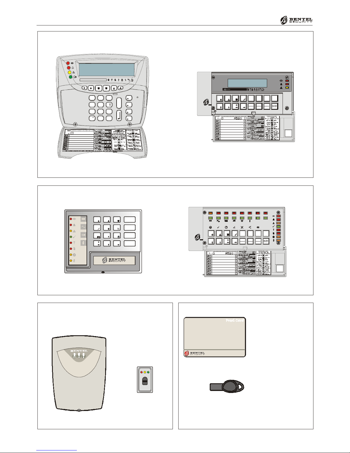
The functions on KYO4 and KYO8 (4 Partition Control panels) and KYO32 (8
Partition Control panel) can be controlled from Keypads and Digital Readers
(see Figures 1, 2, 3 and 4).
This Manual provides step-by-step instructions for each function.
This Control panel has an intergrated Digital Communicator, that allows your
system to send Alarm, Trouble and Emergency messages to the Central Station,
This feature also allows your Installer to carry out remote maintenance (Teleser-
vice).
If your system is equipped with an NC2/VOX Voice board (accessory item),
your Digital communicator will be able to send voice messages.
Series 32 Control panels accept Vector/RX Receivers. Installation of a Vector/
RX Receiver will allow the control panel to manage Wireless security devices
(Detectors, Magnetic Contacts, etc.) and Wireless Keys.
Read this guide thoroughly to learn how to use your system. See the Glossary to
learn about the words used in the instructions.
About Your Security
System
Controlling Your
System
The Digital
Communicator
The NC2/VOX Voice
Board
The Vector/RX
Wireless Receiver
(for KYO Series 32)
6Multifunction Control Panel
®®
#
345678
0AB
EXC
ESC
12
9
PRG
ON
RES
OFF
135 72468
OMNIA/TAST-R
#
D5.0 BNML OGO P.1 2804 99
D5.0 NN MLED P.1 280499
®
ON
OFF
ESC
ENTER
1
4
7
A
2
5
8
0
3
6
9
B
#
345678
0AB
EXC
ESC
12
9
PRG
ON
RES
OFF
87654321
NC2/TAST ICON/KP
PROXI-READER
ECLIPSE
®
PROXY-CARD
SAT KEY
2
abc
3
def
1
5
jkl
6
4
ghi
8
tuv
9
7
pq
rs
0
A
#
B
C
D
E
S
C
wx
yz
OFFON
135724 68
MIA-S MIA-D
Figure 1 - LCD Keypad
Figure 2 - LED Keypad
Figure 3 - Readers Figure 4 - Digital Key

7
®®
Introduction
Glossary
A limited area of the premises monitored by detectors (e.g. Motion detectors,
Door/Window contacts, etc.).
A peripheral device connected to the Control panel by a 4 pin conductor.
An audible signalling device inside Keypads and PROXI Readers.
If remote monitoring is enabled, your system will send Alarm, Trouble and
Emergency messages to the Central station.
A device that signals alarm conditions (e.g. Glassbreak, Forced entry, etc.).
An optional device that sends voice message to programmed phone numbers.
An integrated on-line device that sends digital signals.
An electronic control key (see Figure 4) with a random code (selected from over
4 billion combinations).
An alphanumeric screen on the LCD Keypads.
A command keypad with a display. Your Control panel can be programmed and
controlled via LCD Keypads.
A small coloured light on the Keypads and Readers.
A command keypad with LEDs. Your Control panel can be controlled via LED
Keypads.
A list of the last 256 events on Series 32 Models.
A list of the last 128 events on Series 4-8 Models.
A part of the premises. Each Partition can have its own Times, Code PINs
and Digital Keys/Cards, etc.
A peripheral control device (see Figure 3) that accepts commands from Digital
Keys/Cards (e.g. PROXI Proximity Reader, ECLIPSE Readers).
Instant Audible/Visual signals or communications.
A remote-monitoring service provided by a Central Station. This feature will
allow the Control panel to transmit real-time events (e.g. Forced entry, Tamper,
Alarms, etc.) to the Central station.
Remote maintenance provided by your Installer. The Teleservice feature allows
the Installer to operate on your system over the phone.
Alarm Zone
BPI Device
Buzzer
Central Station
Detector
Dialler
Digital
Communicator
Digital Key
Display
LCD Keypad
LED
LED Keypad
Logger
Partition
Reader
Real-time
Telemonitoring
Teleservice
8Multifunction Control Panel
®®
OPERATING FROM AKEYPAD
Introduction
Keypads
This Control panel accepts LCD Keypads — OMNIA/TAST-R, MIA-S and
MIA-D (see Figure 1), and LED Keypads — NC2/TAST and ICON/KP (see
Figure 2).
The instructions in this guide show the keys of the NC2/TAST and ICON/KP
Keypads. The equivalent keys on the OMNIA/TAST and MIA can be seen in
Table 1 (below). Please note that some keys perform different operations in
accordance with their status (Normal or Superkey status).
NOTE: The set of commands provided by LED Keypads depends on the
Control panel series (Series 32 or Series 4 and 8). Therefore, the Control panel
Series will be indicated by Ì,Ðor èwhen operations are available.
Table 1 - KEY Equivalence
KEY NC2/TAST ICON/KP OMNIA/TAST-R MIA-S or MIA-D
1 ... 9 1... 91... 91... 91... 9
00000
A AAAA
B BBBB
ESC (Escape) eeee
ON OOOO
OFF oooo
ENTER EEEE
Cursor !AAAA
Cursor "BBBB
Cursor #888C
Cursor $000D
Superkey 1 1
for 3 seconds 1
for 3 seconds 1
for 3 seconds Ì+ Í
Superkey 2 2
for 3 seconds 2
for 3 seconds 2
for 3 seconds P+ p
Superkey 3 3
for 3 seconds 3
for 3 seconds 3
for 3 seconds À+ Á
ÌÐè

9
®®
Operating from a Keypad
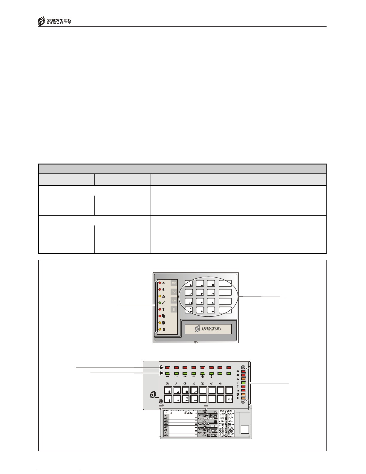
LED Keypads have lights and/or backlighted keys (see Figure 5) that will turn
ON or blink to indicate specific conditions. The LED Keypads can be used for
system control only.
Real-time signals
Table 2 shows the meaning of the real-time signals on the Keypad LEDs.
Table 2 - Real-time signals on LED Keypads
NC2/
TAST
ICON/
KP DESCRIPTION
Red OFF - All the Keypad Partitions are Disabled
ON - At least one of the Keypad Partitions is Armed
II
Red OFF - No Alarms in Memory
Slow Blinking - At least one Alarm in Memory
Fast Blinking - Alarm in course
aa
Yellow OFF - No Trouble
ON - At least one Trouble condition is present: check system via 'View Trouble'
Slow Blinking - 'View Trouble' mode active
GG
Green
OFF - At least one Unbypassed Alarm Line is violated
ON - Ready to Arm: All the Unbypassed Alarm Lines are in Normal status
Fast Blinking - This will occur when:
a) The Control panel is in 'Test' status
b) A Digital Key in inserted into an ECLIPSE Reader
c) A Digital Key/Card is present at a PROXI Reader
VV
Red OFF - NoTamper
Slow Blinking - At least one Tamper condition in Memory
Fast Blinking - Tamper in course
TT
Red OFF - Control panel Closed
ON - Control panel Open
SS
Amber OFF -
All the zones of the Keypad Partitions are Unbypassed, and not in 'Test' status
ON- At least one of the zones of the Keypad Partitions is Bypassed
Slow Blinking - At least one zone is in 'Test' status
Fast Blinking - At least one zone is Unbypassed, and one in 'Test' status
XX
Amber OFF - The Teleservice option is Disabled
ON - The Teleservice option is Enabled
Slow Blinking - Programming in course
Fast Blinking - Access to the User menu
PP
Red Green OFF- Telephone Line disengaged
Fast Blinking - Telephone Line engaged
Key
0x
Red
OFF - Zone in 'Normal' status
Slow Blinking - The Zone has logged at least one violation (Alarm)
Fast Blinking - The Zone has been violated (refer to the 'Zones Status' section)
Keys 1 to 8
1
... 8
LEDs
g ... g
1 8
LED Keypads (NC2/TAST and ICON/KP)
ÌÐè
10 Multifunction Control Panel
®®
Table 4 - 'View Trouble' on LED Keypads
NC2/TAST ICON/KP Meaning
Amber Slow Blinking - 'View Trouble' mode active. Only the LED on the
keypad in use will blink
GG
Key
Red Green ON - indicates Blown fuse (the fuse protecting the power supply to
the detectors)
1F
Key
Red Green ON - indicates 220 V~
Mains failure
4R
Key
Red Green ON - indicates Low Battery, Battery Trouble or Blown Fuse
This type of Trouble will be signalled with a 4 minute delay
7L
Key
Red Green ON - indicates that all Codes are set at Factory Default
AD
Key
Red Green ON - indicates Telephone line Trouble (Line Down)
0x
Key
Red Green ON - BPI Trouble (e.g. one of the control or signalling devices is
out-of-service)
B/
‘View Trouble’ mode
Table 4 shows how the Keypad lights will signal the various Troubles.
Press EE
EE
Eto access the ‘View Trouble’ mode from ‘Normal’ status (Control
panel Armed or Disarmed)
Press ee
ee
eto exit the ‘View Trouble’ mode
The ‘View Trouble’ mode will exit automatically after 15 seconds of inactivity.
Exit will be confirmed by an audible signal (Buzz).
ÌÐ
11
®®
Operating from a Keypad
Figure 5 - Keypad LEDs
‘View Partition Status’ mode
Table 5 shows how the Keypad lights will signal the status of the Partition.
Press OO
OO
Oto access the ‘View Partition Status’ mode from ‘Normal’ status
(Control panel is Armed or Disarmed)
Press ee
ee
eto exit the ‘View Partition Status’ mode.
The ‘View Partition Status’ will exit automatically after 15 seconds of inactivity.
Exit will be confirmed by an audible signal (Buzz).
#
345678
0A B
EXC
ESC
12
9
PRG
ON
RES
OFF
87654321
System LEDs
Zones Status LEDs (1 ... 8)
Red
Trouble LEDs (1 ... 6)
Green
#
D5.0 BNMLOGO P. 1 2 8 0499
D5.0 NN MLE D P. 1 280499
®
ON
OFF
ESC
ENTER
1
4
7
A
2
5
8
0
3
6
9
B
System LEDs
Backlighted Keys
Table 5 - 'View Partition Status' on LED Keypads
NC2/TAST ICON/KP Meaning
Red
Fast blinking -- indicates 'View partition Status' active"
Key
OI
Red
OFF - Partition Disarmed
ON - Partition Armed
Keys 1 to 8
1
... 8
LEDs 1 to 8
g
... g
1 81
ÌÐ
12 Multifunction Control Panel
®®
LCD Keypads (OMNIA/TAST-R and MIA)
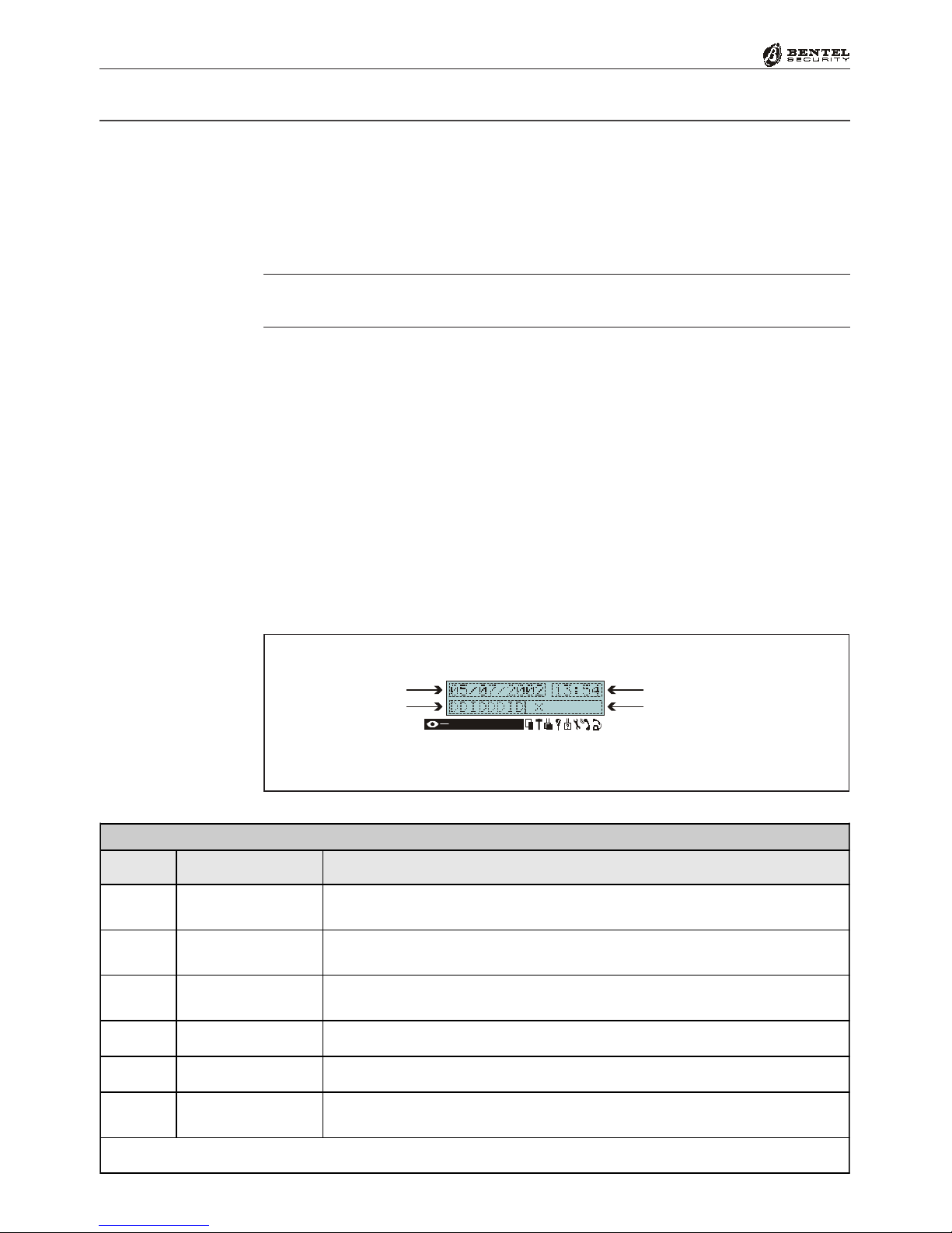
The keypad display (see Figure 6) will provide information on the system status.
During ‘Normal’ status, the top line of the display will show the Date and
Time, and the bottom line will show the Armed/Disarmed status of the Parti-
tions (refer to Table 6), and Trouble events and information regarding the
Control panel (refer to Table 7).
To view the Partition status, press OO
OO
O: the status of each Partition (and relative
descriptions) will be shown at 2 second intervals.
If the Control panel has Zone Alarm or Tamper in memory (LED aa
aa
ablinking),
the top line will show the zone description (Label).
If Tamper or Alarm conditions are present on more than one zone, the relative
zone descriptions will be shown every 2 seconds.
Table 7 shows how the LCD Keypad lights and display will signal the system
status in real-time.
Volume Adjustment (MIA only)
To adjust the volume: push ee
ee
eto activate the audible signals. Release the button
when the required volume is signalled.
13572468
Date
Partitions Status
Hour
Troubles, Tampers, Controls
Figure 6 - The display of LCD Keypads during Standby status
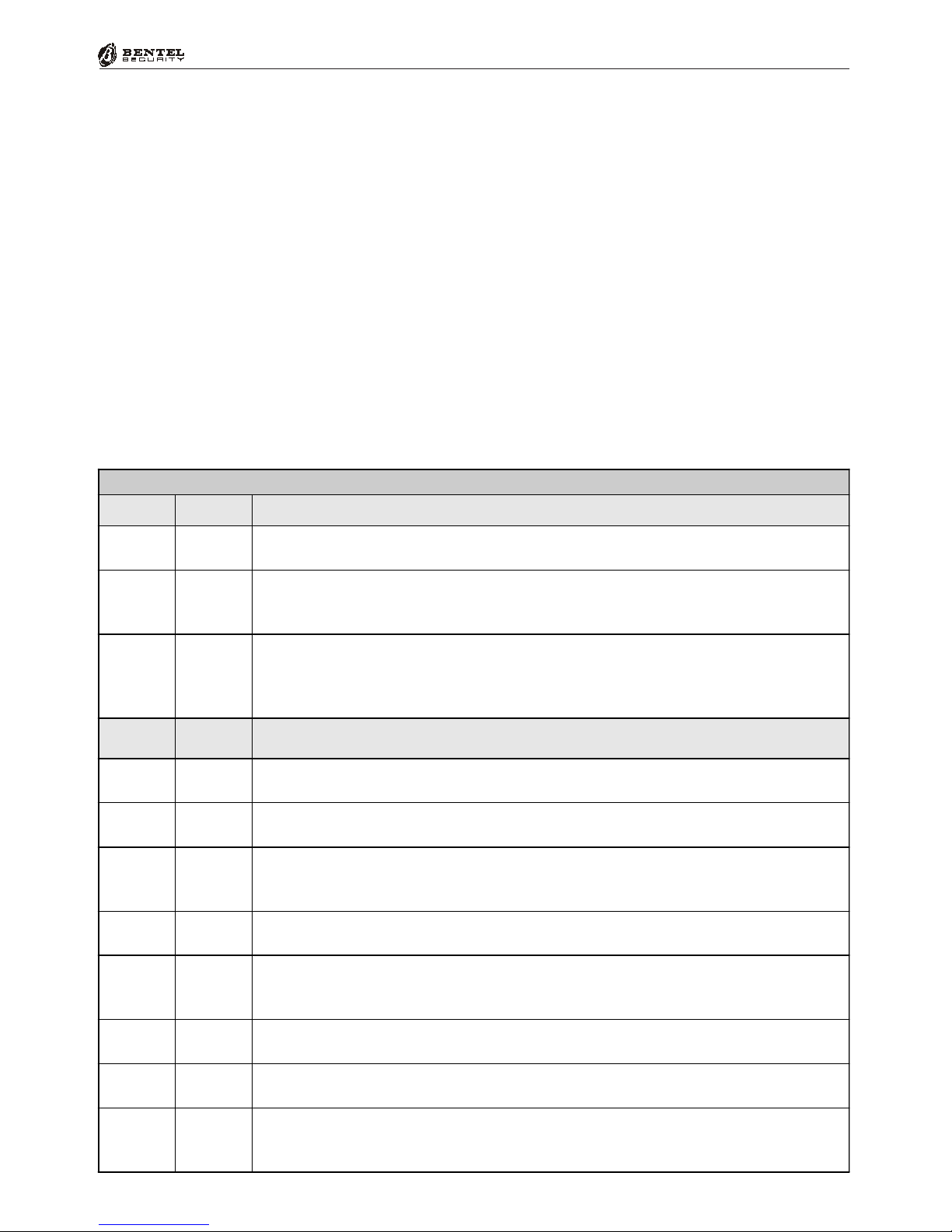
Table 6 - Arming/Disarming Partitions
Letter Mode Result
AAway The corresponding partition will be fully armed, and the system will
monitor all zones
SStay The corresponding partition will be partially armed, and the system will
bypass 'Stay' zones
IStay - 0 Delay The corresponding partition will be partially armed, and the system will
bypass 'Stay' zones and ignore the Partition Entry Time
DDisarm The corresponding partition will turn OFF
NNo Change The corresponding Partition will maintain its current status
-Disabled The corresponding partition is not a Keypad partition, therefore,
cannot be controlled from the keypad in question
N.B. If the Partition has already detected Alarm conditions, the letters will blink.
13
®®
Operating from a Keypad
Table 7 - Signals on LCD Keypads
Icon LED
I
Red
OFF - All Partitions Disarmed
ON - At least one Keypad Partition is Armed
a
Red
OFF- No Alarms in Memory
Slow Blinking - At least one Alarm In Memory
Fast Blinking - Alarm in course
G
Amber
OFF - No Trouble, No bypassed or Test zones
ON - At least one Trouble condition is present
Slow Blinking - At least one zone is Bypassed status or in Test status
Fast Blinking - At least one zone is in Trouble, and one is Bypassed or Test status
Icon Signalled
by MEANING
SûON - Control panel open
Blinking - At least one Open Panel event in Memory
TûON - Tamper in course
Blinking - At least one Tamper event in Memory
bû
ON - Tamper in course on at least one of the peripheral devices (Keypad,
Reader, Expander or Receiver)
Blinking - At least one Tamper event in Memory
fûON - A False Key/Card is present at a Reader
Blinking - At least one False Key/Card event in Memory
sû
ON - A peripheral device (Keypad, Reader, Wireless or Expander) has been
disconnected
Blinking - At least one Peripheral Trouble event in Memory
t*OFF - Teleservice Disabled
ON -Teleservice Enabled
r*OFF - Answerphone function is Disabled
ON- Answerphone function is Disabled
iÿ
OFF - Line Free
ON - Line Engaged
Blinking - Line Down
Volume signals :
%short low short beep "MUTE
%long low beep "MEDIUM Volume
%Long loud beep "MAXIMUM Volume
Contrast Adjustment (MIA only)
To adjust the LCD Contrast, press:
%CC
CC
Cto increase Contrast
%DD
DD
Dto decrease Contrast
Brightness Adjustment (MIA only)
To adjust the LCD Brightness, press:
%AA
AA
Ato increase Brightness
%BB
BB
Bto decrease Brightness
14 Multifunction Control Panel
®®
Viewing Troubles
If the amber GLED turns ON, it means that at least one trouble condition has
been detected. To view current (or stored) ‘Trouble’ details, access the Main
User Menu and select the View Logger option (refer to the ‘View Logger’
paragraph in this section).
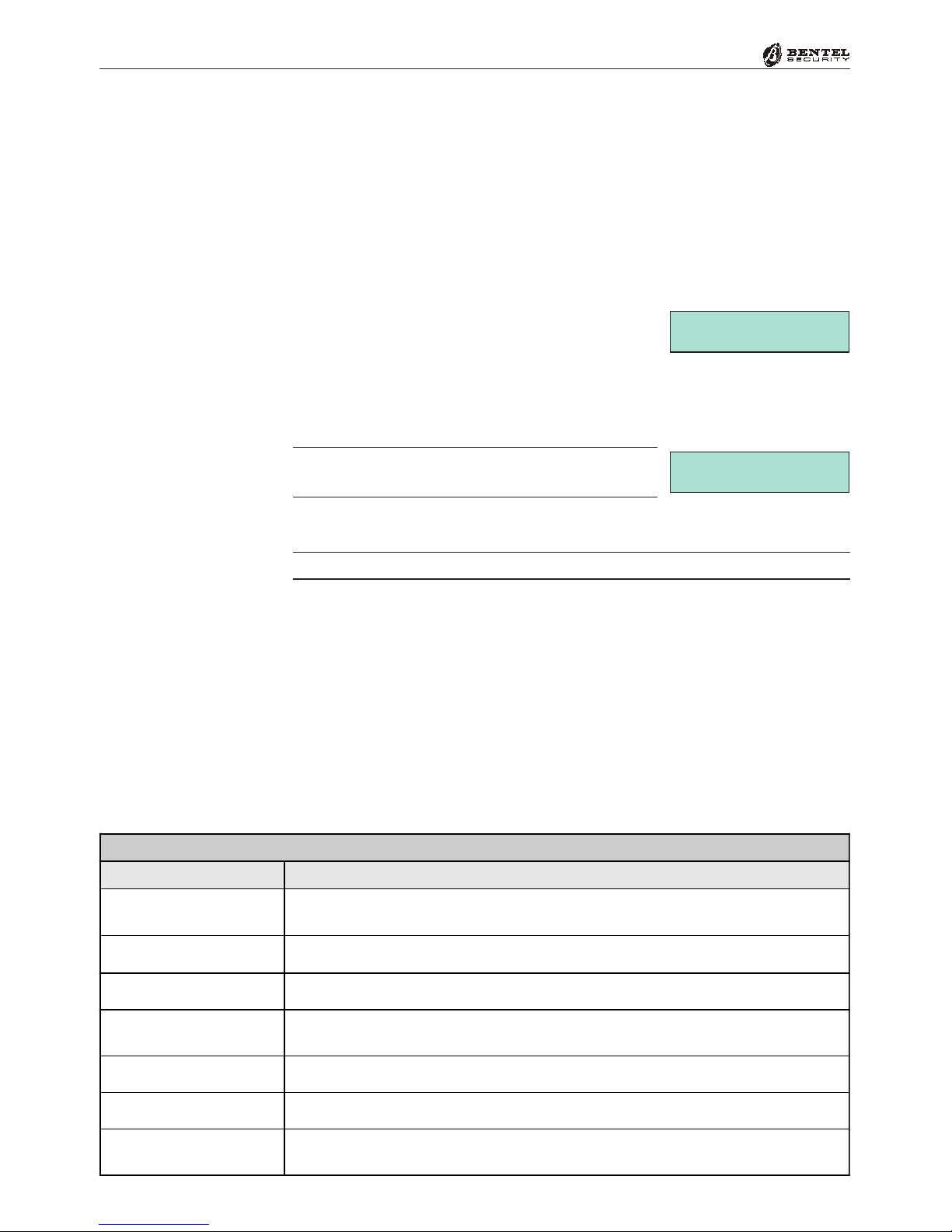
Viewing Trouble Details (KYO 32 Series only)
To view the details of current ‘Troubles’, proceed as follows:
1. From Standby status (regardless of whether the
system is Armed or Disarmed), press EE
EE
E.
2. The Trouble events will be shown on the second line of the display. Use 99
99
9
and 00
00
0to scroll the Troubles list. Refer to the ‘Viewing Trouble Details’
Table for the Troubles that the Control panel is able to detect.
If the Control panel is functioning properly, the
display will show the “No Troubles” message.
3. Press ee
ee
eto exit.
Automatic exit will occur after 30 seconds of Keypad inactivity.
Syst. Troublesáâ
Mains Fault
Syst. Troublesáâ
No Troubles
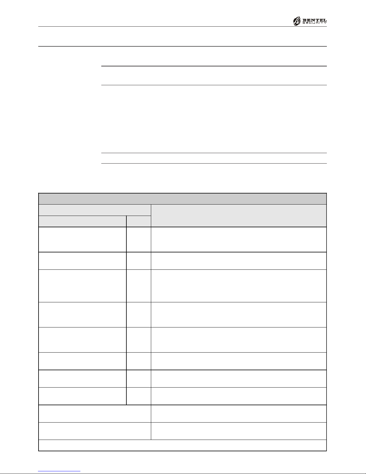
"Viewing Trouble Details" Table
Trouble Description
Mains Fault The Mains power supply to the Control panel has been cut off. If it is not a
general Black-Out—Contact your Installer
BPI Fault A BPI device has failed to respond (Missing device) —Contact your Installer
Fuse Fault Blown fuse—Contact your Installer
Battery Fault The Control panel battery is not recharging properly or is faulty —Contact
your Installer
Tel. Line Trouble Telephone Line problems —Contact your Installer
Default Codes This Trouble condition will be present until a User Code is programmed
WLS Fault For Wireless systems, the Wireless Receiver is not functioning properly
—Contact your Installer

15
®®
Operating from a Keypad
The Keypad Buzzer will emit an audible signal each time a valid key is pressed,
and will also signal:
%The Exit Time (signalled by slow beeps)
%The Entry Time (signalled by fast beeps)
%Errors or Invalid requests (signalled by a Buzz)
%Request Accepted or Done (long beep)
%Violation of a ‘Chime’ zone
Buzzer
Superkeys
If your Installer has set up the 3 Superkeys (refer to Table 1). You will be able to
operate your system from the keypad, without using Codes. The ‘Superkeys’
can activate the:
%Digital Communicator — transmits event codes to the Central Station
%Dialler — sends a voice message (requires NC2/VOX Voice board)
Up to 8 Telephone numbers can be programmed for these commands.
A long beep will confirm that the selected facility has been activated.
ÌÐè
ÌÐè
16 Multifunction Control Panel
®®
This section describes how to operate your system from a Keypad.
The operations at Keypads (refer to Table 8) will only affect the Partitions controlled
by the Code and Keypad in use.
The Factory Default User Codes must be changed for security reasons (refer to
‘Programming Codes’ in this section).
Global Arming (Code + OO
OO
O)
This command will Arm all the Partitions controlled by the Code and Keypad
in use.
If you are working from a LED Keypad, ensure that the Green LED
V
is ON.
To Arm the system in ‘Global’ mode — enter a Main User, User or Panic Code,
then press OO
OO
O.
Basic Operations
Changing User
Codes
Table 8 - Operations at Keypads
CODE+KEY Sequence OPERATION ALLOWED
Accepted Codes Key
<Main User Code>
<User Code>
<Panic Code>
OARM GLOBAL MODE Request
<Patrol Code> ORE-ARM Request (Only the Patrol Code that Disarmed the
Partitions will be allowed to Re-Arm them)
<Main User Code>
<User Code>
<Panic Code>
<Patrol Code>
oDISARM Request
<Main User Code>
<User Code>
<Panic Code>
AA MODE (System Partitioned)
<Main User Code>
<User Code>
<Panic Code>
BB MODE (System Partitioned)
<User Code>
<Panic Code> EAccess User Menu (Only for 'Alarm Reset','Overtime' and
'Enable/Disable Buzzer' Requests)
<Main User Code> EAccesses Main User Menu (All Options)
<Main User Code> eAccesses Bypass Zones Menu * (LED Keypads only)
OAllows Partition Status viewing
(for LCD Keypads only)
O
press and hold for 3 seconds Fast Arming
*
For LCD Keypads — this option is on the Main User Menu
"
Zones Status
ÌÐè

17
®®
Operating from a Keypad
If your Installer has enabled the Quick Arm feature, you will be able to Arm the
system from the keypad without using an Access Code, as follows:
1. Press and hold the OO
OO
Okey for 3 seconds.
2. Release the key after the audible signal (long beep), the system will Arm the
Keypad Partitions (as programmed by the Installer). This operation will
take about 2 seconds (the Keypad will emit an audible signal when the
system Arms).
Global Disarming (Code + oo
oo
o)
This command will Disarm all the Partitions controlled by the Code and
Keypad in use.
To Disarm the system in ‘Global’ mode — enter a Main User, User, Panic or
Duress Code, then press oo
oo
o.
The Duress code will disarm the system and trigger the Digital communicator. If
your Installer has set up your system to manage the Digital communicator facility,
the Digital communicator will send a voice message to the Central Station.
If the system is disarmed by a ‘Duress’ code, the keypads will remain mute.
A or B Mode Arming (Code + AA
AA
Aor Code + BB
BB
B)
This command will Arm/Disarm the Partitions controlled by the Code in use.
During the Programming phase, the User Codes will be configured for Stay/
Away arming (A or B Mode). The programmed configuration determines the
Partitions that will Arm/Disarm when you make an A or B Mode Arming re-
quest.
To Arm the system in A or B Mode — enter a Main User, User or Panic Code,
then press AA
AA
A(A Mode) or BB
BB
B(B Mode).
If your Installer has enabled the Quick Arm feature, you will be able to Arm the
system in A or B Mode from the keypad without using an Access Code, as
follows:
1. Press and hold the OO
OO
Okey for 3 seconds.
2. Release the key after the audible signal (long beep), press AA
AA
Aor BB
BB
B(A or B
Mode), as required.
If you do not press AA
AA
Aor BB
BB
Bwithin 2 seconds, the system will Arm the
Keypad Partitions (as programmed by the Installer).
Example: A Mode Arming configuration = Arm Partitions 1 and 4; Disarm
Partitions 2 and 3.
Quick Arm:
Aor B Mode
Disarm under Duress
Quick Arm
ÌÐè
ÌÐè
18 Multifunction Control Panel
®®
Notes on Arming from Keypads
Before your system Arms, your Control panel will check for the following
conditions:
%Violated Zones (Zones in Alarm status)
%Bypassed Zones (Zones that have been turned OFF)
If you are operating from an LED Keypad, these conditions will be signalled in
real-time on the Xand Vicons (refer to Table 2).
If you are operating from an LCD Keypad, these conditions will be signalled in
real-time on the display.
If Alarm conditions are signalled, DO NOT turn ON your system, as this will
trigger an Alarm.
The example (on the right) shows Zone 2 as Bypassed
(OFF) and Zone 4 in Alarm status (Violated).
If Alarms are signalled — press ee
ee
eto cancel the Ar-
ming request.
% Close all doors and windows, and stop all motion in the areas (partitions)
with motion detectors.
If Zones have been Bypassed unintentionally — press ee
ee
eto cancel the Arming
request.
% Access the User Menu, select the ‘Zone status’ option and Unbypass (turn
ON) the unintentionally Bypassed zones.
If your Installer has enabled your system, you can view Violated Zones (Zones
in Alarm status) on the display even when the system is Disarmed.
Silencing Alarm Devices from Keypads
The quickest way to silence Alarm Signalling Devices (Sirens and Flashers) is to
Disarm the system.
IMPORTANT - This operation will not interrupt the ongoing Alarm call, or
end the Alarm call cycle. Therefore, it will be necessary access the User Menu
(access allowed to Main User PINs only), and stop the Alarm calls, via the
‘Clear Call Queue’ option.
Tamper events, that occur when the system is disarmed, can be silenced via the
‘Reset Alarm’ option from the User Menu (access allowed to Main and User PINs).
For further information, refer to ‘Silence Alarm Signalling Devices from Reader’
paragraph in the ‘Using Digital Keys/Cards’ section.
Wrong Code
If a wrong code is entered, the Keypad will emit an
error signal (Buzz), and the display will show an error
message.
WRONG CODE
LED Keypads
LCD Keypads
Zone 2
BypassedNormal å
Zone 4
Unbypas.Alarm å
Clear Call Queue
Silence Tamper
Alarms

19
®®
Operating from a Keypad
The display strings in the examples in this section refer to Control panels with
8 Partitions (KYO32 and KYO32G). The display strings in other models from
the KYO range may be slightly different.
Enter a User or Main User Code then press EE
EE
Eto
access the Menu (refer to Table 8). The menu will
allow you to operate the Control panel in accordance
with the your access level (Main User Code or User Code). If you are using an
LCD Keypad, the display will show a short ‘WELCOME’ message.
You can access the Menu even when the Control panel is armed.
The Main User Menu provides the following options:
' Reset Alarm or Clear Alarm Memory
'Arm/Disarm
'Overtime Request
'Teleservice Request
'Enable/Disable Auto-Arm
'Enable/Disable Teleservice
'Enable/Disable Keypad Buzzer
'Enable/Disable Answer Function (KYO 32 Series only)
'Output Control (KYO 32 Series only)
'Program Telephone Numbers
'Program Codes
'Program Date/Time
'Test Siren
'Zones Status
'View Logger
'Clear Call Queue
When operating from an LCD Keypad, use keys 99
99
9and 00
00
0to scroll the Menu,
and EE
EE
Eto select the required option. When operating from an LED Keypad,
you will need to enter your access Code and press the command keys.
Press ee
ee
eonce or twice as required (depending on the Menu) to Exit the Menu
(in some cases ‘Exit’ is automatic).
‘User’ and ‘Panic’ Codes can access the User Menu (refer to Table 8) to make
‘Clear Alarm Memory’, ‘Overtime’ and ‘Enable/Disable Buzzer’ requests.
‘Patrol’ and ‘DTMF’ Codes cannot access the User Menu.
The following paragraphs describe the Main User Menu Options.
User Menu and Main User Menu
WELCOME
User Code 1
Accessing theMenu
Selecting the options
Exit the Menu
Limitations

20 Multifunction Control Panel
®®
Table 9a - Reset Alarm and Clear Alarm Memory options (Series 32)
Reset
Zone Alarm
Reset
Zone Alarm
Memory
Reset
Zone Tamper
Alarm
Reset Zone
Tamper Alarm
Memory
Reset System
Tamper Alarm
Reset
System
Tamper Alarm
Memory
Control panel (System) Armed
YES * or
Disarm
System
YES
YES or
Disarm
System
YES YES * YES
Control panel (System) Disarmed
- YES YES YES YES * YES
*- The Alarm Memories will reset automatically.
Reset Alarm or Clear Alarm Memory
The ‘Reset Alarm’ and ‘Clear Alarm Mem.’ options depend on the system
status.
If the system is in Alarm status the Menu will provide the ‘Reset Alarm’
option. This option will allow you to stop the audible and visual signalling
devices (Sirens, Flashers, etc.).
If the system is in Normal status the Menu will provide the ‘Clear Alarm
Mem.’ option. This option will allow you to clear the Alarm messages from the
Keypad display, or turn OFF the Keypad lights.
To Reset an Alarm, or Clear the Alarm Memory from an LCD Keypad, proceed
as follows:
1. From the User Menu, using 00
00
0or 99
99
9, scroll the
Menu for the Reset Alarm or Clear Alarm
Mem. option, as required.
2. Press EE
EE
Eto Reset Alarm / Clear Alarm Mem.,
as required. Acceptance of the command will be
confirmed by a beep and a short message.
To Reset an Alarm or Clear the Alarm Memory (for Control panels from the
KYO 4-8 series), from an LED Keypad, proceed as follows:
1. Access the User Menu.
Code PIN + EE
EE
E
The Pindicator will blink.
2. Press 00
00
0to Reset Alarm / Clear Alarm Mem., as required, or ee
ee
eto
cancel the request and, in both cases, Exit the Menu.
To Reset an Alarm or Clear the Alarm Memory from a LED Keypad for Control
panels from the KYO 32 series, enter a valid Code then press EE
EE
E.
Tables 9a and 9b indicate when and how you will be able perform Reset on KYO
32 and KYO 4-8 Series Control panels.
USER MENU áâ
Clear Alarm Mem.
Clear Alarm Mem.
Operation done
LCD Keypads
USER MENU áâ
Reset Alarm
LED Keypads ÌÐ
LED Keypads è
Other manuals for KYO 32 M
1
This manual suits for next models
9
Table of contents
Other Bentel Control Unit manuals


