3 Installation - continued
Figure 2. Mounting valve to base (Plug-in type)
3.8 Electrical circuits Caution
Surge suppression should be specified by using the appropriate part
number. If a valve type without suppression (Type ‘Nil’) is used,
suppression must be provided by the host controller as close as possible
to the valve.
3.8.1 Body ported VFS1000/2000/3000 and base mounted VFS2000
3.8.1.1 AC and 100 VDC (All types other than Grommet ‘G’)
Figure 3. Circuit diagrams - AC and 100 VDC
3.8.1.2 24 VDC or less (All types other than Grommet ‘G’)
Figure 4. Circuit diagram - 24 VDC or less
3.8.1.3 Grommet (Type G)
Figure 5. Circuit diagrams –Grommet
3 Installation - continued
3.8.2 Base mounted VFS3000/4000/5000/6000
3.8.2.1 Plug-in (conduit terminal)/Grommet terminal
100 VAC/DC or more 24 VDC or less
Figure 6. Plug-in circuit diagrams
3.8.2.2 DIN terminal (100 VAC/DC or more)
Figure 7. DIN circuit diagrams (100 VAC/DC or more)
3.8.2.3 DIN terminal (24 VDC or less)
Figure 8. DIN circuit diagrams (24 VDC or less)
3.9 Electrical connections Caution
Refer to specific product precautions in catalogue for how to change
direction of electrical entry and manual override (VFS1000 only).
3.9.1 Body ported VFS1000/2000/3000 and base mounted VFS2000 -
DIN terminal, Grommet terminal, Conduit Terminal
•Refer to specific product precautions in catalogue for how to change
direction of DIN terminal.
•Applicable heavy-duty cord O.D. ø6 mm to ø8 mm.
•Tightening torque for terminal: 0.6 N·m.
3.9.2 Grommet
Refer to 3.8.1.3 for Grommet wiring.
3 Installation - continued
3.9.3 Base mounted VFS3000/4000/5000/6000 - DIN terminal
Note: there is no polarity.
Figure 10. DIN terminal pin diagram
•Applicable cable: heavy-duty cord O. D.: ø8 to ø10.
•The following three crimped terminals are applicable to the terminal
block: 1.25Y-3L, 1.25-3.5S, 1.25-4M.
•Connector /Clamping torque: set screw 0.6 N·m, terminal screw 0.6
N·m.
•Incorrect common (DIN terminal no. 3) causes damage on power side
circuit.
3.9.4 Plug-in type (with terminal)
Caution
•Refer to figure 7: Removing junction cover (1) allows access to plug-in
terminal block (2). Connect with power side corresponding to
markings.
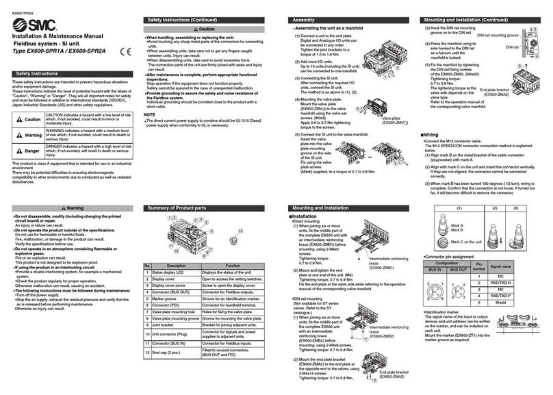
Figure 11. Plug-in (conduit terminal) electrical connection
Table 9.
•Applicable terminal :
VFS2000/3000 : 1.25-3, 1.25-3S, 1.25Y-3N, 1.25Y-3S.
VFS4000 : 1.25-3.5M, 1.25Y-3L, 1.25Y-3M
VFS5000 : 1.25-4, 1,25-4M
VFS6000 :1.25-3.5M, 1.25Y-3L, 1.25-3M
•There is no polarity.
•When ground wiring and COM wiring are required, please specify
separately.
•Tightening torque for terminal: 0.6 N·m.
3.9.5 Plug-in type manifold Caution
Refer to specific product precautions in catalogue for how to wire plug-in
manifold (lead wire, terminal, circular connector or D-Sub connector
types).
3.9.6 Non plug-in type (with terminal)
Figure 12. Grommet terminal electrical connection
•Refer to figure 11, remove cover (1), terminal block (2) is attached to
the inside of the body.
•For a valve with indicator light and surge voltage suppressor, pull out
the light and surge voltage suppressor substrate (3) in a straight
direction before connecting wiring.
•Connect with the corresponding power side.
•There is no polarity.
3 Installation - continued
•Applicable terminal:
VFS3000 : 1.25-3, 1.25-3S, 1.25Y-3N, 1.25Y-3S
VFS4000/50000/6000 : 1.25-3.5M, 1.25Y-3L, 1.25Y-3M
•Tightening torque for terminal: 0.6 N·m.
•Tightening torque for cover mounting screws:
VFS3000/4000: 0.5~0.7N・m
VFS5000/6000: 0.8~1.0 N・m
3.10 Residual voltage Caution
•If a varistor voltage suppressor is used, the suppressor arrests the
back EMF voltage from the coil to a level in proportion to the rated
voltage.
•Ensure the transient voltage is within the specification of the host
controller.
•Contact SMC for the varistor residual voltage.
•In the case of a diode, the residual voltage is approximately 1 V.
•Valve response time is dependent on surge suppression method
selected.
3.11 Countermeasure for surge voltage
Caution
•At times of sudden interruption of the power supply, the energy stored
in a large inductive device may cause non-polar type valves in a de-
energised state to switch.
•When installing a breaker circuit to isolate the power, consider a valve
with polarity (with polarity protection diode), or install a surge
absorption diode across the output of the breaker.
3.12 Extended period of continuous energization
Warning
•If a valve will be continuously energized for an extended period of time,
the temperature of the valve will increase due to the heat generated by
the coil assembly. This will likely adversely affect the performance of
the valve and any nearby peripheral equipment. Therefore, if the valve
is to be energized for periods of longer than 30 minutes at a time or if
during the hours of operation the energized period per day is longer
than the de-energized period, we advise using a valve with
specifications of 0.4 W or lower valve, such as the SY series, or a valve
with a power-saving circuit.
3.13 Effect of back pressure when using a manifold
Warning
•Use caution whenvalves are used on a manifold, because an actuator
may malfunction due to back-pressure.
•Special caution must be taken when using 3 position exhaust centre
valve or when driving a single acting cylinder. To prevent a
malfunction, implement counter measures such as using a single EXH
spacer assembly or an individual exhaust manifold.
4 How to Order
Refer to catalogue for ‘How to Order’.
5 Outline Dimensions
Refer to catalogue for outline dimensions.
6 Maintenance
6.1 General maintenance Caution
•Not following proper maintenance procedures could cause the product
to malfunction and lead to equipment damage.
•If handled improperly, compressed air can be dangerous.
•Maintenance of pneumatic systems should be performed only by
qualified personnel.
•Before performing maintenance, turn off the power supply and besure
to cut off the supply pressure. Confirm that the air is released to
atmosphere.
•After installation and maintenance, apply operating pressure and
power to the equipment and perform appropriate functional and
leakage tests to make sure the equipment is installed correctly.
•If any electricalconnections are disturbed during maintenance, ensure
they are reconnected correctly and safety checks are carried out as
required to ensure continued compliance with applicable national
regulations.
•Do not make any modification to the product.
