Bentley EXP12 Datasheet
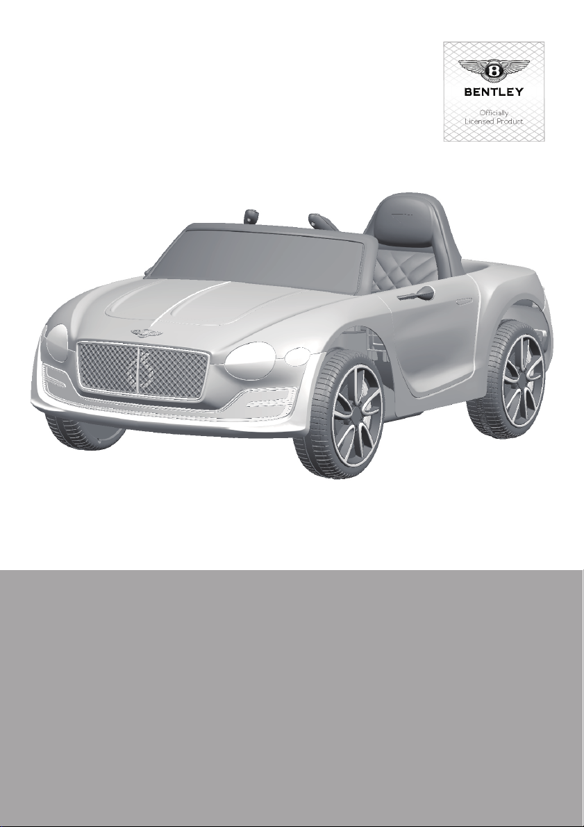
BENTLEY EXP12
Owner’s Manual
with Assembly Instructions
Styles and colo(u)rs may vary.
Made in China.
The owner’s manual contains important safety information as well as assembly, use and
maintenance instructions.
The Ride-on Car must be assembled by an adult who has read and understands the
instructions in this manual.
Keep the package away from children and dispose of properly before use.
Keep this manual for future reference.
Officially
Licensed Product
BATTERY OPERATED RIDE-ON

On the purchase of your new Bentley Ride-On.
This ride-on car will provide your child with many miles of riding of
enjoyment. To help assure you and your rider a safe ride we ask you to
please read this manual carefully, and keep it for future reference.
Follow the recommendations in this manual, they are designed to improve
the safety and operation of your ride-on car and it’s rider.
Battery
Charger
6V4Ah*1 or 6V7Ah*1
6V500mA or 6V1000mA
6V4Ah*2 or 6V7Ah*2
12V500mA or 12V1000mA
Suitable age:
Load Capacity:
Speed:
Size of car:
Power way:
Charge time:
37~96 Months
Under 30 kgs
1WD: 2.5 km/h 2WD:2.5~5 km/h
108*60*43 CM
Charging type
8 ~ 12 hours
About Your New Ride-On │ 1
VER: SMS-JJE1166-EN-190221
The Bentley Exp12 Battery operated Ride-On Manufactured by Zhejiang
Jiajia Ride-On Co., Ltd (Add: Xincang Industrial Zone, Pinghu City,
Zhejiang Province, P.R.China) under licence from Bentley Motors
Limited England. “Bentley”, the ‘B’ in wings device and other associated
logos and names are trademarks of Bentley Motors Limited. The body
designs of Bentley motor cars are protected by Bentley Motors Limited
under design, trademark and trade dress regulations.

1
2
3
4
5
6
7
8
9
10
11
12
13
14
15
16
17
18
19
20
1
1
1
3
3
8
1
4
4
4
2
1
2
1
1
1
1
2
1
1
2
2
2
2
6
2
8
PART
NO.
REMARKS
PART NAME
Q’ty (pcs)
Vehicle body
Gear box
Driving wheel
Normal wheel
Bush
Ø12 washer
Motor hood
Ø4x12 flat head screw
Lock nut
Hubcap
M5x16 machine screw
Seat
Mirror
Steering Wheel
M5x40 machine screw
Ø5 nut
Windshield
Spanner
Charger
Remote controller
Placed on the steering wheel
Placed on the steering wheel
Left and right
for seat
One labeled “L”, and the other one labeled “R”
1WD
2WD
2WD
Parts List │ 2
IF EQUIPPED, for R/C type only

19
20
18
13
14
1
7
3
2
6
9
9
10
10
6
4
8
12 11
17
15 16
6
5
22
23
21
HINT: Some parts shown are assembled on both sides of vehicle
Parts Diagram │ 3
CONTROLLER STYLES MAY VERY
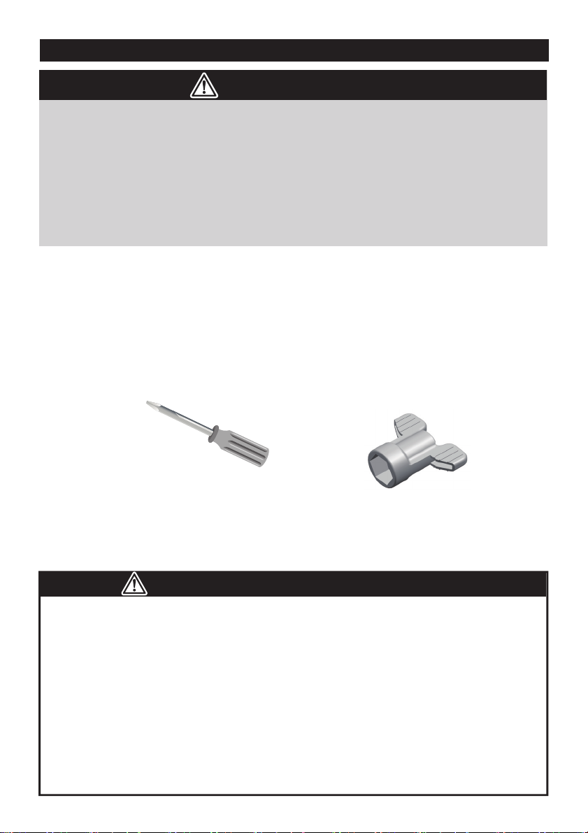
Before Assembly │ 4
• Make sure that the power switch is turned “OFF” before assembling the ride-on.
• Before first time use, charge the battery for at least 4 to 6 hours.
• Assembly tools required:
WARNING!
Screwdriver
(not included) Spanner
● Non-rechargeable batteries are not to be recharged.
● Rechargeable batteries are to be removed from the toy before being charged.
● Rechargeable batteries are only to be charged under adult supervision.
● Different types of batteries or new and used batteries are not to be mixed.
● Batteries are to be inserted with the correct polarity.
● Exhausted batteries are to be removed from the toy.
● The supply terminals are not to be short-circuited.
BATTERY INFORMATION
• CHOKING HAZARD - Small parts. Not suitable for children under 36
months. The product contains small parts, keep children away when
assembling.
• ADULT ASSEMBLY REQUIRED.
• Always remove protective material and poly bags and dispose before
assembly.
2
3
4
10
7
6
5
1
89
10
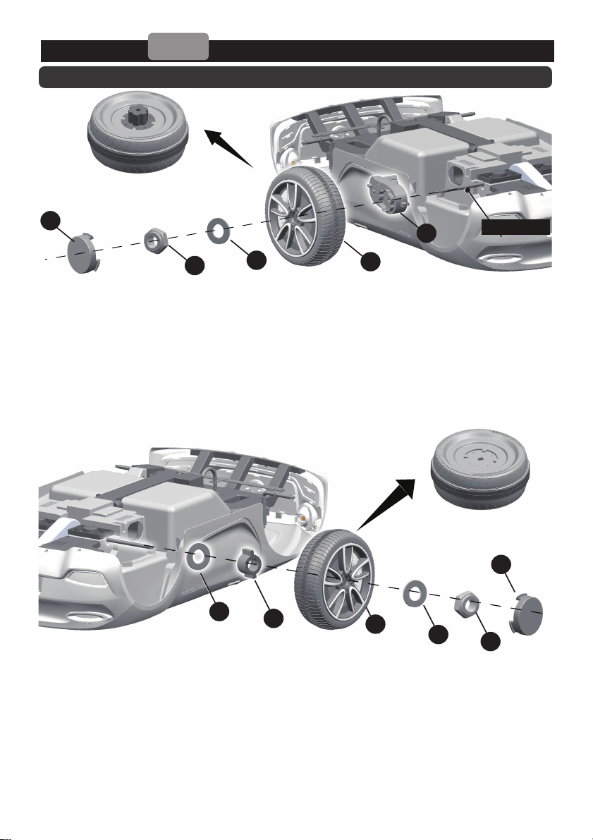
Attach the Rear Wheels │ 5
Driving Wheel
Normal Wheel
1WD
Rear axle
Rear Bottom View
1. Slide the gear box onto the rear axle (Left Side). Keep the motor and the
connector on the gear box through the larger hole on the rear of the vehicle
and out where the battery sits.
2. Slide the driving wheel onto the rear axle. And keep the driving wheel match
up with the gear box.
3. Slide the Ø10 washer onto the rear axle.
4. Tighten a lock nut to the end of the rear axle with a spanner.
5. Slide the Ø10 Washer onto the rear axle (Right Side).
6. Insert the bush into the hole in the center of the normal wheel.
7. Slide the normal wheel onto the rear axle.
8. Slide the Ø10 washer onto the rear axle.
9. Tighten a lock nut to the end of the rear axle with a spanner. HINT: An
extra spanner has been provided to hold the Lock Nut on the other side
of the rear axle while tightening the Lock Nut on the other side.
10. Fit the hubcaps to the wheels.
HINT: If your vehicle is Two Wheels Driving Type, see the next page please.

2
3
4
51
Attach the Rear Wheels │ 6
2WD
Driving Wheel
Rear axle
Rear Bottom View
1. Slide the gear box onto the rear axle. “R” labeled gear box should be fit to the
“R” side of vehicle body; “L” labeled gear box should be fit to “L” side of vehicle
body. Keep the motor and the connector on the gear box pass through the
larger hole on the rear of the vehicle and out where the battery sits.
2. Slide the driving wheel onto the rear axle. And keep the driving wheel match
up with the gear box.
3. Slide the Ø10 washer onto the rear axle.
4. Tighten a lock nut to the end of the rear axle with a spanner. HINT: An extra
spanner has been provided to hold the Lock Nut on the other side of the
rear axle while tightening the Lock Nut on the other side.
Repeat the above procedure to assemble the other driving wheel.
5. Fit the hubcaps to the wheel.
1
2
3
4
5
6
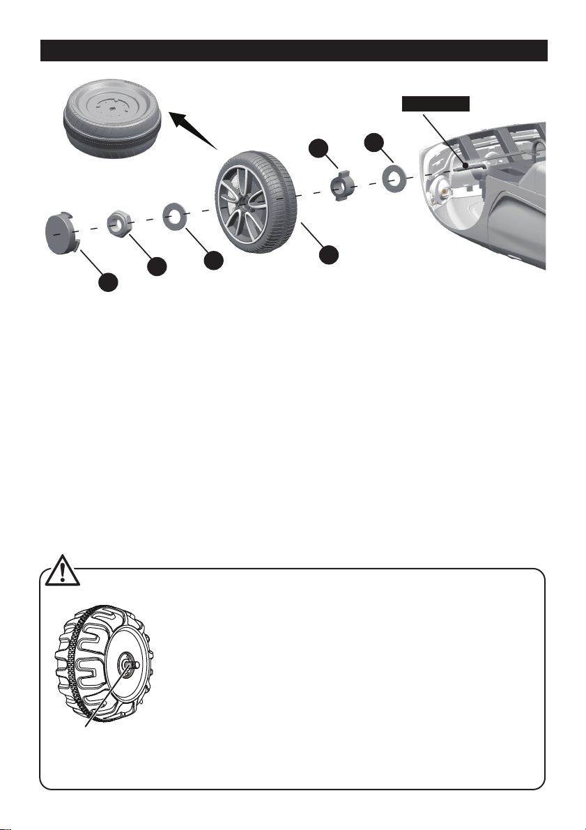
Front axle
Attach the Front Wheels │ 7
Normal Wheel
Front Bottom View
Remove all the parts from the front axle.
1. Slide a Ø10 washer onto the front axle.
2. Slide a bush into the hole in the center of the normal wheel.
3. Slide the normal wheel onto the front axle. And keep the normal wheel match up
with the bush.
4. Slide a Ø10 washer onto the front axle.
5. Tighten a lock nut to the end of the front axle with a spanner.
6. “Snap” the hubcap to the wheel.
Repeat the above procedure to assemble the other front wheel.
GAP
After assembling any wheel to the axles, please check the
gap between the screw thread and the collapsible (refer to
below picture), if the gap is too big, please add two or three
washers inside the wheel, but after tightening the nut outside
the wheel, please turn the wheel by your finger to check if the
wheel can run smoothly, this is very important, because if the
wheel can run smoothly, it is ok, but if the nut press the wheel
and the wheel can’t run smoothly, the motor will be broken
easily! Then you need to decrease one or two washers to
make sure the wheel can run smoothly!

24
1
6
7
3
5
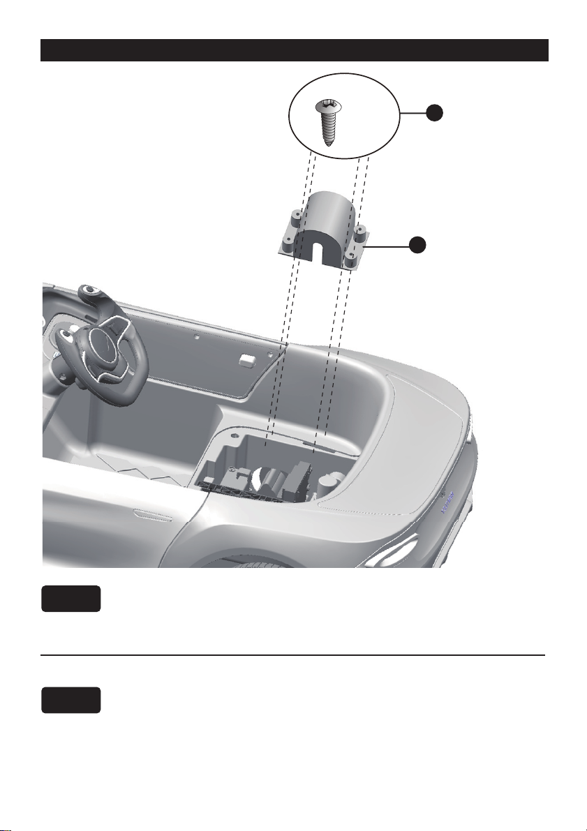
Attach the Steering Wheel │ 8
End of Steering column
HINT: Batteries not included. Refer to the battery information on page 4.
Remove the M5x40 machine screw and Ø5 nut from the steering wheel.
5. Place the steering wheel over the steering column, protruding from the middle of
the steering wheel base.
6. Align the holes on each side of steering wheel with the holes at the end of the
steering column.
7. Fasten a nut on the opposite end of the screw to
secure the steering wheel to the steering
column.
1. With a screwdriver remove the
screw on the battery cover
located in the center of the
steering wheel.
2. Remove the battery cover from
the top of the battery
compartment.
3. Insert two AA batteries in their
correct polarities.
4. Place the battery cover over the
battery compartment and fasten
with the screw you removed in
step one.
Add the Batteries (Not included) of Steering Wheel
Attache the Steering Wheel

2
1
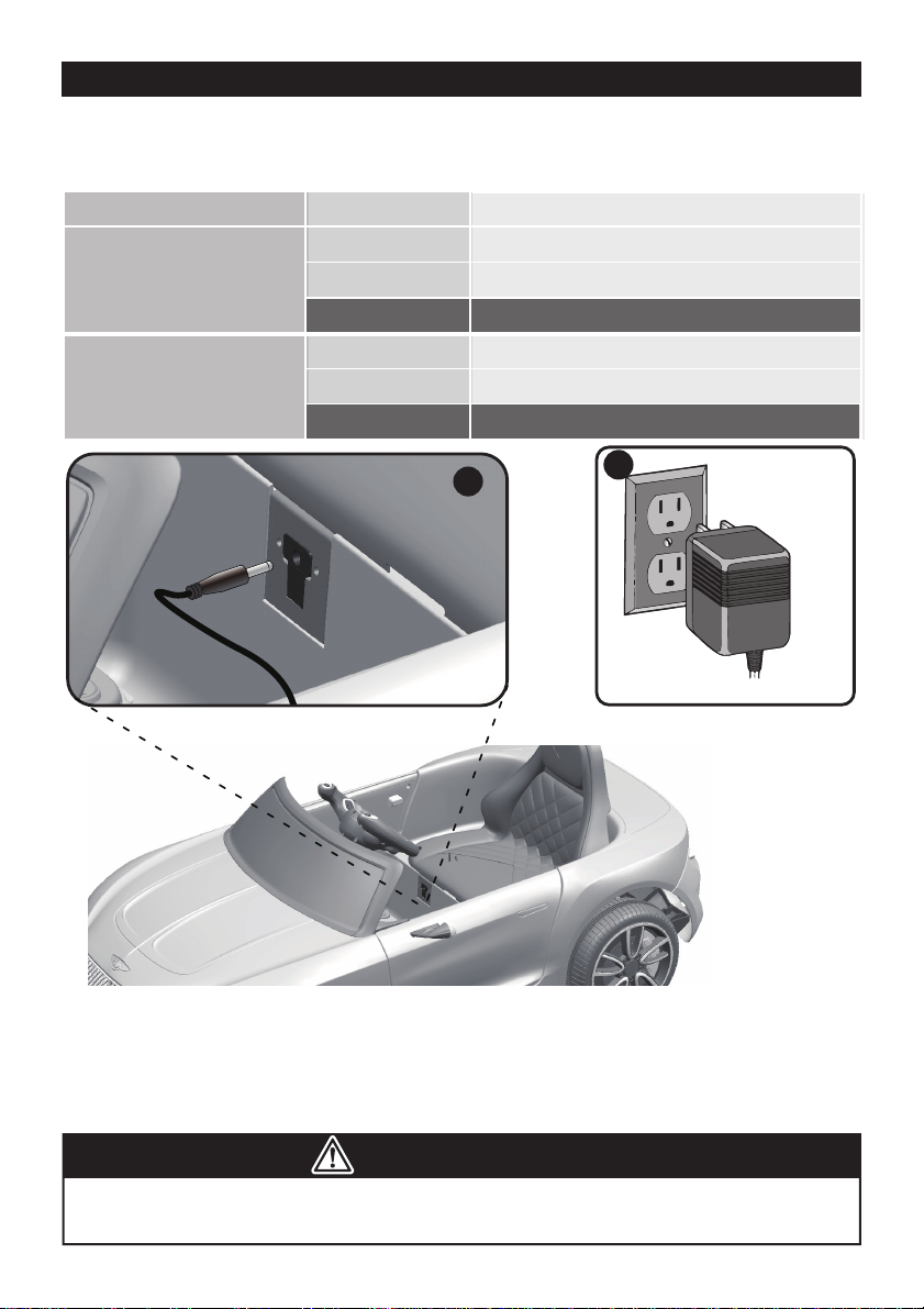
Connect the Power Supply │ 9
Rear Top View
Fuse
box
Battery
Vehicle
connector
Motor connector
1WD
2WD
1. Plug the red fuse connector into the terminal on battery.
2. Plug the vehicle connector into the motor connector on body as shown
above.
1. Plug the red fuse connector into the terminal on battery.
2. Plug the vehicle connector into the motor connector on body as shown
above. Repeat for the other side.
1
2
x4
Attach the Motor Hood │ 10
1. Fit the motor hood on the motor.
2. Tighten four ø4x12 flat head screws to secure it.
1. Fit the motor hood on the motor.
2. Tighten four ø4x12 flat head screws to secure it.
Repeat the above steps for the other motor hood.
Rear View
1WD
2WD
x2
2
1
3
4
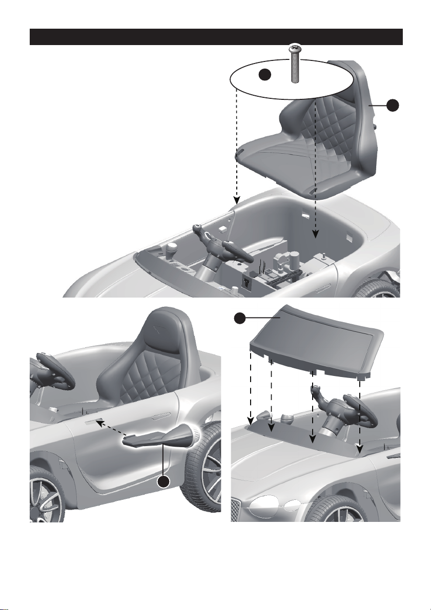
Attach the Seat, Mirrors & Windshield │ 11
1. Fit the tabs on the back of seat into
the slots on the rear vehicle.
2. Tighten two M5x16 machine screws
to secure it with a screwdriver.
3. Fit the mirror into the hole on side of
vehicle. Repeat for the other side.
4. Insert the tabs on the windshield
into the slots on the vehicle, push
until you hear it “click” into place.
Side View Front View

PREVENT INJURIES AND DEATHS:
• NEVER LEAVE CHILD UNATTENDED. DIRECT ADULT SUPERVISION IS
REQUIRED. Always keep child in view when child is in vehicle.
• This toy should be used with caution since skill is required to avoid falls or
collisions causing injury to the user or third parties.
• Protective equipment should be worn.
• Never use in roadways, near cars, on or near steep inclines or steps,
swimming pools or other bodies of water.
• Always wear shoes.
• Always sit on the seat.
• Not to be used in traffic.
• This toy is unsuitable for children under 36 months due to its maximum
speed; Maximum user weight is 30 kgs.
• This toy has no brake.
Rules for Safe Riding
• This vehicle has adjustable play seat belts. Please instruct children how to tie the
safety belt before using, guarantee the security.
• Keep Children within Safe Riding Areas:
- Never use in roadway, near motor vehicles, on lawn space, on or near steep
inclines or steps, swimming pools or other bodies of water;
• Use the toy only on flat surfaces. Such as inside your house, garden or
playground.
• Never use in the dark. A child could encounter unexpected obstacles and have
an accident. Operate the vehicle only in the daytime or a well-lit area.
• It is prohibited to change the circuit or add other electric parts
• Inspect wires and connections of the vehicle periodically.
• Do not let any child touch the wheels or be near them when the car is moving .
WARNING!
Use the vehicle on generally level ground ONLY!
DO NOT Use the vehicle on Lawn space!
Safety │ 12

3
42
6
8
7
1
5
Make sure your child knows how to steer, how to start and stop the vehicle and knows
the rules for safe driving. The vehicle can be driven at a maximum of 2.5~5 km/h.
ADVANCED USE - High speed Drive
1. Power Switch: Turns the vehicle on and off.
2. Forward/reverse switch: Changes the direction that vehicle moves from forward to
reverse.
● To move the car forward, rock the switch to “forward” position.
● To move the car backward, rock the switch to “reverse” position.
3. Sounds buttons (IF EQUIPPED): Press for sounds playing.
4. Volume knob (IF EQUIPPED): Turn the knob clockwise to increase the volume; Turn
the knob counterclockwise to decrease the volume.
5. Foot pedal: Applies power (speed) to the vehicle.
● To move the car, press the pedal down.
● To brake or slow down, release pressure from the pedal.
6. Auxiliary input (IF EQUIPPED): Allow the audio from your portable music player or
phone to be played through the vehicle speakers.
7. NO FUNCTION.
8. High/Low speed switch (IF EQUIPPED): The switch operates the vehicle to move
forward in low or high speed.
Use Your Ride-on │ 13
Always stop vehicle
when changing the
speed or direction to
avoid damage the
gears and motor.
Your vehicle may be equipped with the MP3 player, see the next page please!
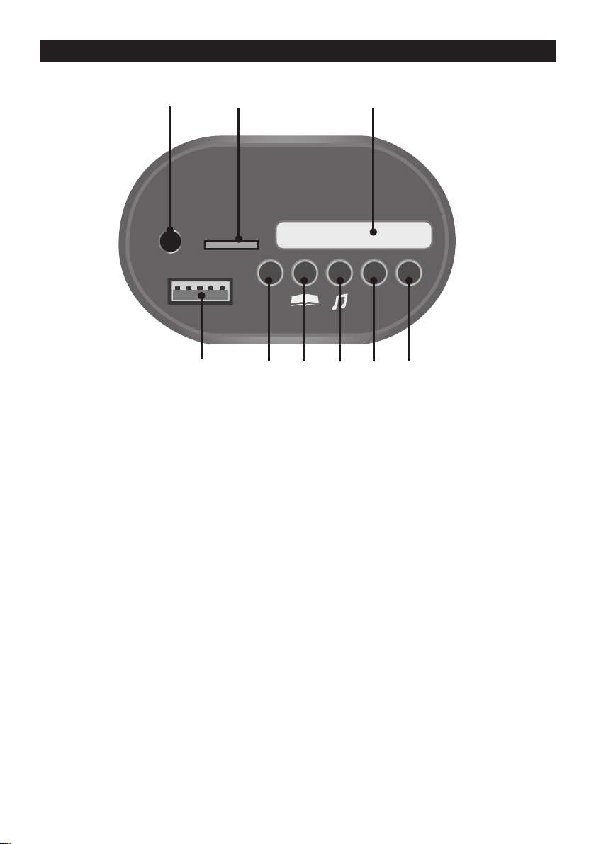
ABC
TF
MP3
USB v+ v-
B
G
H
IC
A
DEF
Use the Multi-function Dash (IF EQUIPPED) │ 14
A. Digital voltmeter: Check the power remaining of your battery, refer to page 19.
B. English learning mode
C. Storytelling mode
D. Nursery rhyme singing mode
E. Increase volume
F. Decrease volume
G. TF (Micro SD) card slot: Allow the audio from your TF card to be played
through the vehicle speakers. MP3 format ONLY.
H. 3.5mm AUX input (AUX input): Allow the audio from your portable music
player or phone to be played through the vehicle speakers. MP3 format ONLY.
I. USB interface: Allow the audio from your portable device to be played through
the vehicle speakers. MP3 format ONLY.
ASSEMBLY
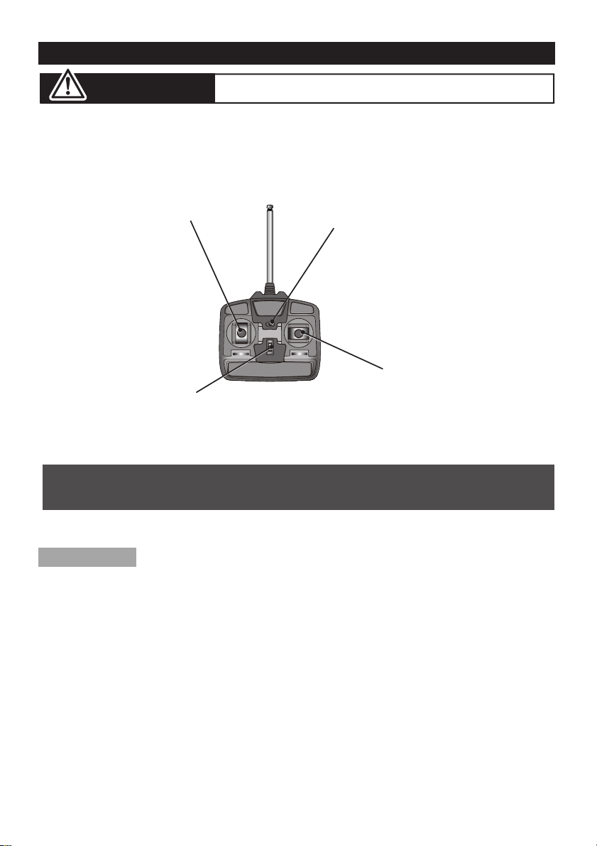
1. Insert the antenna into the controller by tweak the antenna clockwisely;
2. Lift the battery compartment door on the back of the controller and
insert two AA(LR6) batteries.
NOTE: Batteries not included.
Refer to the battery information on page 4.
ON-OFF SWITCH
INDICATOR LIGHT
RIGHT JOYSTICK
LEFT JOYSTICK
Use the Normal Remote Controller (IF EQUIPPED) │ 15
ADULT OPERATING REQUIRED!
WARNING:
The remote control has precedence over foot pedal operation.
(The foot pedal won’t work while you operate the Remote Controller)
Your vehicle may be equipped with a 2.4G REMOTE
CONTROLLER, see the next page please.
This remote controller may with function of firt priority
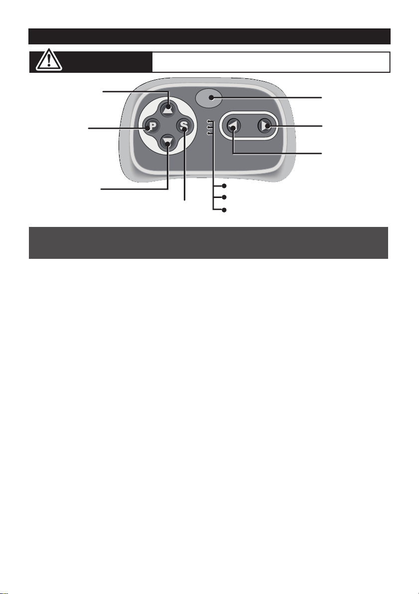
Use the 2.4G Remote Controller (IF EQUIPPED) │ 16
ADULT OPERATING REQUIRED!
WARNING:
1. Connection button (build connection)
Long press the Connection button for 2~4 seconds first, then turn on the
power button located on the vehicle dashboard console, when the low speed
indicator goes from flashes into long bright, means the connection successful.
If the low speed indicator only flashes, means the connection failed. Replace
the batteries and repeat the steps above.
2. Brake button
Press the button to stop the vehicle, press it again to release the brake.
3. Speed select button
The switch operates the vehicle to move in low, normal or high speed.
HINT: The vehicle is designed to operate in low speed only in reverse.
• Leave the remote controller idling for about 10 seconds, it will shut down
automatically.
• Repeat step 1 when you replace the batteries of the remote controller.
INSERT THE BATTERIES
Lift the battery compartment door on the back of the controller and insert
two AAA(LR03) batteries.
NOTE: Batteries not included.
Refer to the battery information on page 4.
NOTE:
The remote control has precedence over foot pedal operation.
(The foot pedal won’t work while you operate the Remote Controller)
Connection
button
Forward button
Left turning
button
Right turning
button
Brake button
Speed select button
High speed indicator
Normal speed indicator
Low speed indicator
Reverse button

Use the Door Lock │ 17
Door inside
Door Lock
NOTE:
Please close the door and ensure the lock snap into place when
riding for safety consideration.

ONLY AN ADULT CAN CHARGE AND RECHARGE THE BATTERY!
• PREVENT FIRE AND ELECTRIC SHOCK:
- Use the only rechargeable battery and charger supplied with your vehicle. NEVER substitute the battery
or the charger with another brand. Using another battery or charger may cause a fire or explosion.
- Do not use the battery or charger for any other product. Overheating, fire or explosion could occur.
- NEVER modify the electric circuit system. Tampering with the electric system may cause a shock, fire or
explosion or may permanently damage the system.
- Do not allow direct contact between battery terminals. Fire or explosion can occur.
- Do not allow any type of liquid on the battery or its components.
- Explosive gasses are created during charging. Do not charge near heat or flammable materials. Charge
the battery in a well-ventilated area ONLY.
- NEVER pick up the battery by the wires or charger. Damage can occur to the battery and may cause a
fire. Pick up the battery by the case ONLY.
- Charge the battery in a dry area ONLY.
• Battery posts, terminals and related accessories contain lead and lead compounds, chemicals
known to the State of California to cause cancer and reproductive harm. Wash hands after
handling.
• Do not open the battery. Battery contains lead acid and other materials that are toxic and
corrosive.
• Do not open the charger. Exposed wiring and circuitry inside case may cause electric shock.
• Only adults may handle or charge the battery. NEVER allow child to handle or charge the
battery. Battery is heavy and contains lead acid (electrolyte).
• Do not drop the battery. Permanent damage to the battery could occur or cause serious injury.
• Before charging the battery, check for wear or damage to the battery, charger, its supply cord
and the connectors. DO NOT charge the battery if any damage to parts has occurred.
• Do not allow the battery to drain completely. Recharge the battery after each use or once a
month if not used regularly.
• Do not charge battery upside down.
• Always secure the battery with the bracket. Battery can fall out and injure a child if vehicle tips
over.
WARNING!
• The POWER SWITCH must be turned in OFF position when charging.
• Before the first use, you should charge the battery for 4-6 hours. Do not recharge
the battery for more than 10 hours to avoid overheating the charger.
• When the vehicle begins to run slowly, recharge the battery.
• After each use or once a month minimum recharge time as 8 to 12 hours, less
than 20 hours at most.
Charging │ 18
6V4Ahx2, 6V7Ahx2, ≥ 13.2
13.1~12.6
≤ 12.5
2
1
6V4Ahx1, 6V7Ahx1 ≥ 6.6
6.5~6.3
≤ 6.2
• If your ride-on with a Digital voltmeter(IF EQUIPPED), the magnitude of voltage
will tell you how much power is remaining in the battery when you must
recharge the battery. Make sure the vehicle is stop!
BATTERY
MAGNITUDE OF VOLTAGE
BATTERY STATE
1. Plug the charger port into the input socket. (the socket is below the seat)
2. Plug the charger plug into a wall outlet. The battery will begin charging.
WARNING!
This product with Charging Protection: when charging, all functions will be cut
off! Only an adult can charge and recharge the battery!
The battery is full.
The vehicle can work normally.
The battery needs to be charge.
The battery is full.
The vehicle can work normally.
The battery needs to be charge.
Charging │ 19
Table of contents


