Motorised Battery Switch
Model: 720-MDO (Version 8)
OPERATION AND INSTALLATION INSTRUCTIONS
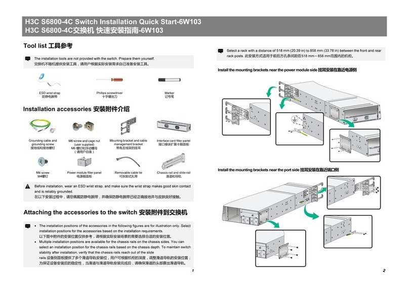
The 720-MDO Version 8 offers a number of advanced installation options, whereby the motor/circuit board
can be fed from an independent 12V or 24V supply, so the switch contacts are fully isolated and can:
• Stillbeoperatedincasetheswitchedbatteryisat
• Control higher voltage circuits e.g. 32 or 48 volt circuits
• Control negative cables in circuits (e.g. full isolation in metal hulled craft)
• Ensure engine electronics are fully isolated from all loads
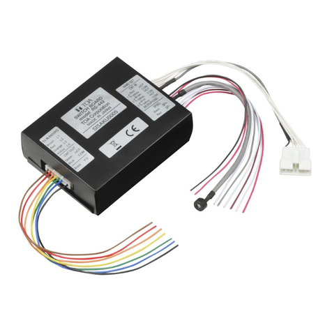
• NoteVersion8720-MDO’scanbeidentiedbythe7coreconnectioncablewith3coresterminatedinthe
Wago plug, and 4 cores crimp-terminated
Typical installation is with a
key-operated switch at the helm
station and with the motorised
battery switch installed as close
as practical to the battery bank.
Although any switch may be used
BEP offer the specially developed
80-724-0006-00 key switch
(pictured at right).
Another option is to use BEP’s Wireless Remote
Control. This is similar to a car remote, and
provides access from up to 80m. Working
through a 4 channel relay, the wireless
remote (part number 80-911-0045-00)
canbeconguredtocontrolitemssuch
as motorised battery switches, entry
lights, hatch lifters etc in order to
offer safe, easy entry to your vessel
(pictured at right).
SPECIFICATIONS:
• Continuous rating: 500 Amps DC - minimum 2x95mm²
(2x3/0)cables
• Intermittent rating: 700 Amps DC - minimum 2x95mm²
(2x3/0)cables
• Cranking rating: 2500 Amps DC - minimum 2x95mm²
(2x3/0)cables
• Maximum Voltage: 32VoltsDC(formotor/PCBsupply)
50 Volts DC (switch contacts – note
motor/PCBsupplyrequires12/24volts)
• Auto operating range: 8 to 32 Volts DC
• Operation: ManualOn/Off,AutoOn/Off
• Mounting: Recessed or surface
• Ignition protected Meets UL 1107 standards
• IP Rating IP65
• Stud Size: 2x12mm(1/2”)–SeeInstallation
sectionfortorques
• Materials: Tinnedcopperconductors/studs,
stainless steel nuts, high temperature
brereinforcedplastics
• Power draw: Switch in off positions: <=5mA@12V or 24V
Switch in “Auto On” 9mA @12V,
13.5mA @24V
Wires For Standard Connection:
Red •LEDWire
Green •ControlWireFrom
Remote Switch
Black •SupplyNegative
Input Stud •HighCurrentConnection
From Battery
Ouput Stud •HighCurrent
Connection To Loads
Terminated into
Wago plug
}
Wires For Advanced/Optional Connections:
Brown •PowerSupplyFromInputStud
Orange •Motor/PCBSupplyPositive#1
Brown takes power from the Input stud, and
Orangetakesthistothecircuitboard/motorto
control the battery switch.
Blue •PowerSupplyFromOutputStud
White •Motor/PCBSupplyPositive#2
Blue takes power from the Output stud. White is
a secondary connection to provide power to
circuitboard/motor.Bothisolatedasstandard.
Supplied
connected
Supplied
isolated
}
}
