Wiring
A
. Single Line Wiring
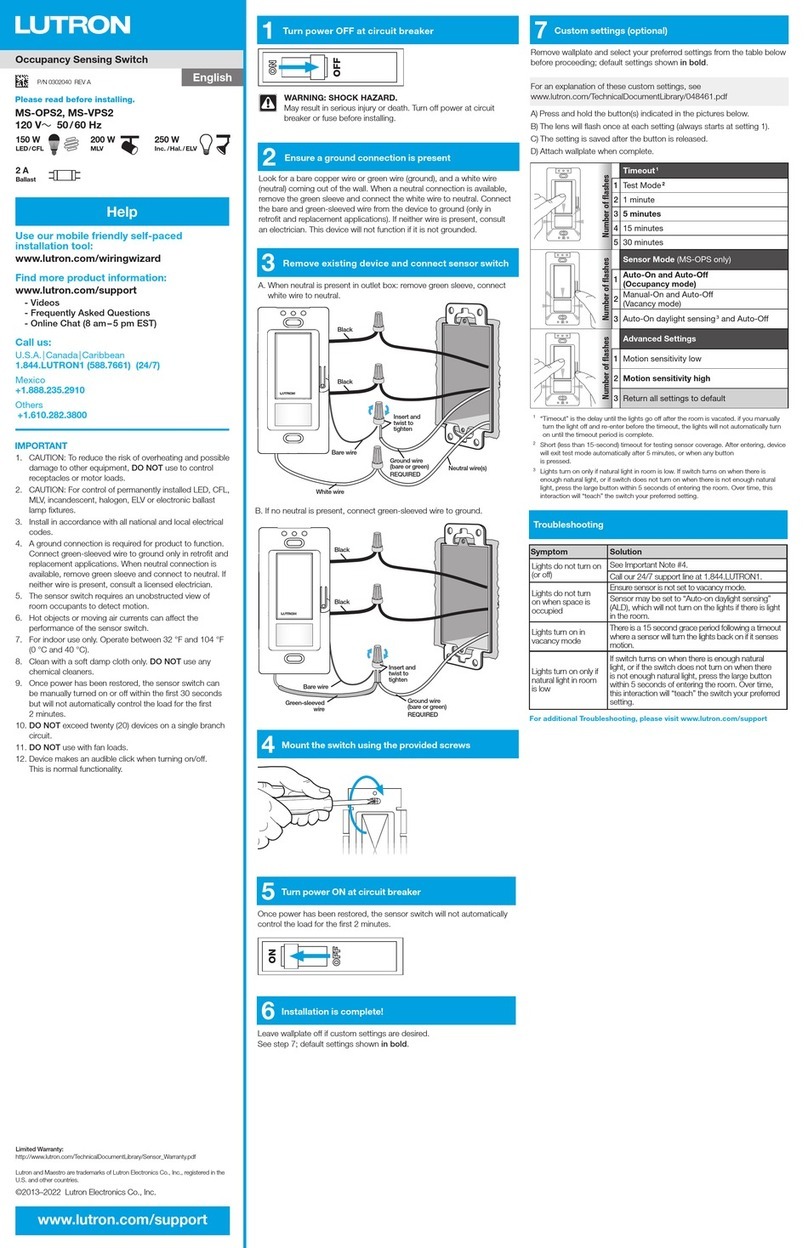
2Connect sensing switch
WARNING! Shock Hazard. May result in serious injury or death.
Turn power OFF at circuit breakers before installing the unit.
1Turn power OFF
I
I
I
O
O
O
®
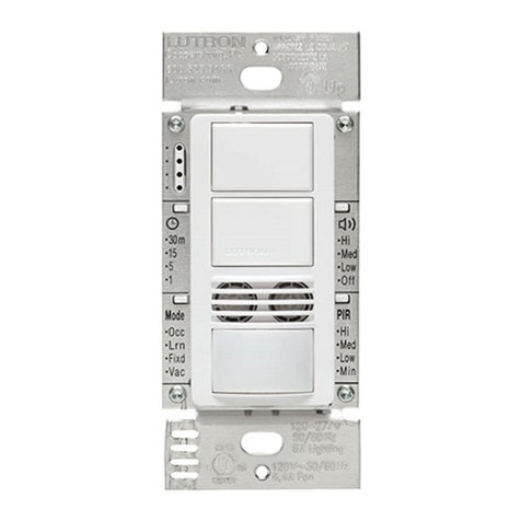
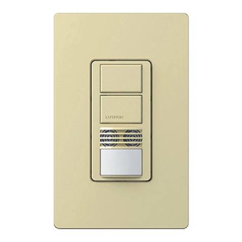
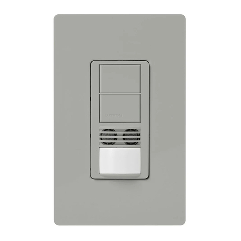
Dual Circuit
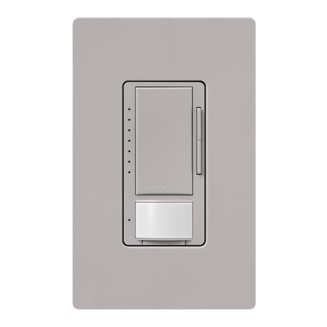
Dual Technology Sensing
Switch Installation Guide
Lighting
120-277 V~50 / 60 Hz 6 A
Fan
120 V~50 / 60 Hz 4.4 A 1/6 HP
Combined lighting and fan load
120 V~50 / 60 Hz 4.4 A
MS-B202
Occupancy
Lutron Electronics Co., Inc.
7200 Suter Road
Coopersburg, PA 18036-1299
www.lutron.com
P/N 032445 Rev. A
11/2013
®
Limited Warranty (Valid only in U.S.A., Canada, Puerto
Rico, and the Caribbean). Lutron will, at its option,
repair or replace any unit that is defective in materials
or manufacture within five years after purchase. For
warranty service, return unit to place of purchase or mail
to Lutron at 7200 Suter Rd., Coopersburg, PA 18036-
1299, postage pre-paid. This warranty is in lieu of all
other express warranties, and the implied warranty of
merchantability is limited to FIVE years from purchase.
This warranty does not cover the cost of installation,
removal or reinstallation, or damage resulting from
misuse, abuse, or damage from improper wiring or
installation. This warranty does not cover incidental
or consequential damages. Lutron’s liability on any
claim for damages arising out of or in connection
with the manufacture, sale, installation, delivery,
or use of the unit shall never exceed the purchase
price of the unit. This warranty gives you specific legal
rights, and you may have other rights which vary from
state to state. Some states do not allow the exclusion
or limitation of incidental or consequential damages, or
limitation on how long an implied warranty may last, so
the above limitations may not apply to you.
Lutron and Maestro are registered trademarks of
Lutron Electronics Co., Inc.
© 2013 Lutron Electronics Co., Inc.
Major motion coverage:
30 ft × 30 ft (9 m × 9 m) [900 ft2(81 m2)]
Minor motion coverage:
20 ft × 20 ft (6 m × 6 m) [400ft2(36m2)]
3Turn Power ON
I
I
I
O
O
O
P/N 032445 Rev. A
11/2013
Troubleshooting
Symptoms Possible Solutions
Sensing switch
is unpowered, or
is powered, but
does not turn
lights ON.
• If installed in a 3-way with
another mechanical switch, be
sure to rewire the mechanical
switch using Wiring step 2B.
Power can’t be
switched ON or
OFF with newly
installed sensing
switch.
• Check wiring; neutral wire must
be connected for product to
function.
Lights do not turn
ON when space is
occupied.
• Off-While-Occupied mode is
Enabled and the timeout has
not expired.
• Sensor mode is set to vacancy.
• Sensor is set to one of the
Ambient Light Detection (ALD)
settings and the room is too
bright for the current light level
setting.
• Sensor does not have full view
of the room. Move objects
blocking sensor’s line-of-sight.
•Before installing wallplate, program all desired settings. See back for programming instructions.
• For additional wiring instructions, including wiring for two separate breaker feeds, please visit
www.Lutron.com/DTMaestroInstall
For additional features, wiring help,
troubleshooting, and product information
please visit:
www.lutron.com / DTMaestroInstall
4Wait for 2 minutes
• The sensing switch will manually control the load after the first 10 seconds.
• Once power has been restored, the sensing switch will automatically control the load after the first
2 minutes.
Important Notes
Please read before installing.
1. Neutral wire required.
2. Device will not function if Black wires (Circuit 1/
Line 1) are not wired.
3. This product is rated to control 6 A per circuit.
Circuits may NOT be wired in parallel to control
loads greater than 6 A.
4. When power is applied, the sensing switch
can be manually turned on or off after the first
10 seconds and will automatically control the
load after 2minutes.
5. CAUTION: Risk of Electric Shock— More than
one disconnect switch may be required to de-
energize the equipment before installing the unit,
rewiring, or replacing bulbs.
6. The sensing switch requires an unobstructed
view of the room and line-of-sight to detect
motion.
7. Hot objects or moving air currents can affect
the performance of the sensing switch and
may cause the sensor to turn on unexpectedly
or maintain its current state longer than
desired.
8. CAUTION: To reduce the risk of overheating
and possible damage to other equipment,
DO NOT use to control receptacles.
9. Install in accordance with all national and local
electrical codes.
10. For indoor use only. Operate between 32°F
and 104°F (0 °C and 40 °C).
11. Clean with a soft damp cloth only. DO NOT
use any chemical cleaners.
B
. 3-Way with Mechanical Switch
• Rewire your mechanical switch in a 3-way. 3-way wiring for sensing switch is different than
traditional 3-way wiring.
m30
15
5
1
Occ
Lrn
Fixd
Vac
Mode
Hi
Med
Low
Off
Hi
Med
Low
Min
PIR
Neutral
Black
1Black
1
Load 1
Load 2
Green
Black-Orange
White
Line/Hot Blue
Black-Orange
m30
15
5
1
Occ
LRN
Fixd
Vac
Mode
Hi
Med
Low
Off
Hi
Med
Low
Min
PIR
m30
15
5
1
Occ
Lrn
Fixd
Vac
Mode
Hi
Med
Low
Off
Hi
Med
Low
Min
PIR
Black
1
Blue
Ground
Two Circuit
Switch
Green
Ground
120–277 V~
50 / 60 Hz
Line/Hot
Load 2
Standard
Mechanical Switch
2,3
Black
1
Yellow
Jumper
wire
(included)
Different
color
screw
Neutral
Load 1
White
Black-Orange
Two Line Wiring:
Wiring must comply with NEC code for wiring Multiple Branch Circuits: Where two or more branch
circuits supply devices or equipment on the same yoke, a means to simultaneously disconnect
the ungrounded conductors supplying those devices shall be provided at the point at which the
branch circuits originate.
Two circuits, each rated at:
Black-Orange
Ground
1Device will not function if Black wires are not wired.
2Mechanical switch may be wired to either circuit, and will control both. Do NOT wire mechanical switch to both circuits.
3You may use no more than one mechanical switch with a Dual circuit Dual Tech sensor switch.
