BEP Marinco ProInstaller 771-S-EZ 400A User manual
EZ Mount Selector Battery Switch
771-S-EZ 400A EZ Mount Selector (Retail Packed)
771-S-EZ-B (Bulk Packed)
Features & Benefits:
•Easiest surface mounting, saves installation time and cost
•Front access studs match Pro Installer Busbar range intercon-
nection height for direct linking and most compact mounting
footprint
•Actuator assembly can be tted at any 90 degree angle for
optimal cabling exibility
•Removable knob for isolation/safety
•Includes back cover and three side panels for security and
cable protection
•Designed to withstand harsh marine environments
•High temperature reinforced plastics
Specifications:
• Continuousrating:400A*
• Intermittentrating(5minutes):600A*
• Crankingrating(10seconds):1500A*
• Connectionstudsize:M10(3/8”)
• 12-48VDC
• IP66–protectionfrompowerfulwaterjets
• Ignitionprotected
• IndependentlytestedtomeetUL1107standards
• CE
* Electricalratingsachievedusingcablesize120mm²
Installation Instructions: IMPORTANT!
Read before installing
•It is recommended that electrical terminations and connections
are carried out by a marine electrical technician.
•These battery switches are for isolation purposes and are not
designed for switching under load.
•Ensure there are no circuits with high inductive loads directly
connected to the switch in order to prevent any sudden in-rush
of current which may cause damage to the switch.
•Although specially selected chemical resistant materials have
been used, we recommend that for maximum product life only
plastic safe corrosion inhibiting sprays are used.
• Ensureallcablesaresizedcorrectlyfortheloadstheycarry.
Please refer to www.bepmarine.com to calculate correct cable
sizes.
•Ensure all electrical connections are correctly tightened to
prevent any damage to the battery switch.
• WARNING:Donotswitchbatteryswitchtooffpositionwhile
the engine is running.
T
O
R
Q
U
E
Plastic safe
Petroleum
based
solvents
1 2
Aseasytomountas1,2,3,theserevolutionarybatteryswitches
allow you to wire from the front.
1. Fit base
2. Addwiring
3. Cliponactuator
With their shared interconnection height, EZ-Mount Selector
batteryswitches“cluster”directlywiththeProInstallerBusbar
Range, resulting in the fastest, most compact installations. All
ratings, footprints and construction of the EZ-Mount Selector
switches match the high quality of our standard switches.
1 2
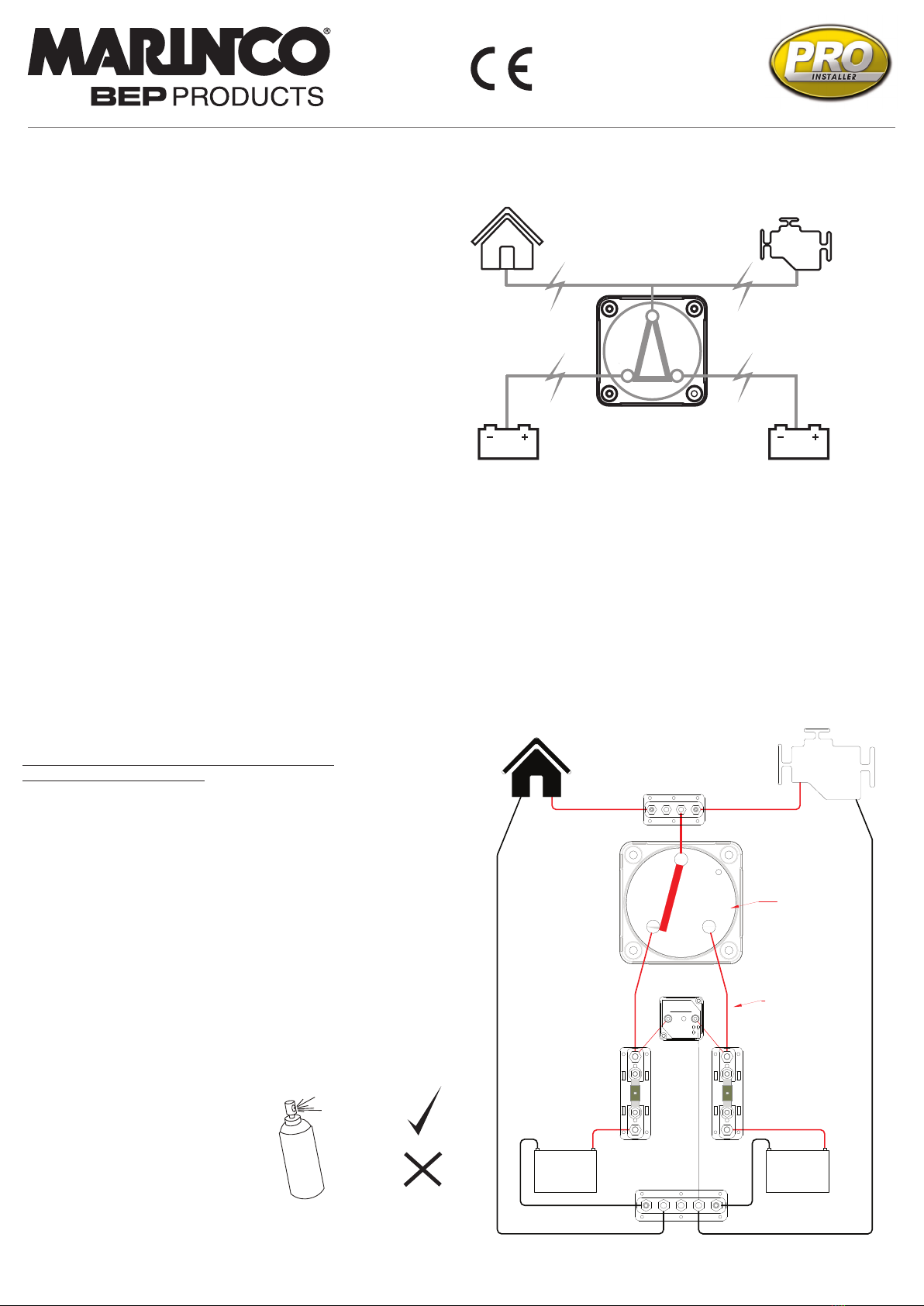
Loads
Engine
Loads
Battery
2
+
-+
-
Battery
1
DVSR
Negative
Bus
Battery
1
Fuse
Battery
2 Fuse
Example System: NOTE -This
diagram is a guide only showing
Selector connections and is not
intended as a full electrical systems
wiring diagram.
DVSR (710-140A)
provides automatic
battery charging
of second bank
Note: Battery 1 and 2
designation when viewing
EZ mount base with
Actuator removed

EZ Mount Installation (Surface Mount Only)
1. Disconnect battery positive leads at the batteries for safety
2. Choose mounting location on a at surface close to the
batteries
3. Select pan head (or similar) screws for mounting - use either
M5 or 10g imperial (not included)
4. With Actuator removed, use the switch base as a mounting
template to mark the hole positions. (See separate
instructions for Actuator removal/tting)
5. Drill holes and screw switch base into position
6. Connect cables to studs ensuring that batteries and loads are
correctly tted
7. Ensure cables are secured to ISO/ABYC standards, and that
cables are supported so they are not placing unnecessary
strain on the battery switch studs
8. Check that spring washers are tted beneath nuts
9. Tighten the stud nuts to 13.5 Nm (10 lbf)
10. Slot the side panel(s) into the Actuator as required
11. Replace Actuator, ensuring that both switch base and
Actuator are both in their “OFF” positions
12. Lock the Actuator fastening screws
13. With switch in “OFF” position connect battery positive leads
at battery
14. Check switch operation
Check switch operation:
a. Loads have no voltage in “OFF” position
b. Loads have voltage from battery 1 in “1 ON” position
c. Loads have voltage from battery 2 in “2 ON” position
d. All connections are paralleled in “1&2” position
Fit Actuator at
0, 90, 180, or
270 degrees
to suit cabling
ON
ON
1&2
12
OFF
ON
ON
1&2
12
OFF
ON
ON
1&2
12
OFF
ON
ON
1&2
12
OFF
O Position For
Switch Base, When
Arrow On Shaft
Points At "OFF"
Always remove &
replace Actuator with
knob in the "OFF"
position
OFF
ON
ON
1&2
12
Replacement of Actuator (always remove, and replace the
Actuator with knob in the “OFF” position)
1. Check that switch contact shaft (on base) hasn’t been rotated, and
that arrow on base shaft is pointing towards “OFF” engraving
2. Ensure that that light grey fastening screws are in the “unlocked”
position
3. Ensure that Actuator knob is rotated to the “OFF” position
4. Note that Actuator can be tted at any position 0/90/180/270 to suit
electrical cabling
5. Replace Actuator
97.8 [3.85]
15.6 [0.61] 76.9 [3.03]
92.5 [3.64]
62.4 [2.46] 30.1 [1.19]
27.5 [1.08]
97.8 [3.85]
97.8 [3.85]
76.2 [3.00]
76.2 [3.00]
5.5 [0.22]
Dimensions:
Removal of Actuator (always remove, and replace the
Actuator with knob in the “OFF” position):
1. Ensure knob is on “OFF” position
2. Undo light grey fastening screws by rotating 45 degrees
anticlockwise
3. Remove Actuator
UNLOCKED
LOCKED
ON
ON
1&2
12
OFF
Surface
EZ-Mount
Rear
Panel
Mount
Front
Panel
Mount
Surface
EZ-Mount
Rear
Panel
Mount
Front
Panel
Mount
Surface
EZ-Mount
Rear
Panel
Mount
Front
Panel
Mount
Learn more about marine electrical distribution we have.
This manual suits for next models
1
Other BEP Switch manuals

BEP
BEP MARINCO PRO INSTALLER 771-SFD User manual

BEP
BEP Smart Battery Hub Guide

BEP
BEP Marinco 770-EZ User manual

BEP
BEP Marinco ProInstaller 770-EZ 400A User manual

BEP
BEP MARINCO 771-S-EZ User manual

BEP
BEP 720-MDO User manual

BEP
BEP Pro Installer MARINCO 770-EZ User manual

BEP
BEP 720-MDO-EP Specification sheet


