Berg Engineering & Sales Company SonoDur-R NS-2227690 User manual

NewSonic SonoDur-R Issue 105 06/2020 Page 1
SonoDur-R Instruction Manual
Automated UCI-Hardness Testing System
with
Motorized and Hand-Held Probes
This edition 105, 04/2020 applies to software version V1.00 and higher using
Android Operating System, SonoDur-R.
Original operating instructions EN_SonoDur-R_Android_V105
This document is subject to technical changes without prior notice.

Table of Contents
NewSonic SonoDur-R Issue 105 06/2020 Page 2
Note concerning this manual
Please read this operating manual carefully before starting any work! Lack of understanding or lack
of knowledge can lead to false test results and have unforeseeable consequences! In particular,
observe all safety instructions in this manual and the applicable regulations at your site of operation.
Illustrations and photos in this manual are intended to facilitate basic understanding, and may differ
from the actual design.
Initial commissioning
Upon initial commissioning, take note of chapter 4, page 10 et seq. as well as the safety instructions
in Chapter 2.2, page 7.
Copyright notice
Copyright 2020 NewSonic GmbH. All rights reserved.
Use of this manual is permitted in the context of using the device. Any further use requires the
consent of the manufacturer.
In particular, no part of this manual may be reproduced, altered, duplicated or stored in any form
whatsoever without the express permission of NewSonic GmbH. Excluded therefrom is a security
copy provided for the personal use of the buyer.
Limitation of Liability
All information and instructions contained in this operating manual were compiled in accordance
with statutory standards and regulations, state of the art technology and our long-standing
knowledge and experience However, NewSonic GmbH will not guarantee the accuracy and
completeness of this operating manual.
NewSonic GmbH shall not assume liability for direct, indirect or accidental damages associated with
the operating manual or the products described in this manual.
Liability for damage or warranty claims shall become void in the event of:
•Failing to comply with this manual
•Failing to comply with applicable safety and accident regulations
•Improper use
•Deployment of untrained personnel
•Technological changes
•Utilizing non-original spare parts and accessories
The actual scope of delivery may deviate from the illustrations and descriptions described in the
document at hand because of technical changes or special designs on customer request. NewSonic
GmbH reserves the right to apply changes to products or documentations at any time and without
giving notice. Moreover, the responsibilities agreed in the delivery contract, the General Terms and
Conditions as well as the delivery conditions of the manufacturer and the statutory regulations as
valid at the time of conclusion of the contract shall apply.
In case of questions, please contact the nearest NewSonic representative or visit us online at:
https://www.newsonic.de/

Table of Contents
NewSonic SonoDur-R Issue 105 06/2020 Page 3
1Table of Contents
1 Table of Contents ............................................................................................................................ 3
2 Introduction..................................................................................................................................... 6
2.1 Measuring methods and suitable test materials..................................................................... 6
2.2 Safety Instructions................................................................................................................... 7
2.3 Designated Use........................................................................................................................ 8
2.4 Highlighting warnings and other instructions ......................................................................... 8
2.5 Prerequisite for the hardness test........................................................................................... 8
3 Device Connections, On/Off-Switch................................................................................................ 9
4 Preparation for operation ............................................................................................................. 10
4.1 Supply Input Voltage ............................................................................................................. 10
4.2 Connecting and disconnecting the test probe ...................................................................... 10
4.2.1 Connecting the test probe or test device...................................................................... 11
4.2.2 Disconnecting the test probe or test device ................................................................. 11
5 Switching On and Off..................................................................................................................... 12
5.1 Power ON .............................................................................................................................. 12
5.2 Switching OFF ........................................................................................................................ 13
6 Operating....................................................................................................................................... 14
6.1 Start the Test Program .......................................................................................................... 14
6.1.1 Measuring Menu (Main Menu) ..................................................................................... 14
6.1.2 Simulation Mode ........................................................................................................... 14
6.2 Der Start Screen (Home Screen)............................................................................................ 16
6.3 Change Language .................................................................................................................. 17
6.3.1 Delete Language............................................................................................................ 19
7 Operation and Menu Structure..................................................................................................... 20
7.1 Description of the Operating Elements on the Bottom Menu Bar ....................................... 20
7.2 Buttons –Control Elements (Soft Keys) ................................................................................ 20
7.3 Entry input via the system keyboard..................................................................................... 23
7.4 Main Menu Measuring.......................................................................................................... 23
7.4.1 Signal Monitor ............................................................................................................... 25
7.5 Performing a measurement with motor measuring probes ................................................. 26
7.5.1 Automatic measuring with motor probe ...................................................................... 26
7.5.2 Manual measuring types with motor probe ................................................................. 28
7.6 Performing a measurement with hand-held measuring probes........................................... 30

Table of Contents
NewSonic SonoDur-R Issue 105 06/2020 Page 4
7.7 Information Menu ................................................................................................................. 32
7.8 Instrument Menu .................................................................................................................. 35
7.9 Adjustment............................................................................................................................ 35
7.9.1 Adjusting the measuring value...................................................................................... 35
7.9.2 Adjusting number directly............................................................................................. 37
7.9.3 Deleting Adjustments.................................................................................................... 38
7.9.4 Saving and Loading Adjustments................................................................................... 39
7.10 Conversions ........................................................................................................................... 41
7.10.1 Hardness Scale............................................................................................................... 41
7.10.2 Standard (Norm)............................................................................................................ 41
7.10.3 Materials........................................................................................................................ 42
7.10.4 Presentation of the measurement values outside the conversion limits ..................... 42
7.11 Settings.................................................................................................................................. 43
7.11.1 Thresholds (Specification Limits)................................................................................... 43
7.11.2 Penetration time (Dwell Time) ...................................................................................... 44
7.11.3 Motor / Manual............................................................................................................. 45
7.11.4 Automatic Closing.......................................................................................................... 45
7.11.5 Maximum Number of Measurements in one File ......................................................... 48
7.11.6 Tester............................................................................................................................. 48
7.11.7 Number Format ............................................................................................................. 49
7.11.8 Presentation of Measuring Value.................................................................................. 50
7.11.9 Comment Function........................................................................................................ 50
7.12 SonoDur Data Processing ...................................................................................................... 51
7.12.1 Storing Data................................................................................................................... 51
7.12.2 Opening File (Load File) ................................................................................................. 51
7.13 Data transmission and interfaces.......................................................................................... 54
7.13.1 USB Interface................................................................................................................. 54
7.13.2 RS232 Schnittstelle........................................................................................................ 56
7.13.3 Remote Control Commands .......................................................................................... 57
7.13.4 Digital Interface ............................................................................................................. 60
8 Functional Check by the User........................................................................................................ 64
8.1 Software Version ................................................................................................................... 64
8.2 Error Messages...................................................................................................................... 65
8.3 Troubleshooting .................................................................................................................... 65
9 Care and Maintenance .................................................................................................................. 67

Table of Contents
NewSonic SonoDur-R Issue 105 06/2020 Page 5
9.1 Instrument, measuring probe and cable............................................................................... 67
9.2 Display ................................................................................................................................... 67
10 System ....................................................................................................................................... 68
10.1 System Settings ..................................................................................................................... 68
10.2 Wireless & Networks............................................................................................................. 68
10.2.1 WiFi / LAN...................................................................................................................... 68
10.2.2 Bluetooth....................................................................................................................... 68
10.2.3 Flight Mode ................................................................................................................... 68
10.3 Device .................................................................................................................................... 68
10.3.1 Display ........................................................................................................................... 68
10.3.2 APPs –Information about Installed Programs .............................................................. 69
10.4 Personal................................................................................................................................. 69
10.4.1 Security.......................................................................................................................... 69
10.4.2 Language ....................................................................................................................... 70
10.4.3 Date & Time................................................................................................................... 70
11 Appendix.................................................................................................................................... 72
11.1 Test probes and their fields of application............................................................................ 72
11.1.1 Motor Measuring Probes .............................................................................................. 72
11.1.2 Hand-held Measuring Probes........................................................................................ 72
11.2 Scope of delivery and accessories......................................................................................... 75
11.2.1 Standard products and accessories / spare parts ......................................................... 75
11.3 Technical Data ....................................................................................................................... 78
11.4 Conversion Limits .................................................................................................................. 80
11.5 Formulas and Designations ................................................................................................... 81
11.6 Compliance with Environmental Regulations ....................................................................... 84
11.7 Limited warranty ................................................................................................................... 84
12 Accessories ................................................................................................................................ 85
12.1 SONO-PM-4, Prism Attachment Set for Motor Probes ......................................................... 85
12.1.1 Components and technical data.................................................................................... 85
12.1.2 Handling......................................................................................................................... 86
13 Glossar / Index........................................................................................................................... 88
14 Addresses .................................................................................................................................. 90

Introduction
NewSonic SonoDur-R Issue 105 06/2020 Page 6
WARNING
Carefully read the safety instructions in Chapter 2.2 in this manual, before using this device.
2Introduction
The operating manual at hand describes the SonoDur-R test device with motor measuring probes and
hand-held measuring probes for performing UCI hardness testing (Ultrasonic Contact Impedance).
2.1 Measuring methods and suitable test materials
A hardness test using the UCI method indirectly evaluates the test impression of the Vickers Diamond
and immediately displays the result digitally. The application of force can be performed by means of
a motor or by hand against a spring. A hardness value for a defined force (penetration force) is
calculated that corresponds to the indentation surface after relief, although the measurement was
performed under load. Basically, this testing method is suitable for most metallic materials, but has
only limited suitability for ceramics and glass.
The UCI hardness testing is standardized according to ASTM A 1038, DIN 50159-1 and -2 and
described in the VDI/VDE guideline 2616 sheet 1.
It should be noted in this context, that the measurement result inter alia depends on the elastic
properties of the test material and therefore, the measuring device must be adjusted to the test
material, if required. Our test probes are factory calibrated for materials with an elasticity modulus
of 210 GPa and can therefore usually be used for such metallic materials without further adjustment.
The UCI hardness testing represents a comparative procedure that is traced back to a reference
standard (calibrated or adjusted by the operator). The Vickers Unit (HV) is used as reference scale for
the hardness Testing. The adjustment can be performed indirectly on the Hardness Reference Plates
or via a comparative measurement, for example, by using a Vickers machine (same test force)
directly on a sample of the to be tested material.
If another test method is used (Rockwell, Brinell, etc.), the shape and the material of the indenter,
the indentation size and thus the measured area will be different. Therefore, and depending on the
material, the condition of the treatment and the nature of the surface, the adjustment or the
conversion of hardness values both with each other and as tensile strength values, may be inaccurate
or inadmissible.
Conversion from the calculated Vickers Hardness Values are therefore only permitted with
restrictions and only in accordance with the relevant standards. All conversion tables according to EN
ISO 18265 and ASTM E 140, are stored in the SonoDur-R test device. However, the responsible
person must make the decision on the permissibility of a conversion from the calculated Vickers
Hardness into another hardness unit based on such persons, instructions and experiences.

Introduction
NewSonic SonoDur-R Issue 105 06/2020 Page 7
2.2 Safety Instructions
SonoDur-R complies with the applicable safety regulations (EN 60950-1: 2006, EC Low Voltage
Directive) and has left the factory in perfect technical condition. The following safety notices must be
read before the equipment is operated, in order to maintain the perfect technical condition and to
ensure safe operation.
DANGER!
The following general safety instructions must be mandatorily read.
◼Do not place the device near sources of heat (heaters, stoves or other devices that generate
heat) or in places exposed to direct sunlight, excessive dust or moisture.
◼Disconnect the device from the power supply during thunderstorms or when not in use for a
long time.
◼Never place the battery in a microwave oven, throw it in a fire, or expose it to heat or heat
the battery in any other way.
◼Avoid any short-circuiting of the battery contacts and make sure that no electrically
conductive parts touch the contacts.
◼UCI hardness measuring probes are very accurate precision measuring instruments that may
not be exposed to shock or impact stress under any circumstances!
◼The device may only be used as described in the manual at hand!
◼Other applications e.g. medical applications are not permitted!
◼Only original spare parts or accessories may be used.
◼Measuring instruments and accessories must be kept out of the reach of children!
◼The plug-in power supply SONO3-NG may only be used in dry rooms! Only mains adapter
may be used that are approved for this product!
◼The test device and/or the mains adapter may no longer be used and must be secured
against commissioning if:
◼damage is visible.
◼the system is no longer working properly.
◼after being exposed to extraordinary severe transport stress.
◼following a prolonged storage in particularly unfavorable environmental conditions
(temperature/humidity)
◼The tester device and its accessories may only be operated and stored in the specified
ambient space (temperature/humidity)!
◼The accident prevention regulations and the rules of the employer's liability insurance
association for electrical facilities must be observed, when the device is used in commercial
facilities.
◼Repairs may only be carried out by authorized specialist personnel using original spare parts.
◼The unit/power adapter should never be turned on when the unit/accessory is moved from a
cold to a warm room. The resulting condensation can destroy the device/accessories under
unfavorable conditions! The device/accessory must be acclimatized to room temperature
whilst being switched off.
◼The usage in explosion-proof areas is forbidden!

Introduction
NewSonic SonoDur-R Issue 105 06/2020 Page 8
2.3 Designated Use
The SonoDur-R incl. accessories shall be exclusively used for hardness testing of metallic
components. Proper use of the device also requires compliance with the information and instructions
described in the manual at hand. Other applications than those mentioned in the manual are not
permitted!
2.4 Highlighting warnings and other instructions
Safety, warning and operating instructions are identified in the manual at hand by a combination of
symbols and signal words indicating the possible extent of a hazard.
DANGER!
A warning of this level indicates an impending hazardous situation which, if not avoided, could
result in death or serious injury.
WARNING
A warning of this level indicates a potentially hazardous situation which, if not avoided, could result
in personal injury or property damage.
CAUTION!
A warning of this level indicates a potentially hazardous situation which, if not avoided, could result
in minor or slight injury and/or property damage.
i
NOTE!
This note highlights tips and recommendations for making work easier and improving results.
2.5 Prerequisite for the hardness test
An appropriate training of the operating personnel in the field of material testing is required for
performing hardness testing. This includes, for example, sufficient knowledge about:
◼hardness testing in general
◼influence of material properties on the hardness test and selection of the measuring
system
◼influence of the surface texture
◼selection of the testing force
◼understanding of the comparability to other testing methods, conversion
DANGER!
A warning of this level indicates an impending hazardous situation which, if not avoided, could
result in death or serious injury.

Device Connections, On/Off-Switch
NewSonic SonoDur-R Issue 105 06/2020 Page 9
3Device Connections, On/Off-Switch
All device connections and the on/off switch is located on the rear site of the instrument.
Figure 3.1
Nr.
Kurzbezeichnung
Beschreibung
1
On / Off
Power Switch
2
Digital I/O
Digital Input / Output signals, galvanically isolated
3
USB
USB (Device) interface, suitable for software updates,
manual file transfer
4
COM1
Serial Interface RS232, data output and remote
control, galvanically isolated
5
COM2
No function, for future extensions
6
24V DCin
Input power, 24V DC / 1A min.
7
Probe
Connector for probe cable, coded and with lock
mechanism (Push-Pull)
8
LAN
LAN interface (no function, for future extensions)
Table 3-1
6
1
2
3
7
4
5
8

Preparation for operation
NewSonic SonoDur-R Issue 105 06/2020 Page 10
4Preparation for operation
Each of our products is thoroughly inspected and carefully packed prior to delivery. However, please
check that the shipment is complete and has not been damaged during transportation.
All connectors can only be inserted one way into the jack. Do not, under any circumstances, use force
since the connector system may get damaged.
4.1 Supply Input Voltage
Because of country wise specific trade- and safety marks, the SonoDur-R benchtop instrument does
not have an internal power supply. It just needs a single DC input voltage, please connect the power
supply connector via the SONO-24V cable to a clean DC voltage, we recommend 24 VDC or use our
24 V power supply (order number 11307, see section 12.1 Scope of Delivery and Accessories,
page 56).
The connector is specified according DIN EN 60130-9 (Type C901A 3-pin fem., Amphenol T 3263 000)
(see Figure 4.1, view on the contact side.
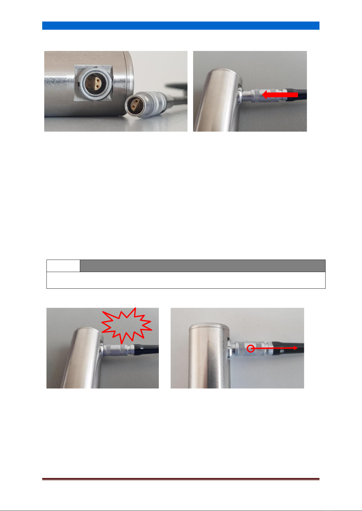
4.2 Connecting and disconnecting the test probe
Shielded connection cables are used to connect the test probes to the SonoDur-R. The contact
arrangement via the above-mentioned half-shell enables the plugging of the connection in one
position only (refer to Figure 4.2)! The silver metal connector on both ends of the cable is a locking
plug-in connector that is based on the push-pull principle: During the plug-in, 3 claws will securely
lock the connector in the socket.
It can only be released by pulling back the outer sleeve of the plug, which will release the locking
claws!
Pin
Signal Name
Description
Voltage Level
1
Vin
Power supply voltage
12-24 VDC
2
---
Not connected
---
3
GND
Ground
0 V
Figure 4.1
i
NOTE!
Note: The power input is reversed voltage protected and filtered.
CAUTION!
The contact arrangement of the connector only allows the plugging to be performed in one
position! Force must be avoided, since the plug system can be damaged!
Preparation for operation
NewSonic SonoDur-R Issue 105 06/2020 Page 11
4.2.1 Connecting the test probe or test device
The silver metal plug shall be carefully pushed into the socket of the test probe while the contact
arrangement allows the connection only in one position. Gently insert and adjust the plug into the
socket without pressure until the plug has reached the correct position and can be easily pushed into
the socket. The locking will be indicated by a 'click'. Afterwards, the plug is firmly locked in the socket
by 3 claws.
4.2.2 Disconnecting the test probe or test device
The silver probe connector can be unlatched by pulling the sleeve back and pulling it out of the
socket, refer to Figure 4.5.
i
NOTE!
The test probe can also be connected after the device was switched on or can be changed during
operation (also refer to the notes in the following sections).
Figure 4.2
Figure 4.3
Figure 4.4
Figure 4.5
Klick!
Switching On and Off
NewSonic SonoDur-R Issue 105 06/2020 Page 12
5Switching On and Off
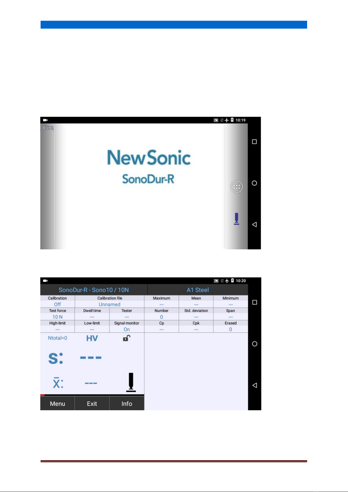
5.1 Power ON
The device is switched on/off via the rocker switch on the rear side of the device (refer to Figure 3.1).
After powering on the instrument, the home screen is displayed after approximately 20 seconds. If a
probe is connected or by tapping on the SonoDur icon the SonoDur program starts (6.1 Start the Test
Program).
Figure 5.1
Figure 5.2
Switching On and Off
NewSonic SonoDur-R Issue 105 06/2020 Page 13
5.2 Switching OFF
Always use the “EXIT”key first to end the SonoDur-R software before switching off the SonoDur-R via
the rocker switch on the rear side of the device.
WARNING
Do not use the switch, before you have finished your measurement and stored all data! Use the
“EXIT” key before switching-off the instrument!
i
NOTE!
If no probe is connected, SonoDur-R starts in simulation mode (6.1.2 Simulation Mode).
In this special operating mode, the instrument will not automatically switch over to regular
measurement mode, if a probe is connected. Please end the program, connect the probe and start
the SonoDur-R application again!

Operating
NewSonic SonoDur-R Issue 105 06/2020 Page 14
6Operating
6.1 Start the Test Program
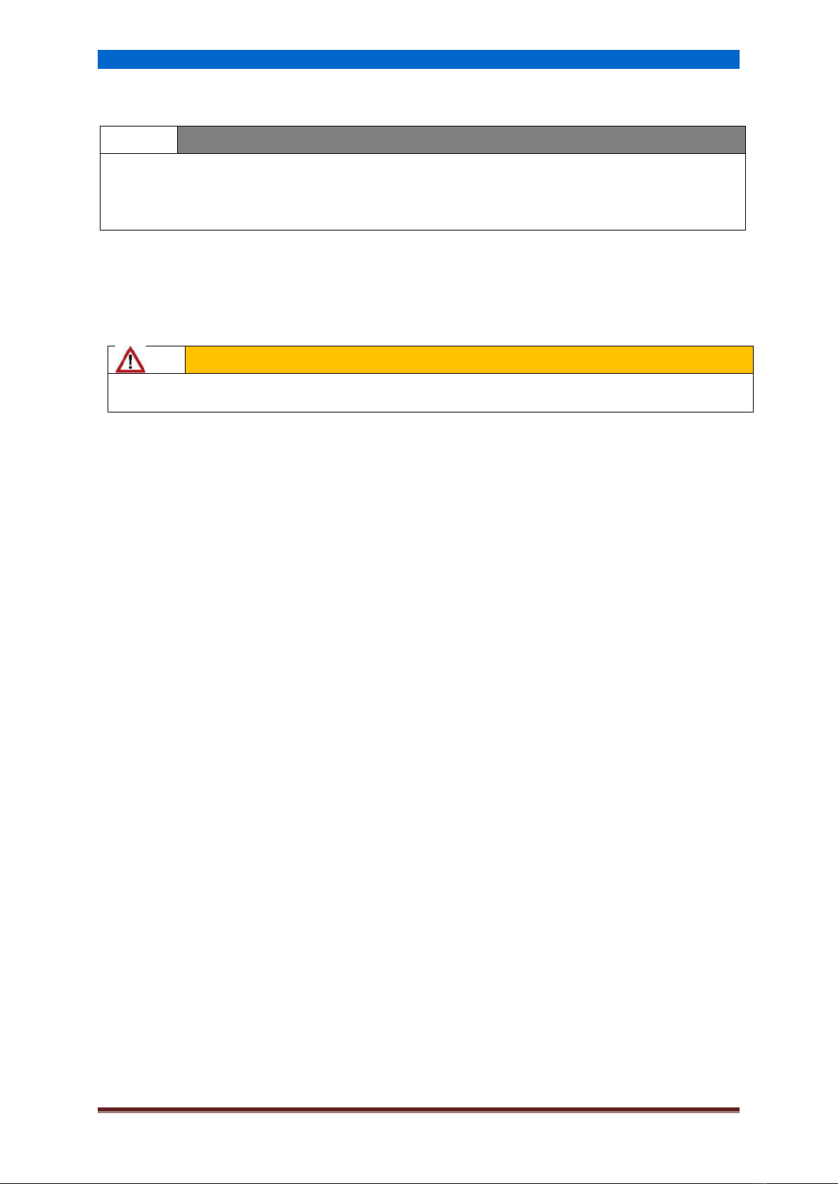
6.1.1 Measuring Menu (Main Menu)
SonoDur-R starts the measuring program automatically if a probe is connected (or changing a probe)
or by touching the SonoDur-R icon and shows the measuring menu (main menu). The probe type and
test force is shown in the upper left corner of the SonoDur-R status line. If no probe is connected or
the probe is not recognized, SonoDur-R starts in simulation mode (6.1.2 Simulation Mode). The
SonoDur-R testing device must be in the "Measure" mode, in order to be able to invoke a
measurement. The "Measurement Menu" can be accessed from any sub menu via the Exit-Button.
Please end all settings or inputs and return to the measuring menu (main menu). The left screen
section contains essential control-, input- and status-fields, the actual measuring value and the mean
value. Ntotal is a counter value and represents the total number of measurements within the actual
measuring set. The right screen area shows statistic information for the selected number of last
measurements, which could be selected from menu -> settings -> max. number of readings N). In the
display there will be always the last N values visible and the statistic is calculated from these last
readings (in this case 10).
6.1.2 Simulation Mode
A special feature of SonoDur-R becomes apparent, when the device is switched on without a probe
being connected: This simulation mode makes it possible to test all functions of the SonoDur
measuring program without having to perform measurements with measuring probes. Starting the
SonoDur program manually without a probe connected, a message box will pop up displaying “No
probe connected. Start program in demo mode?“ Answering “Yes” will start the demo mode.
The demo mode is indicated by showing SonoDur-R - SONO8M (demo) in the status line (Figure 6.3).
"Measurement values" are then created by touching the probe icon (refer to Figure 6.10) and it will
be possible to operate all functions related to the hardness measuring - a special function for fast
operator training and also for demonstrations to interested parties.
Figure 6.1

Operating
NewSonic SonoDur-R Issue 105 06/2020 Page 15
In order to return to the normal measuring mode, the program must be terminated and switched to
measuring mode after a test probe was connected.
Tap the EXIT button, the question Exit Program must be acknowledged with Yes. After connecting a
probe, the measuring program should start automatically.
i
NOTE!
In order to return to the normal measuring mode, the program must be terminated and switched to
measuring mode after a test probe was connected.
Figure 6.2
Figure 6.3

Operating
NewSonic SonoDur-R Issue 105 06/2020 Page 16
6.2 Der Start Screen (Home Screen)
The start screen (Home Screen) shows the status line, the SonoDur-R icon to start the measuring
program and the menu and navigation buttons. The start screen is made of several pages, which can
be reached by wiping on the display to the left/right.
The menu button opens access to all installed applications and settings (refer to Figure 6.6).
i
NOTE!
Application(s) will be called “APP(s)” hereinafter.
Figure 6.4
Nr.
Short abbreviation
Description
1
Status bar
Information on the device status as connections,
power, time.
2
Menu-Button opens the application screen (displays
all installed applications).
3
Navigation buttons
The system is operated via the navigation buttons:
Back
Home, jump to the home screen
(„Home-Button“)
Opens a screen with active
applications
Figure 6.5
Operating
NewSonic SonoDur-R Issue 105 06/2020 Page 17
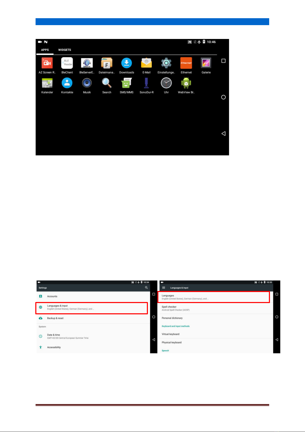
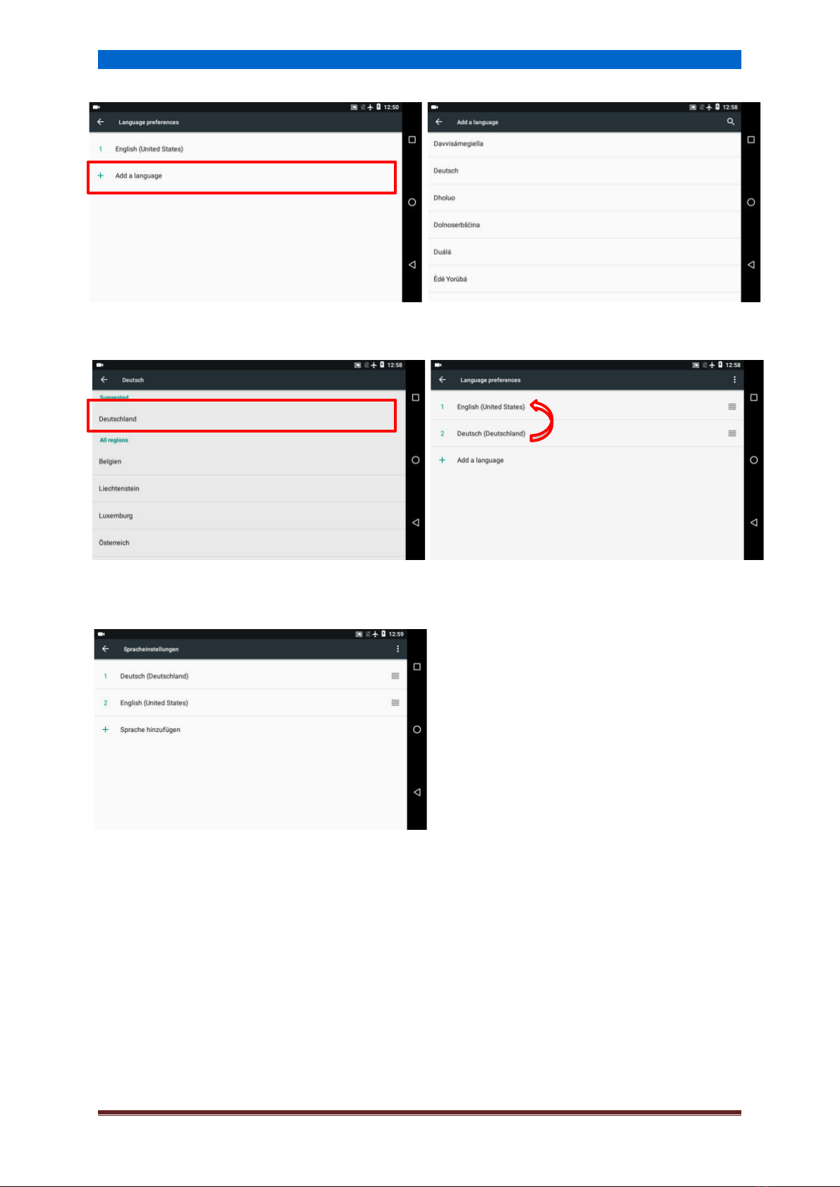
6.3 Change Language
The language can be easily changed via the system settings at any time on-the-fly. Open the
"Settings" menu and select "Language & Input". Select the top entry "Language". A list with all
installed languages will appear. The first item in the list defines the actual language setting. Use “Add
languages” to add additional languages. Tap on “Add language” and select your country language
from the list. This will create a new entry in the last position in the language list.
To make this language active, tap and hold on the line with the desired language and slide to the
topmost (first) entry in the list. The language will change immediately. In this example the
language is changed from English to German (Deutsch).
Restart the SonoDur-R measuring program, all menus and messages will appear in the so selected
country language.
Figure 6.6
Figure 6.7
Figure 6.8
Operating
NewSonic SonoDur-R Issue 105 06/2020 Page 18
Figure 6.9
Figure 6.10
Figure 6.11
Figure 6.12
Figure 6.13
Operating
NewSonic SonoDur-R Issue 105 06/2020 Page 19
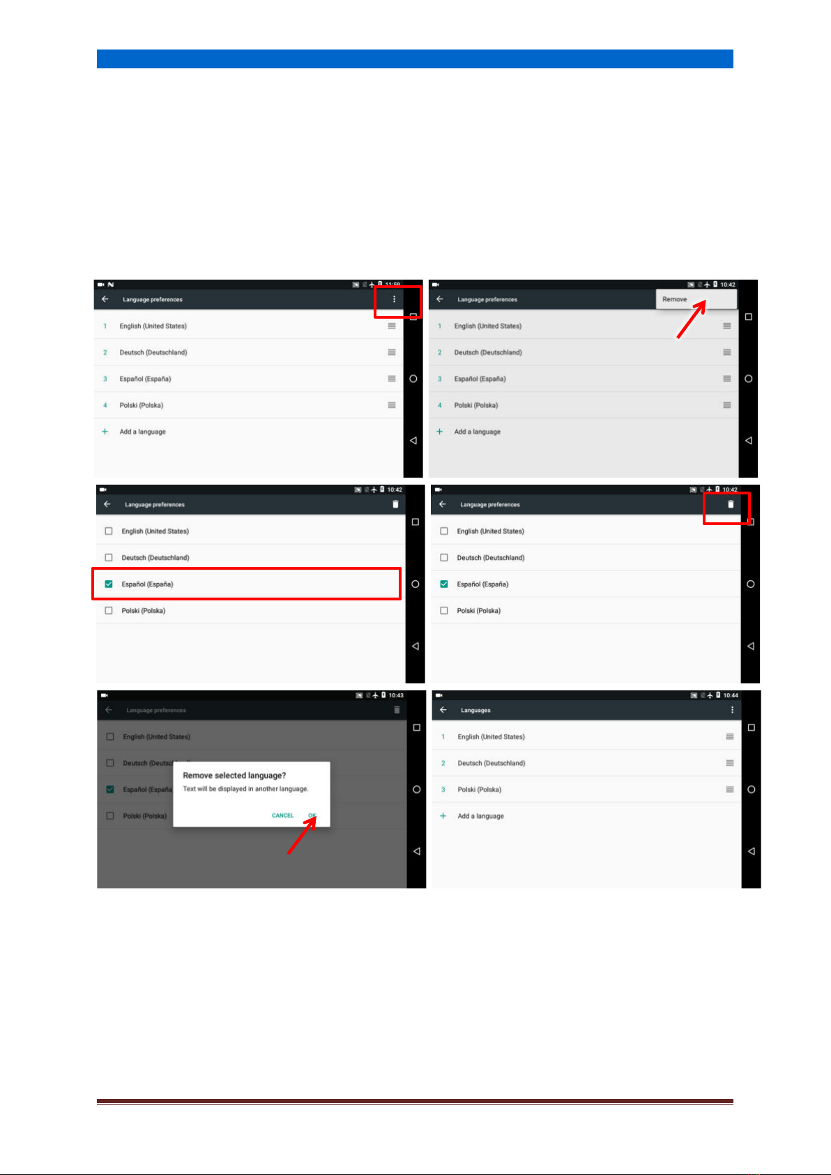
6.3.1 Delete Language
Language entries can be deleted by tapping on the small field in the right upper corner marked with
3 points, it opens a button area “Remove”. Tap on it, all language entries will appear with a blank
check box. Selecting one or more check boxes and tapping on the paper bin symbol will open a menu
“Remove selected language”. By tapping on OK the selected language entries will be deleted from
the list. See following series of photos, in this example the Spanish (Espanol) language is removed.
Figure 6.14
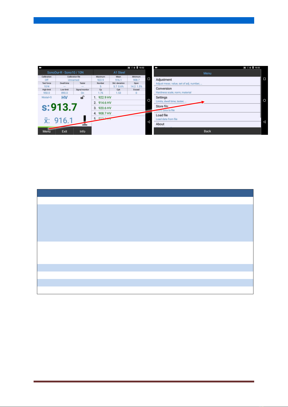
Operation and Menu Structure
NewSonic SonoDur-R Issue 105 06/2020 Page 20
7Operation and Menu Structure
The SonoDur-R is fundamentally operated at two levels, the measurement menu (Figure 7.1) and
the device menu (Figure 7.2).
Figure 7.1
Figure 7.2
7.1 Description of the Operating Elements on the Bottom Menu Bar
The switching between the menus is performed by using the touch-sensitive menu buttons at the
bottom of the display (black keys with white text):
Abbreviation
Meaning
Menu
Switching to the Device Menu.
Exit
1. Leaving the Measurement Menu, End of the measurement series.
2. Leaving any sub-program within the device menu and switching to the
measurement menu.
3. Terminating SonoDur (after processing the last measurement series and
before the first new measured value).
Info
Display of device settings for the measuring process, display of measuring
results such as statistics, individual values and corresponding correction
options.
Back
One step back within the submenu. Cancel
Cancel
Cancelling the current input, one step back.
File
Retrieving and displaying stored measurement data (within the submenu "Info")
OK
Confirming the input and returning
7.2 Buttons –Control Elements (Soft Keys)
Touching the buttons within the "Measurement Menu", allows direct transitions to specific sub-
programs avoiding the search path through the menu branches. After completion of the entry in this
submenu, the return to the starting point will be performed. Touching into the statistic area switches
the presentation graphic -> Zoom -> statistic.
Figure 7.3
This manual suits for next models
1
Table of contents
Popular Test Equipment manuals by other brands


ACS
ACS ALCOLOCK LR troubleshooting manual

Standard Electric Works
Standard Electric Works 6500 LC instruction manual

Tektronix
Tektronix DPO70000C Series user manual

GW Instek
GW Instek MSO-2000EA user manual

Hanna Instruments
Hanna Instruments Groline HI981030 user manual

Megger
Megger VLF CR-40 operating manual


