BERG KOMPBERG ZXF132 Operating instructions

OPERATING AND MAINTENANCE MANUAL
Oil-free screw compressor
KOMPBERG ZXF132

2
Ladies and Gentlemen,
We heartily welcome you among our valued Customers and thank you for your trust to
purchase the BERG compressor.
We are sure you will be fully satisfied with both the choice you have made and the
cooperation you started with us. Our compressors are machines of top quality, which is the
guarantee for a long years and reliable performance.
Our sales and service staff is available to answer all your queries regarding the installation
and operation of your compressor. You are also encouraged to use our warranty and post-
warranty technical service.

3
Table of contents
1. Information concerning the document............................................................................................................4
1.1. Scope and intended use of the manual.......................................................................................................4
1.2. Intended use of the compressor and conditions of safe use ......................................................................4
1.3. Qualification requirements for operation of the compressor.....................................................................5
1.4. Operation ....................................................................................................................................................5
1.5. Other remarks and instructions ..................................................................................................................6
1.6. Warranty .....................................................................................................................................................6
2. Operating safety rules......................................................................................................................................6
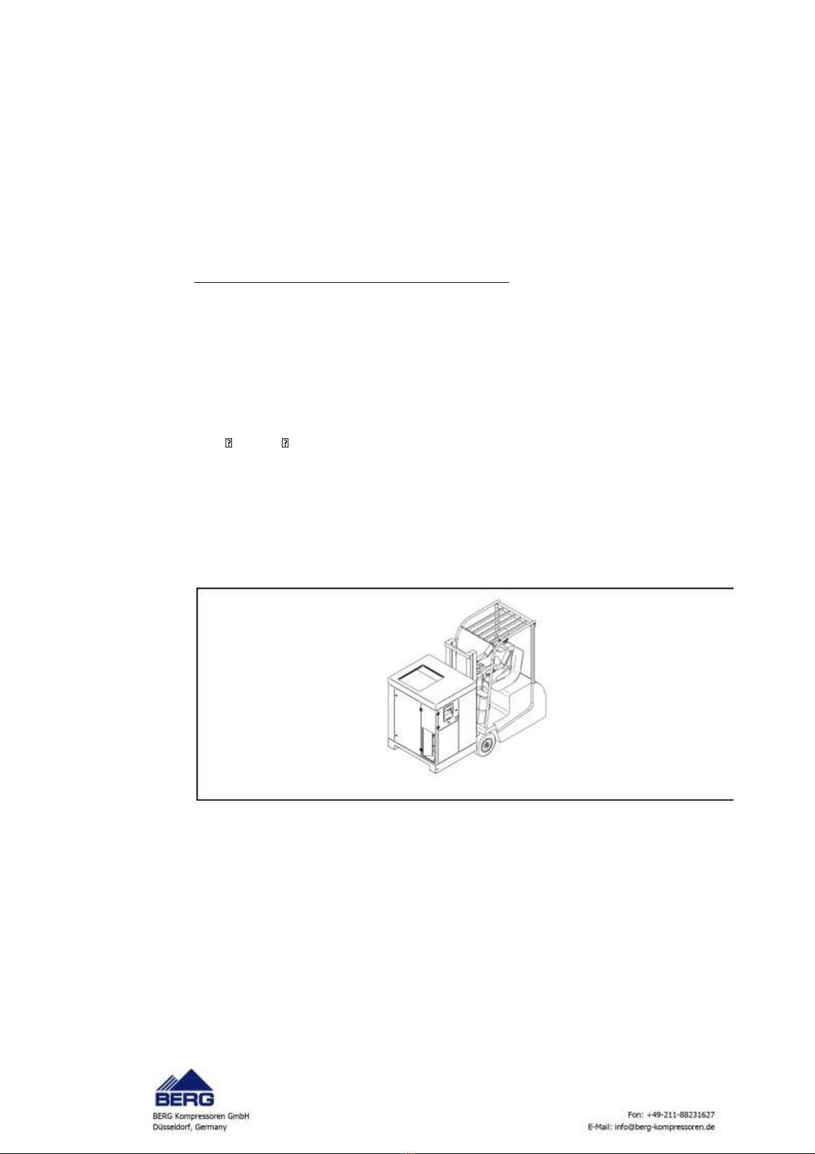
2.1. Basic requirements for safe transport and positioning of the screw compressor ......................................7
2.2. Operating safety requirements ...................................................................................................................7
2.3. Other hazards..............................................................................................................................................8
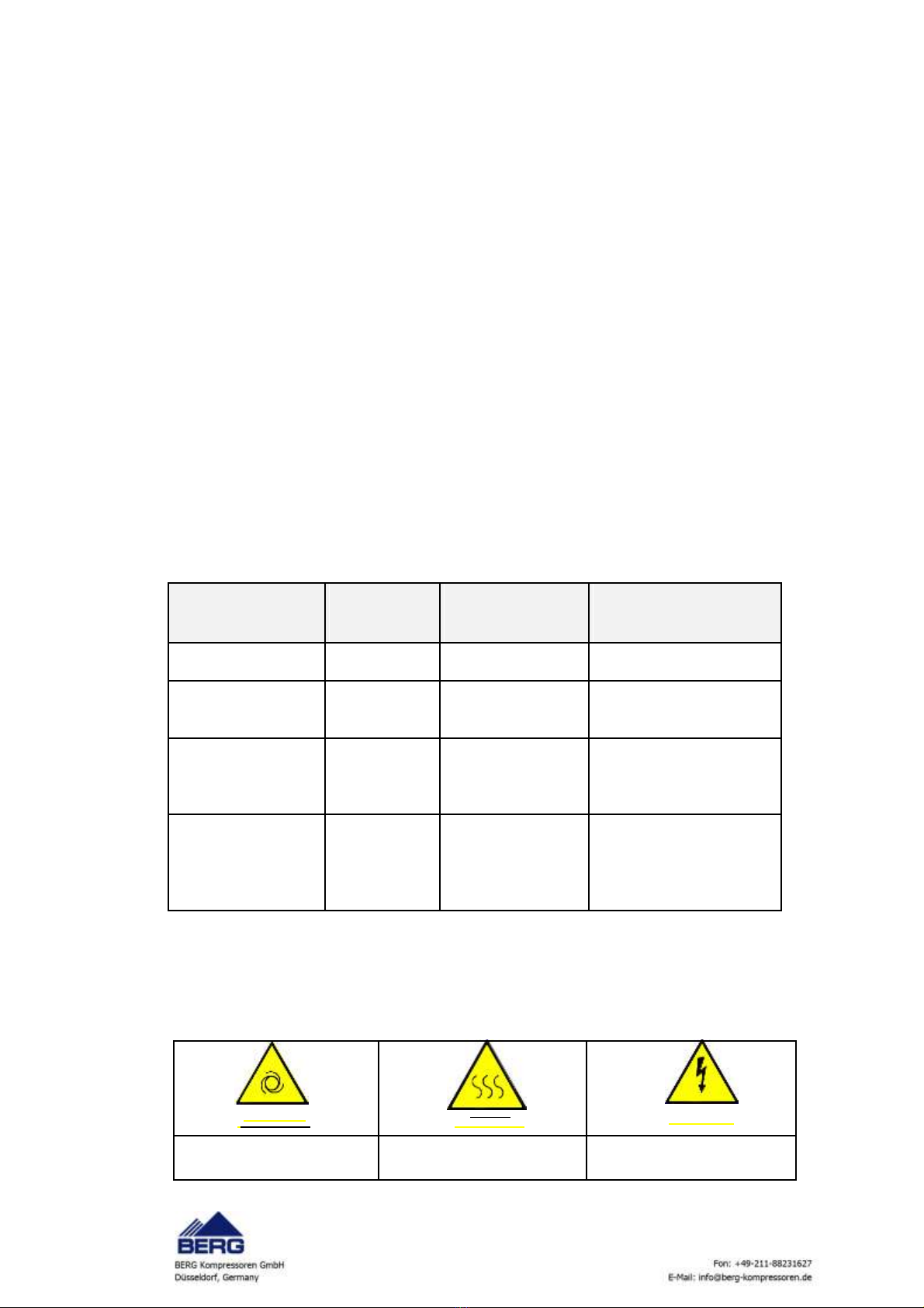
2.4. Meaning of pictograms ...............................................................................................................................8
3. Technical data ................................................................................................................................................9
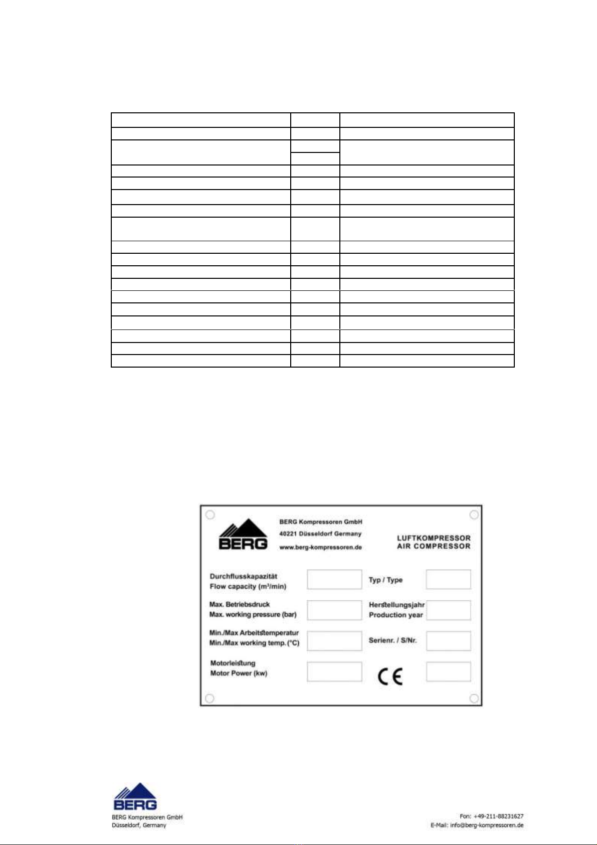
3.1. Identification plate ......................................................................................................................................9
4. Setting........................................................................................................................................................... 10
4.1. Room requirements ................................................................................................................................. 10
4.2. Requirements concerning electrical system ............................................................................................ 11
4.3. Compressed air connection...................................................................................................................... 11
5. Screw compressor operating description and drawings............................................................................... 12
Technological diagram .................................................................................................................................... 19
6. Start-up ......................................................................................................................................................... 22
6.1. Start-up preparation................................................................................................................................. 22
6.2. Restart (after longer downtime) .............................................................................................................. 23
7. Maintenance ................................................................................................................................................. 23
7.1 General requirements ............................................................................................................................... 23
7.2. Maintenance and checks.......................................................................................................................... 24
7.2.1 Maintenance at the beginning of use, after oil and drive belts (if present) change ..........................24
7.2.2 Daily maintenance..............................................................................................................................24
7.2.3 Periodic maintenance ........................................................................................................................24
7.2.4 Warranty and post-warranty checks..................................................................................................25
7.3. Basic components requiring maintenance. Maintenance operations............................................... 25
7.3.1. Air filter cartridge .............................................................................................................................25
7.3.2 Cleaning or replacing the filter mats..................................................................................................26
7.3.3. Oil filter .............................................................................................................................................26
7.3.4. Oil level..............................................................................................................................................27
7.3.5 Changing oil........................................................................................................................................27
7.3.6. Handling wastes produced while operating the compressor ...........................................................28
7.3.7 Oil cooler (exchanger) / interstage / final air .....................................................................................28
7.3.8. . Electric motor..................................................................................................................................29
7.3.9 Safety valve ........................................................................................................................................30
8. Troubleshooting............................................................................................................................................ 30
9. Consumables for one year guarantee........................................................................................................... 33
10. Electrical scheme ........................................................................................................................................ 33

4
1. Information concerning the document
This operating and maintenance manual is an integral part of the machine. It includes the
information necessary to start, operate and maintain the compressor and requirements for its
safe operation.
Following the manual rules will help you:
•Avoid hazards,
•Reduce repair costs and downtime,
•Increase the machine reliability and life.
Getting familiar with this manual in detail, using the machine in accordance with descriptions
included in it and following all safety conditions are the basis for correct and safe operation of
the machine.
In addition to the operating and maintenance manual and the regulations applied in the country
of destination and health and safety at work regulations applied locally at the workstation, the
generally recognised technical rules for safe and correct work are also valid.
1.1. Scope and intended use of the manual
The operating and maintenance manual is intended for qualified / suitably trained operating
personnel of the compressor. The personnel assigned to operation of the compressor must,
before starting work, get familiar with the manual contents, in particular the “Health and safety
at work regulations” section.
The manual includes
•Description of daily service and maintenance of the compressor and control system,
•Technical documentation of the electrical part. It includes the data necessary to perform correct
connections and repairs of the electrical equipment,
•Technical documentation of the mechanical part. It includes the data necessary to perform
repairs of the mechanical equipment,
•Technical documentation of the control system. It includes the data necessary to switch on and
off, and set operating parameters of the compressor.
The qualified personnel is understood to be the persons who because of received training,
experience and knowledge of important standards, documentation and regulations concerning
safety and operating conditions were authorised to carry out necessary operations and are able
to recognise and avoid possible hazards.
1.2. Intended use of the compressor and conditions of safe use
The compressor is designed to produce only compressed air. It should be installed in accordance
with the stipulations concerning the compressor installation and connection. The compressor
must not be used for any other purposes that are non-compliant with its intended use.The
manufacturer shall not be liable for any damage resulting from that reason.In that case, the risk is
born by the machine user only.
During the compressor operation, you must follow the procedures given in the “Maintenance”
section as regards scope and frequency of maintenance work and materials to be used.

5
Warning bout forbidden use
•The compressor must not be used for any other purposes that are non-compliant with its intended use.
•Under no circumstances must the limit operating parameters of the compressor be exceeded and changed -
refer to section 10 "Technical data".
•To use it for compression of other gases than air, it is required to obtain the manufacturer’s consent. The
above consent must be in written form.
•The compressor must not be used in potentially explosive atmospheres within the meaning of Directive
2014/34/UE.
•The compressor must not suck any toxic, acid-containing, flammable or explosive gases and vapours.
•Never direct a jet of compressed air at people or animals.
Safe use of the compressor
•The compressor must be operated in accordance with all guidelines included in this operating and
maintenance manual.
•The sucked air must be clean and must not contain any harmful substances.
•The heated cooling air may be used for heating purposes if only its harmfulness to people and animals is
excluded. Otherwise, it is necessary to provide the appropriate treatment of cooling air.
•Compressed air may only be used for breathing after its appropriate treatment.
•Compressed air not subjected to the appropriate treatment must not be used in production processes in
which there is contact of air with food.
The compressor delivered is designed to compress only air.To use it for compression of other gases, it is
required to obtain the manufacturer’s consent. The above consent must be in written form. The
compressor must not be used for any other purposes that are non-compliant with its intended use.
Fulfil the obligation to register the compressor air receiver in the Office of Technical Inspection
(UDT).The compressor documentation is accompanied by the set of the required documentation
of the air receiver (if applicable) and safety valve.
1.3. Qualification requirements for operation of the compressor.
The personnel who installs, operates and maintains the compressor should have the appropriate
education and qualifications enabling safe operation of electrotechnical and electrical
equipment.
Installation, operation and maintenance of the compressor may only be carried out by the
persons who are familiar with this operating and maintenance manual, follow instructions
included in it, know safety regulations and recognised technical rules.
1.4. Operation
While operating the compressor:
-Observe the instructions provided in the Operating and Maintenance Manual and Warranty Book.
-Follow the periodic inspection schedule during both warranty period and after its completion.
Regular performance of periodic inspections is necessary to ensure the required reliability and life
of the BERG equipment. The inspections performed according the schedule reduce the number of
repairs and their cost.
-The technical and operating inspections should be carried out in accordance with the schedule
and conditions by the factory service or authorised service, using the manufacturer’s consumables
and spare parts.
-During the warranty period, use only the manufacturer’s consumables and spare parts.
The detailed list of maintenance operations can be found in the "Maintenance and
inspections" section.

6
1.5. Other remarks and instructions
-This Operating and Maintenance Manual provides all information on how to install, start and operate the
compressor. This manual should also be used when any maintenance work is carried out,
-The Manual should be read and always available to the compressor operator,
-During the maintenance work and periodic inspections, the provisions of the Warranty Book should be
observed,
-The Maintenance section provides all measures and requirements necessary to keep the compressor in a
correct technical state,
-Record all operating data, maintenance operations performed etc. into the Warranty Book. Observe all
reference and local safety regulations relating to the compressor, including those listed herein and in the
following sections,
-Failure to follow the requirements included in this Operating and Maintenance Manual and Warranty
Book and/or unauthorised changes in the compressor or its integral units delivered by us shall make the
warranty null and void.
-During warranty period, any repairs must be performed by the manufacturer service or authorised
service centre listed in the Warranty Book.
1.6. Warranty
BERG Kompressoren GmbH. Speddition Straße 21, 40221 Düsseldorf Germany hereinafter referred to
as the Warrantor provides the warranty for the products sold, ensures correct operation of the offered
products provided that they are used in accordance with their intended use and operating conditions
specified in this documentation.
The Purchaser shall lose its warranty rights for the product when:
-The machine is used in a way non-compliant with its intended use,
-Unauthorised modifications are carried out on the product,
-Interventions are carried out by unauthorised persons,
-Any repair attempts are carried out by unauthorised persons,
-The obligation to carry out periodic inspections is not observed,
-Non-original consumables are used.
The manufacturer reserves the right to make modifications in the product, resulting
from continuous technical development, without prior notice.
2. Operating safety rules
The present rules are valid for BERG screw compressors. In addition to the general health and
safety at work andthe Office of Technical Inspection (UDT) regulations applicable to compressors,
their assemblies and accessories, the safety instructions given below should be followed in
particular. The operators are supposed to observe safe work practices. It is the user’s
responsibility to continuously maintain the compressor fully operable. Components and
equipment considered to be no longer suitable for safe operation should be promptly replaced.
Adjustments, installation, operation, maintenance and servicing should be entrusted only to
properly trained, qualified and authorized staff.
The limit values (pressure, temperature, time settings etc.) are given in the Technical Data
section.
The limit values may not be changed by the user.
The manufacturer accepts no responsibility for any personal injuries, damage of equipment or
the compressor itself, at present and in the future, resulting from user’s negligence and failure to
observe the installation, operation and maintenance requirements contained herein. No
responsibility is also taken for failure to observe valid safety standards relating to the equipment
and qualified staff.

7
2.1. Basic requirements for safe transport and positioning of the screw compressor
In addition to the general health and safety at work and the Office of Technical Inspection (UDT)
regulations, the following rules must be observed:
-Use only the lifting equipment that is compliant with the H&S and UDT regulations to lift the
compressor. Fix in place all rotating or loose parts of the machine before its lifting. It is strictly
forbidden to stay in the hazardous zone of the lifting equipment operation. The compressor
movement can be accelerated or slowed down only within the permissible limits.
-When the compressor is transported, the transport straps should be pulled under the machine
and secured above the housing in such a way that they do not place pressure on it. If the
transport harness is fastened and secured incorrectly, the machine may get damaged.
-The compressor must be transported only with a forklift.
-Fasten the compressor frame with cargo straps to appropriate holders on the vehicle platform to
prevent it from sliding or overturning.
-All screw and pipe connections should be of appropriate size and designed for a given operating
pressure.
-The compressor is not designed to operate outdoors; it cannot be exposed to weather
conditions.
-The compressor should be positioned in a closed room, where ambient air is cool and clean.
Never block air flow to and from the room. Ensure sufficient inflow of cooling air and discharge of
hot air outside the room. Temperature in a room with the compressor should be within the range
of + 5 C to + 40 C.
-The air sucked in should contain no vapours or flammable gases, e.g. paint thinners, that might
cause internal fire.
-There can be no objects close to the air inlet that could be sucked in with a jet of air.
-The pressure conduit connecting the compressor with the compressed air line should allow free
expansion due to generated heat. It must not touch hot objects or flammable materials.
The detailed requirements concerning the machine positioning in the compressor room are
described in section 4.1.
Transport of the machine with a forklift.
2.2. Operating safety requirements
In addition to the requirements contained in the sections: Screw compressor operation description; Start
up; Maintenance; the following rules should be observed.
-The compressor is only designed to compress air.
-All safety equipment must be in place while operating the machine.
-The factory-mounted safety equipment must not be removed. Please, remember to remove any transport
brackets (if applicable)before first start-up of the compressor. The transport brackets are only used to
protect the machine during transport.
-There are hot parts in the compressor e.g. conduits, air and oil coolers, screw block. They will scald when
touched.
-No unauthorized modifications in the control system are allowed. After power failure, the compressor
must be restarted when the power supply is recovered.

8
-It is prohibited to remove the green and yellow protective conductors that prevent electric shock.
-No additional equipment can be mounted on the air receiver(except for the equipment allowed for use by
the manufacturer).
-No welding operations or any other repairs can be performed on the air receiver.
-The plugs and other air receiver accessories can only be removed after the air receiver depressurisation
to the ambient pressure.
-General safety rules should be observed while depressurising the air receiver. Air must be vented slowly.
Keep the air stream away from people.
-Do not allow oil spill around the compressor.
-It is strictly prohibited to service the safety valves or to change their settings.
-Do not change settings of the pressure switches above the value given in the identification plate or in the
Operating and Maintenance Manual.
-Fulfil the obligation to register the compressor air receiver in the Office of Technical Inspection (UDT).
Two sets of the required documents of the air tank (if provided) and safety valve are included with the
compressor documentation. The compressor documentation is accompanied by the set of the required
documentation of the air receiver (if applicable) and safety valve.
-Do not remove the temperature sensor (transmitter) or pressure transmitter.
2.3. Other hazards
The compressor installation, switching on/off and maintenance must be carried out by the
qualified personnel who strictly follows the data included in the product technical documentation
and safety rules to avoid any hazards. The risks that could not have been eliminated during the
design stage are described in the table below.
Unit
Residual risk
Action
Precautions
water cooler, frame
minor cuts
touching
avoid touching, wear
protective gloves
screw assembly,
danger of
avoid touching, wear
end cooler, pressure
touching
scalds
protective gloves
conduits
damage of wire
adequate guard for the
metallic parts and
electric shock
insulation upstream
power supply lead; check
electric wire
the motor breaker,
the wire insulation for
live metallic parts
damages
fire due to shorting
use the cross section of
around the
danger of
or overheating of
the power cord and the
the power cord
protection corresponding
compressor
scalds
before the electrical
to the applicable
box
standards
2.4. Meaning of pictograms
Pictograms (safety symbols) located on and inside the compressor are described below.
Explanation is provided below any of them.
For technical reasons, it is not always possible to attach the pictograms in the very vicinity of the points of
risk.
AUTOMATIC MACHINERY
RISK OF SCALDING
RISK OF ELECTRIC
MAY START
SHOCK

9
3. Technical data
Type
KOMPBERG ZXF132
Overpressure*
MPa
1,0
Min ÷ Max capacity
m
3
/h
440 ÷ 1143
m
3
/min
7,33 ÷ 19,05
Weight
kg
4500 kg
Dimensions (LxWxH)
mm
3400x2100x2400
Compressed air connection
G3
Ambient temperature
0C
+5 ÷ +40
0
C
Compressed air temperature
0
C
+10 do 15
0
C above ambient
temperature
Noiselevel L**
DB(A)
85
Screw air-end type
CD14D1
Max oiltemperature
0C
70
Nominal motor power
kW
132
Nominal motor rotary speed
rpm
3000
Supply voltage
400V/50Hz/3ph
Nominal fan motor power
kW
11
Cooling air requirement
m
3
/h
19500
Power lead cross sectional area
mm
2
3x150+PE
Protection
A
315
*)
- Capacity measured acc. to EN ISO 1217: 2006 and EN ISO 5167-2.
**)
- Noise level acc. to EN ISO 2151.
-Momentary value of acoustic pressure corrected by C characteristic does not exceed 130dB.
-Equivalent acoustic pressure level corrected by A characteristic does not exceed 85 db(A).
3.1. Identification plate
The identification plate as shown below is attached to the compressor housing or frame. When
contacting us regarding your compressor, please provide the data given on the identification
plate: compressor type, year of manufacture and factory number.

10
4. Setting
4.1. Room requirements
-The compressor requires no foundations. It must be positioned on a hard and even surface. Take into
consideration the floor load capacity, if the machine is installed in a building.
-Strictly observe the minimum distances from walls and other machines. When several
compressors are installed, pay attention to the direction of cooling air flow; no compressor
should suck air which is heated by other machine. Minimum distances from the room walls and
other objects are given in the drawings below.
-Protect the room in which the compressor is installed from negative temperatures. The inlets
and outlets to and from the room should be located in such a manner to protect the interior
from weather conditions.
-Heat generated during compression should be extracted outside (or to other rooms), and fresh
air should be supplied from the outside.
-If the gravity ventilation is insufficient (windows, openings in a wall etc.) in the compressor room,
air exchange should be provided by fans. To ensure correct heat extraction, the fans should have
total capacity about 15 to 20% higher than the total cooling air requirement for all compressors
installed in the room. The required cooling air volume is specified in the Technical Data section.
-Ambient temperature in the room should be from + 5 C to +40 C.
-Provide sufficient room for maintenance operations.
-It is necessary to consult our specialists when you want to install a duct supplying air from the
outside or use air for heating the rooms.
-The compressor room should be well lighted to ensure trouble-free and safe service of the
equipment.
-To improve ventilation in the compressor room, the machine can be connected to the discharge
air duct; in such case, please contact BERG.
The suitable ventilation in a room will prevent the possibility of negative pressure generation or
undesired temperature increase.
When there are any problems in ensuring the suitable ventilation in a room, please contact
BERG.

11
4.2. Requirements concerning electrical system
-The compressors are designed to be supplied by a four-conductor 400 V AC, 50 Hz power line.
-The compressors are equipped with PE terminal.
No.
Cmpressor type
Power lead cross
Fuse size
NH gL/gG, 500V, 100kA
sectional area
D gL/gG, 500V, 50kA
mm
2
1
KOMPBERG
3x150mm2+PE
315
ZXF132
Recommended power cable cross sectional area and fuse sizes
-The power cable cross sectional area should be matched to the current drawn by the
compressor.
-The compressors can only be operated onthree-phase earthed system (TN).
-The compressor must be supplied from the distribution board equipped with a slow blow
fuse and circuit-breaker that enables the compressor power supply to be completely
disconnected.
-Electrical connection of the compressor should be performed in accordance with the
attached electrical diagram.
-Only authorised personnel or qualified electrician is allowed to perform electrical
connections.
-Use the required safety measures in accordance with the suitable regulations.
-Calculate the power cable cross sectional area and fuse sizes according to the local
regulations and operating conditions.
-Below there are presented the recommended power cable cross sectional areas and fuse
sizes for standard compressors.
-A user takes a full responsibility for selection of an electrical system and power supply
connection for the compressor.
4.3. Compressed air connection
It is recommended to use galvanized steel or plastic tubes for the compressed air system.
When the compressed air treatment equipment (filters, dryer) is installed, the existing
compressed air piping should be replaced with a new one, unless air supplied previously
was treated by similar equipment.
Each BERG compressor should be connected to the compressed air network by using a
flexible conduit or flexible connector (axial expansion joint) and shut-off valve.
Elbow
Pneumatic
hose
Compressed air outlet

12
5. Screw compressor operating description and drawings
1
Air filter
29
Pressure sensor
2
Suction valve
30
Temperature sensor
3
First stage
31
Temperature sensor
4
Venturi nozzle
32
Temperature sensor
5
First stage cooler
33
Safety valve
6
Cyclone separator
34
Pressure sensor
7
Second stage
35
Temperature sensor
8
Venturi nozzle
36
Pressure sensor
9
Second stage cooler
37
Manometer
10
Check valve
38
Main motor
11
Unloading valve
39
Fan motor
12
Silencer
40
Fan
13
Oil sight glass
41
Shock absorber
14
Oil tank
42
Oil drain
15
Oil pump
43
Oil inlet
16
Thermostatic valve
44
Coupling
17
Solenoid valve
43
Oil inlet
18
Oil cooler
44
Coupling
19
Oil filter
45
Housing
20
Overflow valve
46
Frame
21
Oil manifold
47
Cooling air inlet
22
Vent filter
48
Air end
23
Hydraulic cylinder
49
Inlet valve
24
Solenoid valve
50
Compressed air outlet
25
Solenoid valve
51
Controller
26
Air filter pollution sensor
52
Emergency switch
27
Temperature sensor
53
Frequency converter
28
Safety valve

13

14

15

16

17

18
The compressor is equipped with two stage air end ("of dry-type") without oil injection into the
compression chamber with the bearings and gearing and the coat of the high pressure part are
lubricated and cooled with oil.
POWER AND CONTROL
The compressor (screw air-end) is driven by an electric motor through a flexible coupling .
Control of the entire electrical system is placed in a electrical box.
AIR CIRCULATION
The air is sucked through the air filter (1) and the suction controller (2) to the air end’s first stage
(3). The compressor suction regulator is equipped with a second stage discharge valve (11) and a
noise damper (12). After compression to the overpressure of up to 0,35 MPa the air is forced from
the 1st stage to the intercooler (5). After cooling in the cooler, the air flows through the cyclone
separator (6) and is sucked to the second stage (7). First stage compression and internal system
are protected against pressure rise above the permissible value by a safety valve (28). After
compression, it reaches an overpressure of up to nominal value and is forced into the end cooler
(9), and then through the check valve (10) to the compressor outlet.
OIL SYSTEM
The oil is sucked by the pump (15) from the oil tank (14) and is forced to the oil filter (19) set
fitted with a thermostat (16) which, depending on the oil temperature, directs the oil directly
through the oil filter (19) to the overflow valve (20) and manifold (21) or at temperature
exceeding 55 ° C to the oil cooler (18) and then through oil filter (19) to the manifold (21). The
pressure in the manifold is limited to 0.14-0.16 MPa with an overflow valve (20). The outlets from
the oil filter assembly to the oil cooler and inlet from the radiator to the unit are equipped with
electromagnetic shut off valves (17) and (17) which are closed (normally closed NZ) when in the
de-energized condition. These valves are designed to prevent the flow of oil from the radiator to
the installation and further to the oil tank, which avoids the need to always fill the radiator with
oil after the compressor's standstill. In addition, the oil level display in the sight glass (13) is
always reliable (without shut off valves the sight glass would be completely filled with oil)
overflow valve (20) in which the oil overpressure is limited to 0.25-0.30 MPa.
From the manifold the oil is distributed to both compression stages ie bearings, seals and coats of
I-stage and II- stage. After passing through the compressor, the oil flows to its tank (14).
After the filter, the oil is also fed to the three-way valve (24) and, depending on the compressor
load, flows to the hydraulic cylinder (23) controlling the shutter (11) in the suction controller (2).
In the second position, the oil from the valve (24) flows to the compressor tank (14). Also the oil
from the hydraulic cylinder is directed to the compressor tank.

19
Technological diagram
1
Air filter
19
Oil filter
2
Suction valve
20
Overflow valve
3
First stage
21
Oil manifold
4
Venturi nozzle
22
Vent filter
5
First satage cooler
23
Hydraulic cylinder
6
Cyclone separator
24
Solenoid valve
7
Second stage
25
Solenoid valve
8
Venturi nozzle
26
Air filter pollution sensor
9
Second stage cooler
27
Temperature sensor
10
Check valve
28
Safety valve
11
Unloading valve
29
Pressure sensor
12
Silencer
30
Temperature sensor
13
Oil sight glass
31
Temperature sensor
14
Oil tank
32
Temperature sensor
15
Oil pump
33
Safety valve
16
Thermostatic valve
34
Pressure sensor
17
Solenoid valve
35
Temperature sensor
18
Oil cooler
36
Pressure sensor
37
Manometer

20
MEASURING SENSORS
The following temperature sensors and pressure transducer are installed in the compressor installation:
(26) - air filter pollution sensor,
(27) - temperature sensor - realizes the measurement of the compressed air temperature after the I stage (3),
(30) - temperature sensor - realizes the measurement of the compressed air temperature after cooling in the
cooler (5),
(29) - pressure transducer - performs measurement of air pressure after the cooler (5),
(31) - temperature sensor - realizes air temperature measurement after the II stage (8),
(32)- temperature sensor - realizes air temperature measurement after the radiator (9),
(34) - pressure transducer - performs the measurement of compressed air pressure after the cooler, after the
check valve,
(35) - temperature sensor - performs measurement of oil temperature,
(36) - pressure transducer - performs oil pressure measurement.
These sensors and transducers work with the PLC.
WATER CONDENSATE DRAIN
Water in the compressor airsystem means a very high risk of failure, including the screw air end failure. This is
why the water condensate from the air is carefully drained in the compressor. The condensate from the
separator (6) after the intercooler (5) is drained out of the compressor by float operated mechanical condensate
drain (25).
VENTILATION OF THE SCREW AIR-END INSIDE
During operation of the compressor in the spaces in the interior of its bodies, bearing housings and seals a small
overpressure is produced. This is detrimental to the correctness of the lubrication and sealing processes.
Therefore, these spaces must be ventilated. This is accomplished by means of a flexible hose and an air filter
located at the tunnel of the fan; In the figure it is marked with a symbol (22).
COMPRESSOR COOLING
The compressor is cooled in a forced manner by means of a fan with its own electric drive. The air is sucked in
through the inlets on the front and rear wall of the housing and pushed through a set of radiators placed on top
of the compressor and thrown outside the compressor.
OPERATION OF THE OIL FREE COMPRESSOR
The compressor is started by pressing the START button on the control panel. After the button is pressed, the
compressor drive is activated. The compressor is designed for intermittent run. The intermittent operation
involves air pressurisation until the maximum overpressure set on the pressure switch is reached.
When this pressure is reached, the compressor switches to idle running (the hydraulic actuator closes the air supply
on the compressor suction side) and then there is a countdown of the time to stop. If during this time the air pressure
decreases, the compressor will start again, and if not, it will shut down after the countdown. The compressor is
restarted when the overpressure in the piping drops to the minimum value set in the controller.
The compressor can be stopped at any time by pressing the STOP button on the controller panel.
The operation is resumed by pressing the START button.
When the overpressure in the piping on the compressor start exceeds the value set in the pressure switch, the
compressor will start only after the overpressure drops to the minimum value.
After stopping the compressor with the EMERGENCY STOP (STOP AWARYJNY) button and after the supply
voltage is switched off and on, the compressor can be started by unlatching the EMERGENCY STOP (STOP
AWARYJNY) button and pressing the START button.
The compressor is provided with an additional protective function which prevents machine start when any of
parameters given in Tab.[Technical data] is exceeded.
Table of contents
Other BERG Air Compressor manuals