Bergoz MX-BPM User manual

bergoz
Instrumentation
Bergoz Instrumentation
Espace Allondon Ouest
01630 Saint Genis Pouilly, France
Tel.: +33-450.426.642
Fax: +33-450.426.643
Rev. 1.5.4
Japan:
U.S.A.:
REPIC Corporation
GMW Associates
28-3, Kita Otsuka 1-Chome
955 Industrial Road
Toshima-ku, Tokyo 170-0004 San Carlos, CA 94070
Tel.: 03 - 3918 - 5326 Tel.: (650) 802-8292
Fax: 03 - 3918 - 5712 Fax: (650) 802-8298
BERGOZ Instrumentation - 01630 Saint Genis Pouilly, France - Tel.: +33-450.426.642 - Fax: +33-450.426.643
email: [email protected] - http://www.bergoz.com - Registre des Métiers: Bourg-en-Bresse - Registre des ingénieurs: Zurich
TVA-VAT-IVA-USt. Nº FR88414997130 - Sàrl. capital 152K
- Siren 414 997 130 R.C.S. Bourg - APE 332B
Multiplexed
Beam Position Monitor
User’s Manual
Visit our web site at
http://www.bergoz.com


SUMMARY
Page
INITIAL INSPECTION
.................................................................
2
WARRANTY
.............................................................................
2
ASSISTANCE
...........................................................................
2
SERVICE & RETURN PROCEDURES
.............................................
2
YOU JUST RECEIVED A BPM POSITION MONITOR...
.......................
3
QUICK CHECK
.........................................................................
3
ON-BOARD ATTENUATORS ADJUSTMENT
......................................
6
Beam Position Monitor board
..................................................
7
BUTTON SAMPLING
....................................................................
7
EXTERNAL CLOCK
.....................................................................
8
ALGORITHM & POLARITY CONVENTION
........................................
8
PRINCIPLE OF OPERATION
...........................................................
9
BLOCK DIAGRAM
.......................................................................
9
PERFORMANCE
..........................................................................
10
Sampling frequency
.............................................................
10
Noise (resolution)
................................................................
10
Position (linearity) error
.........................................................
11
Drift
................................................................................
12
CLOSE ORBIT OPERATING MODE
..................................................
13
FIRST TURN CAPABILITY
............................................................
14
Single Button Sampling (SBS) option
........................................
14
SINGLE BUNCH / SINGLE BEAM OPERATION
..................................
16
Fast NIM Gate (FG) option
....................................................
16
X AND Y GAIN ADJUSTMENT
.......................................................
18
LOCAL OSCILLATOR PROGRAMMING
............................................
20
SIGNALS
...................................................................................
22
CABLES LAYOUT, INSTALLATION
.................................................
25
OPERATING CONSIDERATIONS
.....................................................
26
Aliasing of AM and FM modulations
..........................................
26
Identifying and eliminating aliasing
............................................
26
CONNECTORS PINS ALLOCATION
.................................................
28
ACCESSORIES
............................................................................
29
Table-top test kit
.................................................................
29
Card extender
.....................................................................
30
Service modules, TTL commands, RF
........................................
30
Chassis
............................................................................
31
SPECIFICATIONS
........................................................................
32
BPM MODULE REAR CONNECTOR
.................................................
33
SCHEMATICS & BOARD LAYOUT
...................................................
34
ACKNOWLEDGEMENT
.................................................................
34
Annex I.
RF Connectors from Siemens
Annex II.
Precision Analog Signal Processing for Beam Position Measurements in Electron
Storage Rings, J.A. Hinkson and K.B. Unser, Proceedings of the 2nd DIPAC,
Travemünde 1995
Annex III.
New Generation Electronics Applied to Beam Position Monitors, Klaus B. Unser
1996 Beam Instrumentation Workshop, Argonne National Laboratory.
BERGOZ Instrumentation
Multiplexed
01630 Saint Genis Pouilly, France
Beam Position Monitor
Tel. +33-450.426.642
Fax +33-450.426.643
Page 1 User’s manual
BERGOZ Instrumentation - 01630 Saint Genis Pouilly, France - Tel.: +33-450.426.642 - Fax: +33-450.426.643
email: [email protected] - http://www.bergoz.com - Registre des Métiers: Bourg-en-Bresse - Registre des ingénieurs: Zurich
TVA-VAT-IVA-USt. Nº FR88414997130 - Sàrl. capital 152K
- Siren 414 997 130 R.C.S. Bourg - APE 332B

INITIAL INSPECTION
It is recommended that the shipment be inspected immediately upon delivery. If it is damaged in any
way, contact Bergoz Instrumentation or your local distributor. The content of the shipment should be
compared to the items listed on the invoice. Any discrepancy should be notified to Bergoz
Instrumentation or its local distributor immediately. Unless promptly notified, Bergoz
Instrumentation will not be responsible for such discrepancies.
WARRANTY
Bergoz Instrumentation warrants its beam monitors to operate within specifications under normal use
for a period of 12 months from the date of shipment. Spares, repairs and replacement parts are
warranted for 90 days. Products not manufactured by Bergoz Instrumentation are covered solely by
the warranty of the original manufacturer. In exercising this warranty, Bergoz Instrumentation will
repair, or at its option, replace any product returned to Bergoz Instrumentation or its local distributor
within the warranty period, provided that the warrantor's examination discloses that the product is
defective due to workmanship or materials and that the defect has not been caused by misuse, neglect,
accident or abnormal conditions or operations. Damages caused by ionizing radiations are specifically
excluded from the warranty. Bergoz Instrumentation and its local distributors shall not be responsible
for any consequential, incidental or special damages.
ASSISTANCE
Assistance in installation, use or calibration of Bergoz Instrumentation beam monitors is available
from Bergoz Instrumentation, 01630 Saint Genis Pouilly, France. It is recommended to send a
detailed description of the problem by fax.
SERVICE PROCEDURE
Products requiring maintenance should be returned to Bergoz Instrumentation or its local distributor.
Bergoz Instrumentation will repair or replace any product under warranty at no charge. The purchaser
is only responsible for transportation charges.
For products in need of repair after the warranty period, the customer must provide a purchase order
before repairs can be initiated. Bergoz Instrumentation can issue fixed price quotations for most
repairs. However, depending on the damage, it may be necessary to return the equipment to Bergoz
Instrumentation to assess the cost of repair.
RETURN PROCEDURE
All products returned for repair should include a detailed description of the defect or failure, name and
fax number of the user. Contact Bergoz Instrumentation or your local distributor to determine where
to return the product. Returns must be notified by fax prior to shipment.
Return should be made prepaid. Bergoz Instrumentation will not accept freight-collect shipment.
Shipment should be made via Federal Express or United Parcel Service. Within Europe, the
transportation service offered by the Post Offices "EMS" (Chronopost, Datapost, etc.) can be used.
The delivery charges or customs clearance charges arising from the use of other carriers will be
charged to the customer.
BERGOZ Instrumentation
Multiplexed
01630 Saint Genis Pouilly, France
Beam Position Monitor
Tel. +33-450.426.642
Fax +33-450.426.643
Page 2 User’s manual
BERGOZ Instrumentation - 01630 Saint Genis Pouilly, France - Tel.: +33-450.426.642 - Fax: +33-450.426.643
email: [email protected] - http://www.bergoz.com - Registre des Métiers: Bourg-en-Bresse - Registre des ingénieurs: Zurich
TVA-VAT-IVA-USt. Nº FR88414997130 - Sàrl. capital 152K
- Siren 414 997 130 R.C.S. Bourg - APE 332B

YOU JUST RECEIVED A BEAM POSITION MONITOR ....
The BPM system includes:
Description
Order code
•
BPM electronics module
BPM-XXX.XXMHz....
• 19” chassis with power supply BPM-RFC/X, X = BPM stations number
•
Table-top test kit with power supply
BPM-KIT
•
3U-Card extender with coaxial contacts
BPM-XTD
•
RF service module with four front-panel SMA
BPM-SERV/RF
•
TTL commands service module
BPM-SERV/CMD
with front-panel DB9 and DB15 connectors
This delivery may include:
•
Option: Single button sampling
BPM-SBS
•
Option: Fast NIM gate
BPM-FG
If included, these options are mounted on the BPM electronics module.
Check that the voltage of the power supply corresponds to your mains voltage.
On the table-top kit: The voltage is indicated on the power supply module.
If it does not correspond, use a transformer or contact the manufacturer to get another power supply.
In the 19” chassis: The power supply is autoranging (98V…264V), and does not need any
adjustment.
QUICK CHECK
You can check immediately that your BPM system is working.
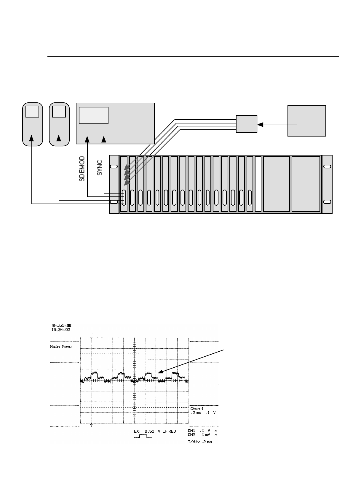
If you have the table-top test kit (BPM-KIT), use the following set-up:
Oscilloscope
Ch.1 Ext. trig.
SDEMOD SYNC
Beam
Position
Monitor
RF Source
AC mains
A
B
C
D
Power
splitter
8-bit DIP switch
Σ
X
Y
agc
clock
DVM DVM
Power
supply
YX
Place all DIP switches to the left: OFF
BERGOZ Instrumentation
Multiplexed
01630 Saint Genis Pouilly, France
Beam Position Monitor
Tel. +33-450.426.642
Fax +33-450.426.643
Page 3 User’s manual
BERGOZ Instrumentation - 01630 Saint Genis Pouilly, France - Tel.: +33-450.426.642 - Fax: +33-450.426.643
email: [email protected] - http://www.bergoz.com - Registre des Métiers: Bourg-en-Bresse - Registre des ingénieurs: Zurich
TVA-VAT-IVA-USt. Nº FR88414997130 - Sàrl. capital 152K
- Siren 414 997 130 R.C.S. Bourg - APE 332B
QUICK CHECK (Cont'd)
If you have a 19” chassis (BPM-RFC/X), use the following set-up:
DVM DVM
YX
RF Source
Power
splitter
Oscilloscope
Ch.1 Ext. trig.
To button inputs
(back of chassis)
Attach the equipment together as shown above.
Set the oscilloscope time base on 0.2 ms / div.
Ext. trigger connects to SYNC signal, trigger level 0.2V, 1 M
Ω
AC coupling
Channel 1 to SDEMOD signal, sensitivity 0.1 V / div., 1 M
Ω
AC coupling
Set the RF source to the operating frequency.
Amplitude ca. -13 dBm
Note:
The BPM module operating frequency is written on the F–Key daughter board.
To access the F–Key, remove the BPM module shield.
Set the X and Y voltmeters range in such a way that millivolts are readable.
Connect to AC mains, the oscilloscope should display:
Synchronous demodulated signal.
Each period 100…125µs represents
the successive buttons A, B, C, D, A, B…
The signals are equalized before delivery
of the BPM module, using a precision
input 4-way splitter.
Differences in signal level as shown here
are due to uneven input signals.
Note: 1 dB input signal difference gives
ca. 300 mV of demodulated signal
amplitude difference
BERGOZ Instrumentation
Multiplexed
01630 Saint Genis Pouilly, France
Beam Position Monitor
Tel. +33-450.426.642
Fax +33-450.426.643
Page 4 User’s manual
BERGOZ Instrumentation - 01630 Saint Genis Pouilly, France - Tel.: +33-450.426.642 - Fax: +33-450.426.643
email: [email protected] - http://www.bergoz.com - Registre des Métiers: Bourg-en-Bresse - Registre des ingénieurs: Zurich
TVA-VAT-IVA-USt. Nº FR88414997130 - Sàrl. capital 152K
- Siren 414 997 130 R.C.S. Bourg - APE 332B

QUICK CHECK (Cont'd)
It may be that the demodulated button signals are uneven, like this:
Synchronous demodulated signal.
Each period 100…125µs represents
the successive buttons A, B, C, D, A, B…
This demodulated signal indicates large
difference of power applied to the button
inputs.
Differences in signal level as shown here
exceed 1 dB.
The on-board button attenuators could be adjusted to compensate for the input power difference,
therefore equalize the signals, but...
Do not readjust the on-board attenuators before you are familiar with the BPM behaviour.
What if the display does not look as shown
Check that all DIP switches of the table-top test kit are set OFF (left position).
Check that all cables are properly connected.
Check that the RF source gives the required frequency and amplitude.
If you have more than one BPM module, try another one.
Getting familiar with the BPM
Vary the power from the RF source to simulate beam intensity variations.
Explore the range from 0 dBm down to -90 dBm.
Remember that the 4-way power splitter absorbs some power: adjust for it !
While the RF source output power is changed, observe the intensity dependence of X and Y
outputs on the voltmeters. If the BPM electronics gain has been set for 1 V/mm, each mV is
equivalent to 1 µm beam displacement.
Measure the rms noise at various signal levels.
Observe the noise spectrum with an FFT or baseband spectrum analyser, at various signal levels.
BERGOZ Instrumentation
Multiplexed
01630 Saint Genis Pouilly, France
Beam Position Monitor
Tel. +33-450.426.642
Fax +33-450.426.643
Page 5 User’s manual
BERGOZ Instrumentation - 01630 Saint Genis Pouilly, France - Tel.: +33-450.426.642 - Fax: +33-450.426.643
email: [email protected] - http://www.bergoz.com - Registre des Métiers: Bourg-en-Bresse - Registre des ingénieurs: Zurich
TVA-VAT-IVA-USt. Nº FR88414997130 - Sàrl. capital 152K
- Siren 414 997 130 R.C.S. Bourg - APE 332B

ON-BOARD ATTENUATORS ADJUSTMENT
Introduction
The BPM module is equipped with four on-board adjustable attenuators. Each attenuator
adjustment range exceeds 1 dB. We recommend that all BPM modules are adjusted on center for
equal power applied to the four button inputs. The on-center condition is satisfied when the
amplitude variation of SDEMOD is below 20mV at –10 dBm input power. Then, X
≈0 and Y≈0.
The remaining X and Y zero offsets can be eliminated (within ±20mV) by fine tuning the
attenuators.
The BPM electronics has best performance, i.e. more linearity over the dynamic range, when the
power difference between input signals is kept to a minimum. This is obtained for a centered beam
and cables with equal attenuation.
The on-board attenuators can be used –within their limited 1-dB range– to compensate for an off-
centered beam or unequal cable attenuations.
Procedure
The table-top test kit (BPM-KIT) is the easiest setup to adjust the attenuators.
Extract the BPM module and proceed as described in “Quick Check”.
Note: BPM modules can be removed and inserted while the power is on.
The card extender (BPM-XTD) allows a BPM module to be extended out of its chassis slot.
Extract the BPM module, install the extender and proceed as in “Quick Check”.
Note: The card extender has unequal button-to-button attenuations. It introduces an offset in
X and Y. The card extender offset was measured at the time of shipment. To recheck it, measure
the X and Y offsets with and without extender.
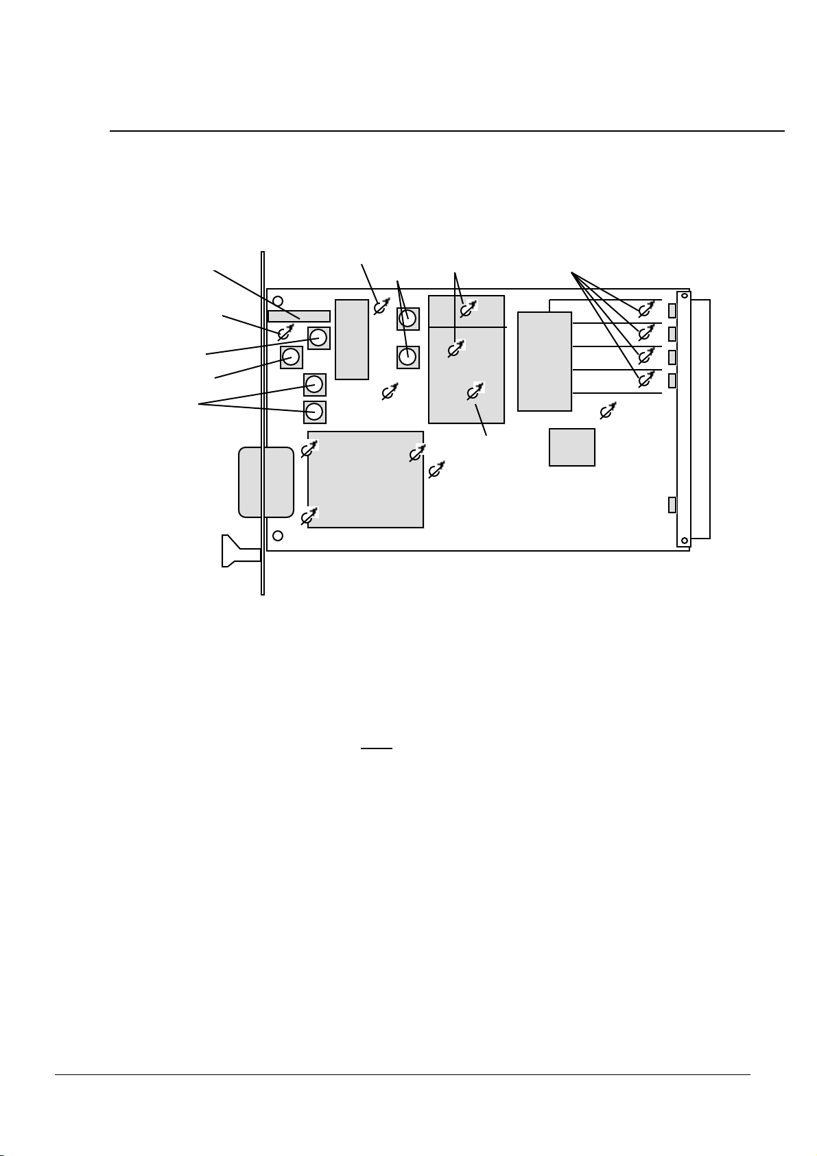
To adjust the on-board attenuators, we recommend that the shield is removed:
To remove shield: Remove screws (2) from under
On-board attenuators access
holes
BERGOZ Instrumentation
Multiplexed
01630 Saint Genis Pouilly, France
Beam Position Monitor
Tel. +33-450.426.642
Fax +33-450.426.643
Page 6 User’s manual
BERGOZ Instrumentation - 01630 Saint Genis Pouilly, France - Tel.: +33-450.426.642 - Fax: +33-450.426.643
email: [email protected] - http://www.bergoz.com - Registre des Métiers: Bourg-en-Bresse - Registre des ingénieurs: Zurich
TVA-VAT-IVA-USt. Nº FR88414997130 - Sàrl. capital 152K
- Siren 414 997 130 R.C.S. Bourg - APE 332B
ON-BOARD ATTENUATORS ADJUSTMENT (Cont’d)
Beam Position Monitor board
BUTA
BUTB
BUTC
BUTD
IF BPF
Level shift
AGC
IF BPF
RF BPF
Attenuators
Clock
adjust
Y gain
Σadj.
X gain
LO
Lock
Carrier phase
F-Key
Demod. phase
Demodulator
SBS-mode
fixed
level gain
GaAs
switch
driver
GATE
(option)
Single
Button
Sampling
(option)
Mixer
LNA
IF
IC
To adjust the attenuators, use a screwdriver with a ceramic tip. A metal tip changes the signal !
Set all four on-board adjustable attenuators 1/4 of a turn clockwise. One turn is ca. 3
π/2.
Set the RF source to the BPM operating frequency. Set power level such that -10 dBm is applied to
each button, taking the 4-way power splitter attenuation into account.
Adjust progressively A, B, C and D attenuators until the SDEMOD signal has minimum level
differences.
Note: The BPM module adjustment
must
be done by observing SDEMOD to minimize the button-
to-button power differences. It can not be done by simply adjusting X=0 and Y=0 : There is an
infinite number of A,B,C,D combinations satisfying X=0 and Y=0; i.e. A=1, B=2, C=1, D=2
yields X=A-B-C+D=0 and Y=A+B-C-D=0.
BUTTON SAMPLING
The BPM module has an on-board clock to drive the input multiplexer. The internal clock
frequency is adjustable by the “Clock adjust” potentiometer from 8 to 10 kHz.
Each button is thus sampled during 100 to 125 µs, and a complete scan is made in 400 to 500 µs.
The beginning of each scanning cycle is available as output signal SYNC rising edge (See
“Connector Pins Allocation”, this manual). SYNC frequency is 1/4 of sampling frequency.
The internal clock can be overridden by an external clock.
BERGOZ Instrumentation
Multiplexed
01630 Saint Genis Pouilly, France
Beam Position Monitor
Tel. +33-450.426.642
Fax +33-450.426.643
Page 7 User’s manual
BERGOZ Instrumentation - 01630 Saint Genis Pouilly, France - Tel.: +33-450.426.642 - Fax: +33-450.426.643
email: [email protected] - http://www.bergoz.com - Registre des Métiers: Bourg-en-Bresse - Registre des ingénieurs: Zurich
TVA-VAT-IVA-USt. Nº FR88414997130 - Sàrl. capital 152K
- Siren 414 997 130 R.C.S. Bourg - APE 332B
EXTERNAL CLOCK
An external clock can be applied to the BPM module to drive the input multiplexer.
It must be applied to CLK* (See “Connector Pins Allocation”, this manual).
Amplitude
≥6Vp-p, or ≥
3 V positive-going, pulse length
≥
10µs.
It overrides the internal clock after a few milliseconds.
The BPM module operates properly up to an external frequency of 40 kHz, therefore the sampling
of each button input can be made in 25µs, the four buttons can be sampled in 100µs. As a result,
the beam position can be effectively sampled up to a frequency of 10 kHz.
The use of an external clock –and faster beam position sampling– may be required to eliminate
aliasing of certain beam motions.
The performance of the BPM module is not affected by a higher sampling frequency:
• The X/Y output noise increase is not noticeable
• The X/Y zero (on-center) dc values are slightly shifted, but stable at each particular frequency.
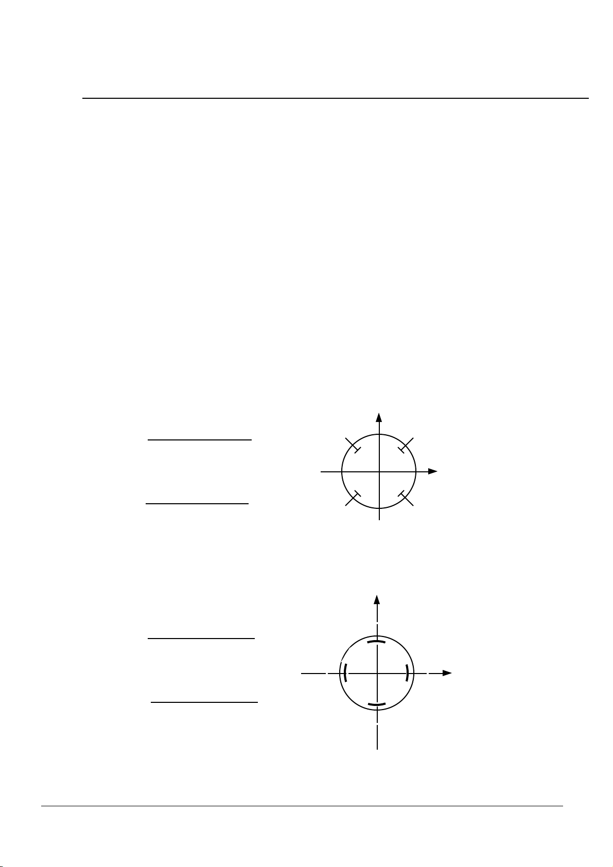
ALGORITHM &
POLARITY CONVENTION
45° buttons
VA+ VB+ VC +VD
VA+ VB- VC - VD
Ky
X=VA- VB- VC + VD
VA+ VB+ VC +VD
Kx
Y=
Y
X
AB
C D
Orthogonal buttons
B
C
D
AX
Y
KyY =VA+ VB+ VC +VD
VB- VD
X=VA- VC
VA+ VB+ VC +VD
Kx
BERGOZ Instrumentation
Multiplexed
01630 Saint Genis Pouilly, France
Beam Position Monitor
Tel. +33-450.426.642
Fax +33-450.426.643
Page 8 User’s manual
BERGOZ Instrumentation - 01630 Saint Genis Pouilly, France - Tel.: +33-450.426.642 - Fax: +33-450.426.643
email: [email protected] - http://www.bergoz.com - Registre des Métiers: Bourg-en-Bresse - Registre des ingénieurs: Zurich
TVA-VAT-IVA-USt. Nº FR88414997130 - Sàrl. capital 152K
- Siren 414 997 130 R.C.S. Bourg - APE 332B

PRINCIPLE OF OPERATION
The signal from the BPM buttons are time-multiplexed into a single signal applied to a
superheterodyne receiver. The demodulated signal is demultiplexed into four button value stored in
analog memories. The four signals are summed and the sum is maintained constant by an
automatic gain control. The sum of all buttons being equal, the beam position is obtained by the
analog summations X=A–B–C+D and Y=A+B–C–D for 45° buttons, and Y=D–B and Y=A–C for
orthogonal buttons.
More details in the attached Annexes:
Annex II.
Precision Analog Signal Processing for Beam Position Measurements in Electron
Storage Rings, J.A. Hinkson and K.B. Unser, Proceedings of the 2nd DIPAC,
Travemünde 1995
Annex III.
New Generation Electronics Applied to Beam Position Monitors, Klaus B. Unser
1996 Beam Instrumentation Workshop, Argonne National Laboratory.
Many of the fundamental principles of our BPM module were developed by John W. Bittner and
Richard W. Biscardi for the National Synchrotron Light Source at Brookhaven National
Laboratory. U.S. Patent 5,001,416 was granted to them on March 19, 1991.
BLOCK DIAGRAM
frequency
synthesizer
filter
BPF LNA
sample/hold
S/H
S/H
S/H
S/H
attenuators
LO
oscillator
phase detector
mixer
21.4 MHz
filter
BPF
amplifier
IF
filter
BPF
VCO
LPF
limiter
phase detector
LPF
LPF
LPF
LPF
1-dB adj.
A
B
C
D
X
Y
Σ
AGC peak/hold
single
button sampling P/H
F-
key
plug-in
A
B
C
DDRV
switch
driver
MUX
CLK
ext. clock
button address, fast gate
reset
filter
amplifier
GaAs
switches
automatic gain
control
AL
BERGOZ Instrumentation
Multiplexed
01630 Saint Genis Pouilly, France
Beam Position Monitor
Tel. +33-450.426.642
Fax +33-450.426.643
Page 9 User’s manual
BERGOZ Instrumentation - 01630 Saint Genis Pouilly, France - Tel.: +33-450.426.642 - Fax: +33-450.426.643
email: [email protected] - http://www.bergoz.com - Registre des Métiers: Bourg-en-Bresse - Registre des ingénieurs: Zurich
TVA-VAT-IVA-USt. Nº FR88414997130 - Sàrl. capital 152K
- Siren 414 997 130 R.C.S. Bourg - APE 332B

PERFORMANCE
BPM electronics for closed orbit measurement are characterised by:
•
Sampling frequency of the button signals
•
Output signal noise (resolution) vs. input signal strength
•
Dynamic range of signals that may be applied to the unit, itself characterized by:
•
Position error (linearity) vs. input signal strength for equal signals (on-center beam)
•
Position error (linearity) vs. input signal strength for unequal signals (off-center beam)
•
Drifts caused by environmental changes
The performance of the first regular production units is given hereafter:
Sampling frequency
Up to 40 kHz. X and Y are updated at the rate up to 10 kHz. With the internal (default) clock, the
sampling frequency is 2…2.5 kHz.
Output signal noise (resolution) vs. input signal strength
–90 dBm
–80 dBm
–70 dBm
–60 dBm
–50 dBm
100 mVrms /√Hz
10 mVrms /
√Hz
1 mVrms /
√Hz
100 µVrms /√Hz
10 µVrms /√Hz
Signal power applied to BPM inputs
Noise in ±10V Y output at 1 V/mm sensitivity for 17.12 -mm chamber in Y
Unit tested: BPM499.658MHz-X0.0607V/%-Y0.1712V/% serial #0035
Test instrument: Stanford Research SR760, Average rms = 50
Noise spectra at higher input power are
similar to the spectrum at –50 dBm input
BERGOZ Instrumentation
Multiplexed
01630 Saint Genis Pouilly, France
Beam Position Monitor
Tel. +33-450.426.642
Fax +33-450.426.643
Page 10 User’s manual
BERGOZ Instrumentation - 01630 Saint Genis Pouilly, France - Tel.: +33-450.426.642 - Fax: +33-450.426.643
email: [email protected] - http://www.bergoz.com - Registre des Métiers: Bourg-en-Bresse - Registre des ingénieurs: Zurich
TVA-VAT-IVA-USt. Nº FR88414997130 - Sàrl. capital 152K
- Siren 414 997 130 R.C.S. Bourg - APE 332B
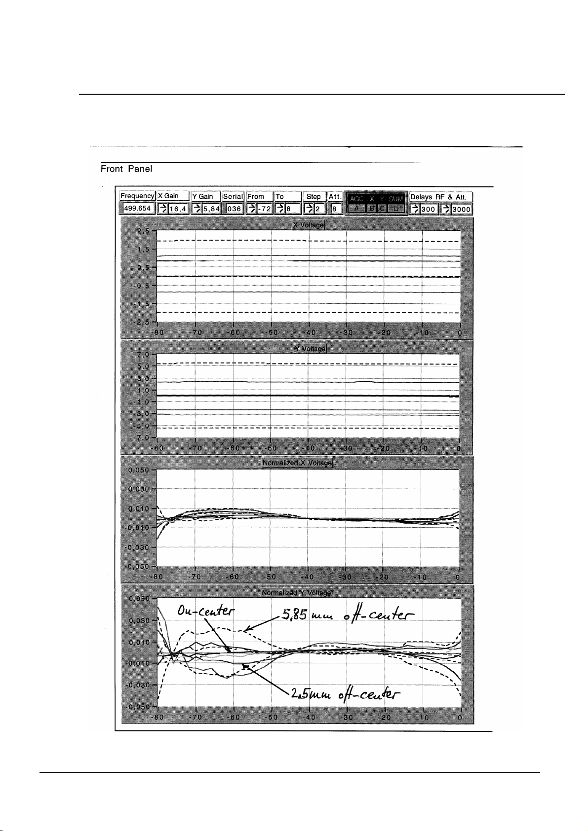
PERFORMANCE (Cont’d)
Position error (linearity) vs. input signal strength
LabVIEW data acquisition virtual instrument using NB-MIO-16XH sampler, by Karen Scott
BERGOZ Instrumentation
Multiplexed
01630 Saint Genis Pouilly, France
Beam Position Monitor
Tel. +33-450.426.642
Fax +33-450.426.643
Page 11 User’s manual
BERGOZ Instrumentation - 01630 Saint Genis Pouilly, France - Tel.: +33-450.426.642 - Fax: +33-450.426.643
email: [email protected] - http://www.bergoz.com - Registre des Métiers: Bourg-en-Bresse - Registre des ingénieurs: Zurich
TVA-VAT-IVA-USt. Nº FR88414997130 - Sàrl. capital 152K
- Siren 414 997 130 R.C.S. Bourg - APE 332B
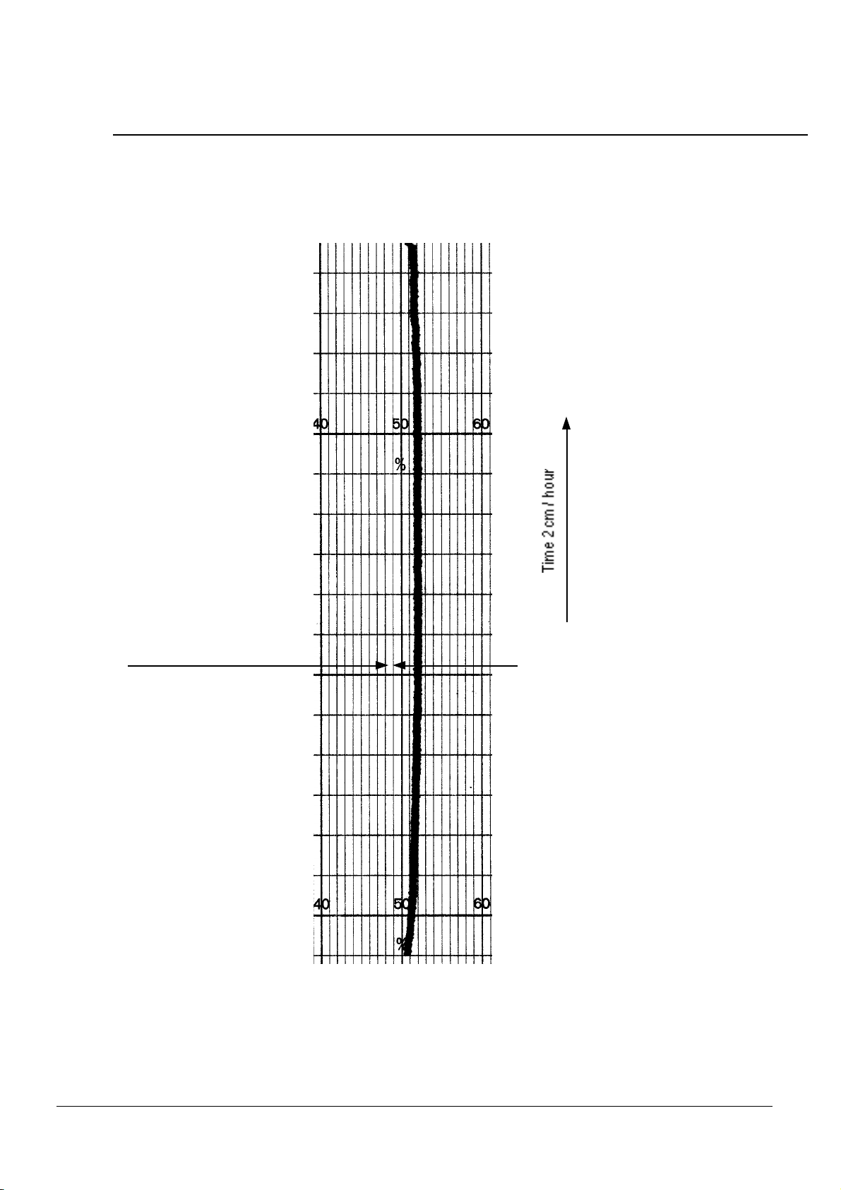
PERFORMANCE (Cont’d)
Temperature dift
Unit tested:
LNLS Campinas, serial #020
BPM-476.003MHz-X0.21V/%-Y0.21V/%
Date: Apr. 29, 1996, by Alain Charvet
DRIFT of the X output
Cold start
9 hours recording
Day/Night temperatures
Min. = 19.4°C
Max. = 25.3°C
1 mV / div.
BERGOZ Instrumentation
Multiplexed
01630 Saint Genis Pouilly, France
Beam Position Monitor
Tel. +33-450.426.642
Fax +33-450.426.643
Page 12 User’s manual
BERGOZ Instrumentation - 01630 Saint Genis Pouilly, France - Tel.: +33-450.426.642 - Fax: +33-450.426.643
email: [email protected] - http://www.bergoz.com - Registre des Métiers: Bourg-en-Bresse - Registre des ingénieurs: Zurich
TVA-VAT-IVA-USt. Nº FR88414997130 - Sàrl. capital 152K
- Siren 414 997 130 R.C.S. Bourg - APE 332B

CLOSED ORBIT OPERATING MODE
This is the most simple operating mode. It is the default mode, i.e. when no external control
signals are applied to the BPM module.
In the default mode, the internal clock controls the button sampling frequency (8…10 kHz).
The average beam position is available as:
XOUT
X output. Analog output. (See Algorithm & Polarity Conventions, this manual)
Voltage range: –10V…+10V. Zero is centered beam.
YOUT
Y output. Analog output. (See Algorithm & Polarity Conventions, this manual)
Voltage range: –10V…+10V. Zero is centered beam.
The value of each individual button A, B, C and D is also available. They can be used to compute
–externally– the beam position with algorithms other than
∆/Σ:
AOUT
A output. Analog output.
Voltage range: 0…+10V. Pedestal ca. 1 V.
BOUT
A output. Analog output.
Voltage range: 0…+10V. Pedestal ca. 1 V.
COUT
A output. Analog output.
Voltage range: 0…+10V. Pedestal ca. 1 V.
DOUT
A output. Analog output.
Voltage range: 0…+10V. Pedestal ca. 1 V.
In closed orbit mode, the BPM module performance can be monitored with:
PLLOCK
PLL demodulator in lock & good signal level. TTL output.
High = PLL in lock and signal level OK
Low = PLL out of lock or signal level poor
The DB9 female front-panel connector allows the observation of the multiplexed demodulated
signal:
SDEMOD
Synchronous demodulator output. Analog output. For oscilloscope viewing.
SYNC
Synchronization pulse. TTL output. Positive-going. For oscilloscope trigger.
BERGOZ Instrumentation
Multiplexed
01630 Saint Genis Pouilly, France
Beam Position Monitor
Tel. +33-450.426.642
Fax +33-450.426.643
Page 13 User’s manual
BERGOZ Instrumentation - 01630 Saint Genis Pouilly, France - Tel.: +33-450.426.642 - Fax: +33-450.426.643
email: [email protected] - http://www.bergoz.com - Registre des Métiers: Bourg-en-Bresse - Registre des ingénieurs: Zurich
TVA-VAT-IVA-USt. Nº FR88414997130 - Sàrl. capital 152K
- Siren 414 997 130 R.C.S. Bourg - APE 332B

FIRST TURN CAPABILITY
When the Single Button Sampling option (BPM-SBS) is installed on the BPM module board, the
BPM module has a limited capability of monitoring the first turn(s) after beam injection.
The BPM-SBS option consists of a small piggy-back plug-in board which installs on the BPM
main board.
The first turn capability offered when BPM-SBS is installed consists of measuring four successive
injections, first with button A, second with button B, third with button C and fourth with button D.
The value of each button is given by the BPM module on the X analog output XOUT. It
corresponds to the highest signal received by the selected button, until it is reset by the user. A
peak and hold (P/H) circuit on the BPM-SBS piggy-back board implements it.
The value of each button must be measured and the position must be calculated by an external
computer.
When the SBS mode is enabled, the Automatic Gain Control (AGC) is disabled. The amplifiers
gain is controlled by a 20-turn potentiometer “Gain Adjust” located on the BPM module front panel.
The potentiometer must be roughly adjusted so that the amplifiers gain is sufficient in relation to the
injected charge and the pickups sensitivity. Note: The gain may be different among BPM modules.
The Single Button Sampling mode is enabled by pulling down:
SBS*
Single Button Sampling mode. TTL input.
The button is designated by a 2-bit address:
BADD0*
Button addresses. TTL input. Active only when SBS mode is enabled.
BADD1*
BADD1 BADD0
Button A
high low
Button B low low
Button C high high
Button D
low high
Default value: Button C
The output is obtained on:
XOUT
Analog output value of button addressed, from P/H circuit
Voltage range: 0…+5V, pedestal
≈
0.5V.
Settling time < 1 ms
Signal droop negligible up to 100 ms.
The Peak and Hold circuit is reset by pulling down:
PHRESET*
Peak and Hold Reset. TTL input.
This input has no internal pull-up.
Pull up to reset (min 5 ms).
Pull down to measure bunch, at least 1 ms before bunch. Keep down to hold.
But don’t pull down too early, or SBS will measure peak ambiant noise !
BERGOZ Instrumentation
Multiplexed
01630 Saint Genis Pouilly, France
Beam Position Monitor
Tel. +33-450.426.642
Fax +33-450.426.643
Page 14 User’s manual
BERGOZ Instrumentation - 01630 Saint Genis Pouilly, France - Tel.: +33-450.426.642 - Fax: +33-450.426.643
email: [email protected] - http://www.bergoz.com - Registre des Métiers: Bourg-en-Bresse - Registre des ingénieurs: Zurich
TVA-VAT-IVA-USt. Nº FR88414997130 - Sàrl. capital 152K
- Siren 414 997 130 R.C.S. Bourg - APE 332B

FIRST TURN CAPABILITY (Cont’d)
Timing
≥10 ms
≥1 ms
Beam
PHRESET*
Button signal
XOUT
≤1 ms
Gain setting
In Single Button Sampling mode (SBS* pulled down), the automatic gain control (AGC) is
disabled. The circuit gain is set by the front panel potentiometer labelled “Gain Adjust”.
The potentiometer must be set so that the injected bunch causes the X output XOUT to be ca.
+2.5V. In practice, if the beam is not on center, it might be necessary to read successively all four
buttons and set the 4-buttons average output value to ca. +2.5 V.
After setting the gain potentiometer, the setting can be recorded, in order to reset it to the same value
whenever needed: While the BPM is in Single Button Sampling mode, measure the AGC voltage
and record it. The AGC voltage is a reliable indication of the potentiometer gain setting.
The AGC voltage (VAGC) is available from the front panel DB9 connector (pin 3) and from the
DIN41612 rear connector (pin c19). On the BPM chassis ref. BPM-RFC/xx, it is available from
the DB15 connector (pin 2).
BERGOZ Instrumentation
Multiplexed
01630 Saint Genis Pouilly, France
Beam Position Monitor
Tel. +33-450.426.642
Fax +33-450.426.643
Page 15 User’s manual
BERGOZ Instrumentation - 01630 Saint Genis Pouilly, France - Tel.: +33-450.426.642 - Fax: +33-450.426.643
email: [email protected] - http://www.bergoz.com - Registre des Métiers: Bourg-en-Bresse - Registre des ingénieurs: Zurich
TVA-VAT-IVA-USt. Nº FR88414997130 - Sàrl. capital 152K
- Siren 414 997 130 R.C.S. Bourg - APE 332B
FIRST TURN CAPABILITY (Cont’d)
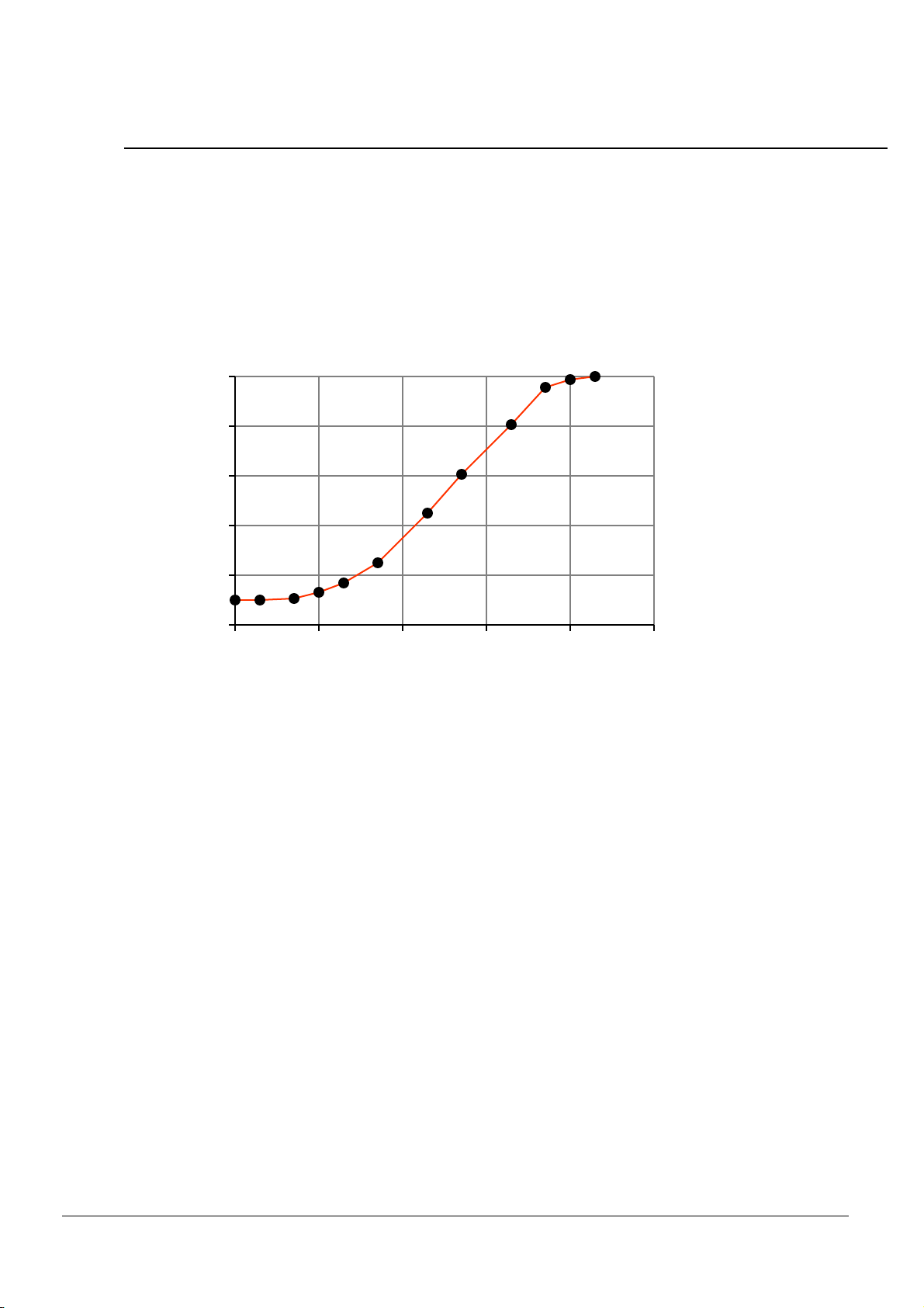
Button value readout
The output signal XOUT is (in first approximation) proportional to the logarithm –or dB value– of
the button signal strength. The signal has a pedestal
≈
0.5V, it has the same value for all four
buttons.
5.00
4.00
3.00
2.00
1.00
0.00
X
O
U
T
5040302010
0
Relative button signal strength [dB]
The pedestal must be read in the absence of beam and deducted from the button value reading.
The phase relationship between the beam bunch and the superheterodyne receiver local oscillator
(LO) is arbitrary. As a consequence, the down-converted signal varies in amplitude, depending on
the phase angle. Amplitude variations from bunch to bunch (i.e. from conversion to conversion)
can be as high as 20%. These variations are purely statistical and can be eliminated by averaging a
series of readings.
BERGOZ Instrumentation
Multiplexed
01630 Saint Genis Pouilly, France
Beam Position Monitor
Tel. +33-450.426.642
Fax +33-450.426.643
Page 16 User’s manual
BERGOZ Instrumentation - 01630 Saint Genis Pouilly, France - Tel.: +33-450.426.642 - Fax: +33-450.426.643
email: [email protected] - http://www.bergoz.com - Registre des Métiers: Bourg-en-Bresse - Registre des ingénieurs: Zurich
TVA-VAT-IVA-USt. Nº FR88414997130 - Sàrl. capital 152K
- Siren 414 997 130 R.C.S. Bourg - APE 332B

SINGLE BUNCH / SINGLE BEAM MODE
The Fast Gate option (BPM-FG) allows to monitor the position of a single bunch out of a beam, or
to separate beams in colliders, provided the selected bunch can be fitted in the gate of 20 ns
minimum width. The BPM-FG option consists of a modified GaAs switch driver –with a NIM
pulse command– replacing the standard switch driver, and the addition of the GATE input
connector.
The Fast Gate may be used with the Closed Orbit mode and with the Single Button Sampling mode.
•
In Closed Orbit mode, the Fast Gate allows to monitor the average position of a single bunch, or
selected bunches.
•
In First Turn mode, the Fast Gate allows to capture the first turn only, or any other subsequent
turn.
The gate is defined by:
GATE
External fast NIM gate. Only with option BPM-FG.
Gate width≥
20 ns.
The Fast Gate feature works like this:
•
When no signal is applied to GATE (disconnected), the Fast Gate feature is not active.
•
When GATE is pulled down by a NIM (-20 mA) signal, all multiplexer GaAs switches
remain open (non-conducting).
•
When GATE is released high (0 mA), the GaAs switch addressed by the button address lines
BADD0 and BADD1 closes (conducting).
Fast Gate timing
≥20 ns
Beam
GATE
0
GaAs switch
non-conducting non-conducting
conducting
Gated bunches
To display the above signals in their correct time relation, the service module BPM-SERV/RF can
be inserted in place of a BPM module. It provides the RF signals BUTA, BUTB, BUTC, BUTD
and the delayed GATE signal.
BERGOZ Instrumentation
Multiplexed
01630 Saint Genis Pouilly, France
Beam Position Monitor
Tel. +33-450.426.642
Fax +33-450.426.643
Page 17 User’s manual
BERGOZ Instrumentation - 01630 Saint Genis Pouilly, France - Tel.: +33-450.426.642 - Fax: +33-450.426.643
email: [email protected] - http://www.bergoz.com - Registre des Métiers: Bourg-en-Bresse - Registre des ingénieurs: Zurich
TVA-VAT-IVA-USt. Nº FR88414997130 - Sàrl. capital 152K
- Siren 414 997 130 R.C.S. Bourg - APE 332B

X AND Y GAIN ADJUSTMENT
Conventions
BPM modules are referenced in terms of operating frequency and X / Y gains as they appear on the
order code:
BPM- . MHz-X . V/%-Y . V/%
Operating frequency
Horizontal gain
Vertical gain
The BPM module X / Y gain units are V/%.
The BPM buttons sensitivity is -depending on the laboratory- expressed as:
•
Vacuum chamber calibration factor [mm]
•
Vacuum chamber Sensitivity [mm
-1
] or [%/mm] or [dB/mm]
The overall gain of the BPM buttons and electronics system is expressed in V/mm.
It is the product:
Gain [V/mm] = Vacuum chamber Sensitivity [%/mm] x BPM module gain [V/%].
BPM module gain adjustment
The X and Y gains have been adjusted before shipment according to the order code.
Two on-board potentiometers allow a fine adjustment of the gain: X gain and Y gain:
BUTA
BUTB
BUTC
BUTD
IF BPF
Level shift
AGC
IF BPF
RF BPF
Attenuators
Clock
adjust
Y gain
Σadj.
X gain
LO
Lock
Carrier phase
F-Key
Demod. phase
Demodulator
SBS-mode
fixed
level gain
GaAs
switch
driver
GATE
(option)
Single
Button
Sampling
(option)
Mixer
LNA
IF
IC
The gain potentiometers are accessible via holes bored through the Single Button Sampling (option)
piggy-back board.
BERGOZ Instrumentation
Multiplexed
01630 Saint Genis Pouilly, France
Beam Position Monitor
Tel. +33-450.426.642
Fax +33-450.426.643
Page 18 User’s manual
BERGOZ Instrumentation - 01630 Saint Genis Pouilly, France - Tel.: +33-450.426.642 - Fax: +33-450.426.643
email: [email protected] - http://www.bergoz.com - Registre des Métiers: Bourg-en-Bresse - Registre des ingénieurs: Zurich
TVA-VAT-IVA-USt. Nº FR88414997130 - Sàrl. capital 152K
- Siren 414 997 130 R.C.S. Bourg - APE 332B
Table of contents
Popular Valve Positioner manuals by other brands


GE
GE BAKER HUGHES Masoneilan SVi 1000 quick start guide

OMC
OMC RE20 Installation, operation and maintenance manual

Montana Instruments
Montana Instruments The Rook CryoAdvance 50 user manual

SMAR
SMAR FY301 Instruction, operations & maintenance manual

Vector
Vector MZ3-FA-V11 manual

Micronix
Micronix PPS-20 Series Reference manual


