manuals.online logo
Brands
  1. Home
  2. •
  3. Brands
  4. •
  5. Vector
  6. •
  7. Valve Positioner
  8. •
  9. Vector MZ3-FA-V11 User manual

Vector MZ3-FA-V11 User manual

MZ3-FA-V11
Doc: 70-00-0836 V2.2, 20210628 © Vector Controls GmbH, Switzerland Page 1
Subject to alterations www.vectorcontrols.com
MZ3-FA-V11
Controller/positioner for comfort ventilation
Functions
•Positioner and controller for comfort ventilation with touch panel
•Manual operation with up to 4 Levels, OFF, minimum air, 1st Level, 2nd
Level, maximum air
•AUTO operation: The controller activates the ventilation based on controls
curve. The controls curve may be adjusted
•Automatic reset of the maximum air level
•One 0…10 VDC controls output to control the ventilation system
•One 0…10 VDC input for connection of a CO2 or other sensors
•Password protected controls settings
•New with V2.0: Copy of settings with accessory
Applications
This device is designed to control ventilation systems for comfort applications.
For example, for well insulated residential areas which are required to be ventilated.
General description
The MZ3-FA-V11 is a microprocessor-controlled precision positioner and controller with touch panel. Through user and
engineering parameters the positioner may be configured to work for most of the standard ventilation applications. The
device is pre-configured according to this documentation. Settings such as switching levels of the control curve and
ventilation strengths for each Level may be adjusted. The configuration may be performed using the programming device
called OPA-S. This device may be used as well to visualize measuring values.
Ordering
Item
Item code
Variant
Features
MZ3-FA-V11-B-T4-W
40-100229
Blue LED
White frame,
Inidcation:
Minimum, Normal, Maximum, Party
Compact positioner/controller
in a white frame, with one
0-10 VDC input and output.
Operation as 4-Level switch
with touch panel and AUTO
function.
OPA-S
40-500006
Programming and display device
LCD display for surface
mounting or handheld
operation.
AEC-PM2
40-500130
Memory-Device. Used for copying
settings
Stores settings of MZ3
Interface to the ventilation system
The positioner works with all ventilation systems that are designed with a 0...10 VDC or 2...10 VDC input signal.
Selection of transmitters
The positioner works with all sensors that provide an output signal of 0...10 VDC or 2...10 VDC. The measuring range
needs to be observed.
For example: CO2 0...2000 ppm = 0...10 VDC or 2...10 VDC.
Party
Maximum
Normal
Minimum
MZ3-FA-V11
Doc: 70-00-0836 V2.2, 20210628 © Vector Controls GmbH, Switzerland Page 2
Subject to alterations www.vectorcontrols.com
Technical data
Power supply
Operating voltage
24 V AC/DC ± 10%, 50/60 Hz, Class 2 48 VA max
Power consumption
Max. 1,0 VA
Power backup for real time clock
Super cap, keeps clock running for 24 h without
power
Electrical connection
Terminal connectors,
wire 0,34-2,5 mm2(AWG 22…13)
Signal inputs
Analog input
0..10 VDC
Signal outputs
Analog outputs
Output signal
Resolution
Maximum load
DC 0...10 VDC
9.76 mV (10 Bit)
2 mA or 5 kΩ
Environment
Operation
Climatic conditions
Temperature
Humidity
To IEC 721-3-3
class 3K5
0...50 ° C (32...122 ° F)
< 95% RH non-condensing
Transport & storage
Climatic conditions
Temperature
Humidity
Mechanical conditions
To IEC 721-3-2 and IEC 721-3-1
class 3K3 and class 1K3
-25…70 °C (-13…158 °F)
< 95% RH non-condensing
class 2MT2
Standards
Degree of protection
Wall mounted: IP40 acc. EN 60529
Not installed: IP00 acc. EN 60529
Safety class
III (IEC 60536)
General
Housing material:
Fireproof ABS+PC plastic (UL94 class V-0)
Dimensions (H x W x D)
including packaging
120 x 120 x 70 mm (4,7” x 4,7” x 2,8”)
Weight (incl. packaging)
150 g (5.3 oz)
Product testing and certification
Declaration of
Conformity
Information on the conformity of our products can be found on our website
www.vectorcontrols.com on the corresponding product page under "Downloads".
Dimensions mm (in)
The MZ3-FA-V11 is so designed that it can be incorporated into a commercially available flush box (Feller EDIZIOdue®
frame and mounting plate are included).
MZ3-FA-V11
Doc: 70-00-0836 V2.2, 20210628 © Vector Controls GmbH, Switzerland Page 3
Subject to alterations www.vectorcontrols.com
Connection diagram
Description:
1 Power supply: 24 VAC, +24 VDC
2 Power supply: 0 V, -24 VDC, internally connected to signal common
3 Analog input for sensor 0…10 VDC
4 Analog output ventilation: 0…10 VDC
Installation and safety advice
This device is intended to be used as positioner for comfort ventilation systems. Where a device failure endangers human
life and/or property, it is the responsibility of the client to add additional safety devices to prevent or detect a system
failure caused by such a device failure.
The device contains electronic components and must not be disposed of with household waste.
Setting of the device to keep fan running in minimal volume in OFF mode
If JP1 in position 1-2, the output is off in OFF mode. Ventilation switches off.
If JP1 in position 2-3 or removed, the output stays in OFF mode in Level 0 (minimum air volume)
View back part when front plate removed
New with V2.0: Parameter copy
It is now possible to copy settings to an accessory (AEC-PM2) and to copy them back to other MZ3. For this, remove the
front panel of the MZ3, insert AEC-PM2 in the designated plug. Connect OPA-S and copy parameter from MZ3 to AEC-PM2
by setting OP06 to 1.
AEC-PM2 “Data” LED is ON for 5 seconds after successful parameter copy and OP06 is set to 0. If the parameter copy
failed the LED blinks for 5 seconds and OP06 is set to 7.
Copy parameter from AEC-PM2 to MZ3 simply by pressing the “Copy” button on the AEC-PM2. AEC-PM2 “Data” LED is ON
for 5 seconds after successful parameter copy. If the parameter copy failed the LED blinks for 5 seconds.
MZ3-FA-V11
Doc: 70-00-0836 V2.2, 20210628 © Vector Controls GmbH, Switzerland Page 4
Subject to alterations www.vectorcontrols.com
Display & Operation
ON/OFF operation
The device is activated by pressing the ON/OFF button.
Depending on the position of JP1, the minimum air volume
remains active even during OFF mode. In OFF mode, the
operating mode symbol lights up with reduced intensity
Manual operation
The following operation modes will be activated through
repeated pressing of the Level button:
Level 0 = Minimum air volume
Level 1
Level 2
Level 3 = Maximum air volume
Auto operation
The operating modes are activated after 2 seconds. This prevents unnecessary switching when setting the device. The
Level-indication and buttons light up in green or blue depending on the type of device.
The device is equipped with proximity detection. When approaching a distance of approx. 10 cm, the luminosity of the
LED increases. After 30 seconds without interaction, the LEDs dim down again and thus save energy.
AUTO operation
The automatic operation of the device is enabled once a sensor signal is detected at the input. During AUTO operation the
levels are switched by a control signal. The switching levels are defined under IP04 –IP06.
The hysteresis defined with IP07 prevents rapid switching of levels in auto mode.
Function: A level activates once the input signal exceeds the activation limit (IP04-IP06). It deactivates once the input
signal drops below the activation limit minus the hysteresis. For example, with a hysteresis of 10% and an activation limit
of 40%, the level activates with a 40% input signal and switches down to the next lower level with a 30% input signal.
Automatic switching for certain levels may be disabled by setting an activation limit of 0. The sensor signal will then not
be able to activate this particular level. This may proof useful for the highest level. (boost mode)
IP08 defines a reset time after which the unit returns to automatic operation once placed into manual.
Setting this time to 0, prevents the automatic reset.
Software configuration
The MZ3-FA-V11 is designed to work for most comfort ventilation applications. It is however possible to fine tune it to fit
perfect into the application at hand. The parameters can be changed during operation through an operation unit called
OPA-S. The operating unit OPA-S must be connected for the adjustment of the parameters with the MZ3-FA-V11. This
connection must not be disconnected earlier than five seconds after the last keystroke.
Input configuration
Parameter
Description
Range
Default
IP00
Input signal show percent
ON, OFF
ON
IP01
Samples taken for averaging input signal
1…255
3
IP02
Offset of input signal (Uout = Uset+Offset)
-10…10
0
IP03
Input signal type OFF = 0-10V, ON = 2-10V
ON, OFF
OFF
IP04
Activation limit for level 1 in auto mode
0…100%
40%
IP05
Activation limit for level 2 in auto mode.
Note: Setting this Level to 0, disables it for automatic operation.
0…100%
60%
IP06
Activation limit for level 3 in auto mode
Note: Setting this Level to 0, disables it for automatic operation.
0…100%
80%
IP07
Hysteresis in auto mode.
0…100%
10%
IP08
Reset time manual to auto
0: Never reset
0…255 min
0 min
Output configuration
Parameter
Description
Range
Default
OP00
Output level 0
0…100%
20% = 2 V
OP01
Output level 1, Setting a level to 0 disables it
0…100%
40% = 4 V
OP02
Output level 2, Setting a level to 0 disables it
0…100%
60% = 6 V
OP03
Output level 3, Setting a level to 0 disables it
0…100%
100% = 10 V
OP04
Automatic reset time of the highest level to the level defined in
OP05. The reset is deactivated with setting = 0
0…255 min
120 min
OP05
Output level after automatic reset. This level will be activated
once the reset time defined in OP04 has expired.
0…2
0
OP06
0: Parameter copy successful; No action
1: Start parameter copy to AEC-PM2
7: Copy fail (no AEC-PM2 or communication error)
0-1
7: display only
0
ON/OFF button
Level button
AUTO-Operation

This manual suits for next models

2

Other Vector Valve Positioner manuals

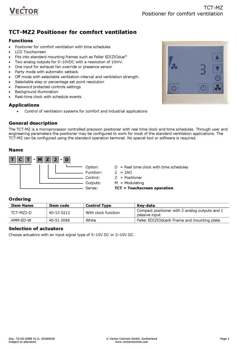
Vector TCT-MZ User manual

Vector

Vector TCT-MZ User manual

Vector TCY-MZ User manual

Vector

Vector TCY-MZ User manual

Vector TCY-MZ User manual

Vector

Vector TCY-MZ User manual

Popular Valve Positioner manuals by other brands

Spirax Sarco PP 5 Series Installation and maintenance instructions

Spirax Sarco

Spirax Sarco PP 5 Series Installation and maintenance instructions

Flowserve Logix 3000MD Series Technical bulletin

Flowserve

Flowserve Logix 3000MD Series Technical bulletin

Siemens SIPART PS2 manual

Siemens

Siemens SIPART PS2 manual

Incra LS Positioner owner's manual

Incra

Incra LS Positioner owner's manual

Siemens SITRANS VP300 operating instructions

Siemens

Siemens SITRANS VP300 operating instructions

ABB TZIDC Commissioning instructions

ABB

ABB TZIDC Commissioning instructions

halstrup-walcher PS 3 EIP Series instruction manual

halstrup-walcher

halstrup-walcher PS 3 EIP Series instruction manual

SMC Networks Chryssafidis P8001 Series Installation and maintenance manual

SMC Networks

SMC Networks Chryssafidis P8001 Series Installation and maintenance manual

Physik Instrumente M-06 Series Short instructions

Physik Instrumente

Physik Instrumente M-06 Series Short instructions

PI P-5 7 Series manual

PI

PI P-5 7 Series manual

ABB TZIDC-200 manual

ABB

ABB TZIDC-200 manual

Absolute Process Instruments APD 3280 quick start guide

Absolute Process Instruments

Absolute Process Instruments APD 3280 quick start guide

API API 3200 G Series instructions

API

API API 3200 G Series instructions

ARCA 824 series operating manual

ARCA

ARCA 824 series operating manual

Peaktronics 92 Series Installation, operation and maintenance manual

Peaktronics

Peaktronics 92 Series Installation, operation and maintenance manual

Westlock K20 operating manual

Westlock

Westlock K20 operating manual

Burkert 8635 Additional instructions

Burkert

Burkert 8635 Additional instructions

YASKAWA Motoman MH Series manual

YASKAWA

YASKAWA Motoman MH Series manual

manuals.online logo
manuals.online logoBrands
  • About & Mission
  • Contact us
  • Privacy Policy
  • Terms and Conditions

Copyright 2025 Manuals.Online. All Rights Reserved.