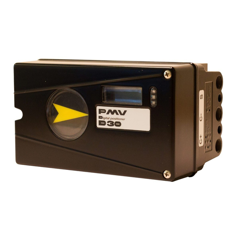
DeZurik PMV P36C User manual

PMV P36C AND P41C
POSITIONERS
USED WITH DeZURIK PNEUMATIC
ACTUATORS
Instruction D10327
August 2012

DeZURIK
PMV P36C and P41C Positioners
used with DeZURIK Pneumatic Actuators
D10327 © 2012 DeZURIK, Inc.
Instructions
These instructions provide information about Models P36C and P41C PMV Positioners. They are for
use by personnel who are responsible for installation, operation and maintenance of Models P36C and
P41C PMV Positioners.
Safety Messages
All safety messages in the instructions are flagged with an exclamation symbol and the word Caution,
Warning or Danger. These messages indicate procedures that must be followed exactly to avoid
equipment damage, personal injury or death. Safety label(s) on the product indicate hazards that can
cause equipment damage, personal injury or death. If a safety label becomes difficult to see or read, or
if a label has been removed, please contact DeZURIK for replacement label(s).
Personnel involved in the installation or maintenance of valves should be constantly alert to
potential emission of pipeline material and take appropriate safety precautions. Always wear
suitable protection when dealing with hazardous pipeline materials. Handle valves that have
been removed from service with the assumption of pipeline material within the valve.
Inspection
Your positioner has been packaged to provide protection during shipment; however, it can be damaged
in transport. Carefully inspect the unit for damage upon arrival and file a claim with the carrier if damage
is apparent.
Parts
Order parts from your local DeZURIK sales representative, or directly from DeZURIK. When ordering
parts, please include the 7-digit part number and 4-digit revision number (example: 9999999R000)
located on the data plate attached to the valve assembly. Also include the part name, the assembly
drawing number, the balloon number and the quantity stated on the assembly drawing.
DeZURIK Service
DeZURIK service personnel are available to install, maintain and repair all DeZURIK products.
DeZURIK also offers customized training programs and consultation services.
For more information, contact your local DeZURIK sales representative or visit our website at
www.dezurik.com.

DeZURIK
PMV P36C and P41C Positioners
used with DeZURIK Pneumatic Actuators
August 2012 Page 3 D10327
Table of Contents
Technical Specifications - - - - - - - - - - - - - - - - - - - - - - - - - - - - - - - - - - - - - - - - - - - - 4
Description - - - - - - - - - - - - - - - - - - - - - - - - - - - - - - - - - - - - - - - - - - - - - - - - - - - - - - 5
Operation - - - - - - - - - - - - - - - - - - - - - - - - - - - - - - - - - - - - - - - - - - - - - - - - - - - - - - - 5
Cam Selection - - - - - - - - - - - - - - - - - - - - - - - - - - - - - - - - - - - - - - - - - - - - - - - - - - - 6
Installation
Air Requirements - - - - - - - - - - - - - - - - - - - - - - - - - - - - - - - - - - - - - - - - - - - - - - -
Air Connections - - - - - - - - - - - - - - - - - - - - - - - - - - - - - - - - - - - - - - - - - - - - - - - -
I/P Unit Electrical Connections - - - - - - - - - - - - - - - - - - - - - - - - - - - - - - - - - - - - - -
Front Cover and Indicator Cover - - - - - - - - - - - - - - - - - - - - - - - - - - - - - - - - - - - - -
6
6
7
7
Reversing the Positioner Action - - - - - - - - - - - - - - - - - - - - - - - - - - - - - - - - - - - - - - - 8
Cam Adjustment - - - - - - - - - - - - - - - - - - - - - - - - - - - - - - - - - - - - - - - - - - - - - - - - - - 9
Zero and Span Adjustment
Span Adjustment - - - - - - - - - - - - - - - - - - - - - - - - - - - - - - - - - - - - - - - - - - - - - - -
Zero Adjustment - - - - - - - - - - - - - - - - - - - - - - - - - - - - - - - - - - - - - - - - - - - - - - -
9
9
Resetting the Range Spring - - - - - - - - - - - - - - - - - - - - - - - - - - - - - - - - - - - - - - - - - - 10
Indicator Adjustment - - - - - - - - - - - - - - - - - - - - - - - - - - - - - - - - - - - - - - - - - - - - - - -
Adjusting Travel Speed Dampers - - - - - - - - - - - - - - - - - - - - - - - - - - - - - - - - - - - -
10
10
I/P Electric Control Unit, P41C
The I/P Unit - - - - - - - - - - - - - - - - - - - - - - - - - - - - - - - - - - - - - - - - - - - - - - - - - - -
Filter - - - - - - - - - - - - - - - - - - - - - - - - - - - - - - - - - - - - - - - - - - - - - - - - - - - - - - - -
11
11
Installing I/P Unit On Positioner - - - - - - - - - - - - - - - - - - - - - - - - - - - - - - - - - - - - - - - 12
Maintenance for Positioners
Pilot Valve - - - - - - - - - - - - - - - - - - - - - - - - - - - - - - - - - - - - - - - - - - - - - - - - - - - -
Diaphragm - - - - - - - - - - - - - - - - - - - - - - - - - - - - - - - - - - - - - - - - - - - - - - - - - - - -
Feedback Spring - - - - - - - - - - - - - - - - - - - - - - - - - - - - - - - - - - - - - - - - - - - - - - - -
Balance Arm - - - - - - - - - - - - - - - - - - - - - - - - - - - - - - - - - - - - - - - - - - - - - - - - - - -
Lower Arm - - - - - - - - - - - - - - - - - - - - - - - - - - - - - - - - - - - - - - - - - - - - - - - - - - - -
O-Ring - - - - - - - - - - - - - - - - - - - - - - - - - - - - - - - - - - - - - - - - - - - - - - - - - - - - - - -
14
14
15
15
Troubleshooting - - - - - - - - - - - - - - - - - - - - - - - - - - - - - - - - - - - - - - - - - - - - - - - - - - 17
Parts - - - - - - - - - - - - - - - - - - - - - - - - - - - - - - - - - - - - - - - - - - - - - - - - - - - - - - - - - - 19

DeZURIK
PMV P36C and P41C Positioners
used with DeZURIK Pneumatic Actuators
D10327 Page 4 August 2012
Technical Specifications
Model P36C Both Models Model P41C
Input signal 20–100 kPa 3–15 psi
4–20mA
Linearity =<0,5% a=<0,75% a
Hysterisis =<0,75% a=<1%
Repeatability =<0,5% a=<0,5% a
Gain factor at 80%
load. (Supply: 87 psi)
1000 (kPa/kPa)
1000 (psi/psi)
Gain factor at 50%
load. (Supply: 87 psi)
1250 (kPa/kPa)
1250 (psi/psi)
Air consumption at
supply pressure: ±20% ±20%
0,2 MPa/29 psi 5,4 nl/min 0.19 SCFM
6,1 nl/min 0.22 SCFM
0,4 MPa/58 psi 12,3 nl/min 0.43 SCFM 13,6 nl/min 0.48 SCFM
0,6 MPa/87 psi 20 nl/min 0.71S CFM 22 nl/min 0.78 SCFM
0,8 MPa/116 psi 27,8 nl/min 0.98 SCFM 30,5 nl/min 1.08 SCFM
1 MPa/145 psi 35,7 nl/min 1.26 SCFM 39 nl/min 1.38 SCFM
Air delivery at
Supply pressure:
±20%
0,2 MPa/29 psi 135 nl/min 4.7 SCFM
0,4 MPa/58 psi 250 nl/min 8.7 SCFM
0,6 MPa/87 psi 360 nl/min 12.6 SCFM
0,8 MPa/116 psi 480 nl/min 16.8 SCFM
1 MPa/145 psi 590 nl/min 20.6 SCFM
Supply Pressure Max 1 MPa 145 psi 0,15–1 MPa 8–145 psi
Temperature Range
-15°C to +85°C
(5°F to 185°F)
Connector threads 1/4" NTP or G
Gauge threads 1/8" NTP or G
Weight std. 1,1 kg 2.4 lbs
1,6kg 3.5 lbs
Weight with gauges 1,3 kg 2.9 lbs 1,8 kg 4 lbs
Ingress Protection IP 65/NEMA 4
a. Percent of full scale.

DeZURIK
PMV P36C and P41C Positioners
used with DeZURIK Pneumatic Actuators
August 2012 Page 5 D10327
Description
The positioner is a precision instrument which, when used in conjunction with a DeZURIK actuator, can
provide the exacting control necessary to satisfy the most demanding process requirements.
The model P36C will accept a 3-15psi, 3-9psi, or 9-15 psi input signal.
The model P41C will accept either a 0-20mA or a 4-20mA input signal.
The modular design allows for easy parts replacement, and quick access to Zero and Span
adjustments. The housing uses an O-ring seal that can be adjusted to a sealed or drained position.
Operation
P36C and P41C positioners operate on a force balance principal. Force is applied from a signal
pressure that is transmitted through a diaphragm (1) to the balance arm (2). The feedback spring (3)
provides the opposing force. This force is proportional to the level of the lower arm (4). The lower arm
level is determined by the position of the cam (5), which is secured to the spindle (6). The spindle is
connected to the actuator shaft thus providing the feedback from the actuator and valve. See Figure 1.
When the opposing forces are equal, the balance arm (2) and the spool in the pilot valve (7) are in
neutral position and the complete system is in a balanced condition.
Figure 1 –Internal Parts
Air is supplied through port S to the pilot valve, which controls air flow through ports C1 and C2.
Starting from a balanced condition, an increased control pressure will deflect the diaphragm (1) down,
compressing the feedback spring (3). The balance arm (2) moves the spool (7) in the pilot valve (8)
thus supplying air to the actuator. At the same time air is exhausted from the actuator and vented to
atmosphere through the pilot valve and the OUT port.
Air pressure to the actuator is increased, causing the actuator to move the valve and the positioner
spindle (6). The spindle and cam (5) rotate, forcing the lower arm upward, compressing the feedback
spring (3). This motion continues until the two forces are equal and the system returns to a balanced
condition.

DeZURIK
PMV P36C and P41C Positioners
used with DeZURIK Pneumatic Actuators
D10327 Page 6 August 2012
Cam Selection
Each cam is designed to provide split range instrument signals. Standard cam characterization is linear;
however, other characterizations are available.
Installation
Positioners installed in hazardous areas can be ignition sources. Ensure positioners used in
hazardous areas have proper fire/explosion ratings.
Air Requirements
Maximum positioner supply pressure is 145 psi (1 MPa).
Supply air must be clean, dry and free from oil, water, moisture, dirt and debris. The air should be
freeze-dried or similar to a dew point of at least 18 degrees F (10°C) below lowest ambient
temperature.
A 30 micron (or finer) filter/regulator should be installed as close to the positioner as possible to ensure
proper supply air quality.
Air Connections
Air connections are for 1/4" NPT male connectors and are marked on the positioner. Gauge ports are
for 1/8" NPT.
DeZURIK recommends Loctite® 577 tape or similar for sealing.
Port I Input instrument pneumatic signal 3-15 psi (20-100kPa)
Port S Supply air, maximum 145 psi (1 MPa), minimum 21 psi
(0.15 MPa) for P41C
Port C1, C2 Actuator connections. C2 opening port
OUTLET Exhaust air port. Do not plug.
Port IpGauge port for pneumatic input signal (P36C).
Port IEInput electric signal (4–20 mA) (P41C)
Port P Gauge port for I/P unit output pressure (P41C)
Figure 2 - Connecting Block

DeZURIK
PMV P36C and P41C Positioners
used with DeZURIK Pneumatic Actuators
August 2012 Page 7 D10327
Installation (Continued)
The outlet port is used for venting the positioner. All air from the positioner, actuator and I/P unit is
vented to atmosphere through this port. Do not plug this port. A high flow silencer or an exhaust pipe
can be connected to the outlet port to prevent foreign objects from entering and blocking the exhaust.
When using gas for supply, please contact. Port I should be plugged on the P41C. For single acting
operation, plug port C1 for increasing signal to OPEN, or C2 for increasing signal to CLOSE.
Note: See Figure 4 for proper cam position.
With the I/P unit mounted, the positioner is supplied with air from port S and does not need an external
air supply. See pages 8–11 for more information on the I/P unit.
I/P Unit Electrical Connections
Electrical connection on I/P unit accepts 1/2" NPT or PG 13,5 cable gland.
See Figure 10E for wiring connections. Maximum recommended wire size is 16 AWG.
Front Cover and Indicator Cover
The front cover is secured to the pneumatic positioner with four captive screws and sealed with an O-
ring (1). This sealing system allows for complete sealing or draining of the positioner by changing the
position of the O-ring. The O-ring system is common to the Pneumatic positioner, I/P unit and
Feedback unit in the Valve Control System.
The O-ring can be looped over notches (2) in the front cover to allow for drainage. There are eight
locations on the front cover where the O-ring can be looped. See Figure 3.
Figure 3 –Front Cover and Indicator Cover
The indicator cover (3) is O-ring sealed and secured by a bayonet coupling. The indicator cover is also
used to secure the identification cover (4).
To remove the indicator cover turn it slightly counterclockwise until it loosens. Once loosened, the
identification cover and O-ring (5) can be removed. When installing the indicator cover and identification
cover ensure the O-ring is properly sealed.

DeZURIK
PMV P36C and P41C Positioners
used with DeZURIK Pneumatic Actuators
D10327 Page 8 August 2012
Reversing the Positioner Action
To change the positioner action from increasing signal to OPEN to increasing signal to CLOSE, or vice
versa, follow the steps below.
Moving parts from accidental operation of power actuator can cause personal injury or
equipment damage. Disconnect and lock out power to the actuator before servicing.
1. Shut off the supply air pressure and the input signal pressure.
2. On double-acting cylinders, disconnect and reverse the two connections to positioner ports C1
and C2. For spring-return cylinders, proceed to step 3.
3. Remove the positioner cover and dial indicator.
4. Loosen the cam locking nut screw and remove the cam locking nut.
5. Turn the cam over and position the cam so the cam roller is about 1/32" from the stop on the
cam. See Figure 4.
Figure 4 –Cam Positions
6. Tighten the locking screw — allow room for movement of the cam as the cam locking nut is
tightened.
7. Turn on the supply and input pressures and operate the valve.
8. Adjust the zero and span adjustments, if necessary.

DeZURIK
PMV P36C and P41C Positioners
used with DeZURIK Pneumatic Actuators
August 2012 Page 9 D10327
Cam Adjustment
Figure 5 –Cam Adjustment
1. With the cover and indicator removed, loosen the screw (1) and turn the cam locking nut (2)
counterclockwise until the cam loosens. See Figure 5.
2. Adjust the cam (3) as desired, making sure the ball bearing (4) is always riding on an active lobe
on the cam.
3. Finger tighten the locking nut and tighten the screw (1).
Note: Ensure screw (1) is loose from the cam before tightening locking nut (2).
4. Install and adjust the indicator, and install cover.
Zero and Span Adjustment
Span Adjustment
Span is adjusted with the yellow (upper) thumb wheel (1)
located on the feedback spring. See Figure 6. To adjust
the span, loosen the locking screw (2) and turn the yellow
thumb wheel. Do not allow the top of the spring to contact
the spring guide (3). When span is set, tighten the locking
screw. Always check Zero after adjusting Span.
Zero Adjustment
Zero is adjusted by turning the silver (lower) thumb wheel
(4) located on the lower arm (5). It can also be adjusted
externally with a screwdriver (7), through the zero adjust
opening. Remember to re-install the zero adjust cover (6)
to keep the unit clean.
Figure 6 –Zero and Span Adjustment

DeZURIK
PMV P36C and P41C Positioners
used with DeZURIK Pneumatic Actuators
D10327 Page 10 August 2012
Resetting the Range Spring
If the correct span cannot be obtained after 2 or 3 zero/span adjustments, reset the range spring as
follows:
1. Disconnect air supply and remove the range spring from the positioner.
2. Loosen screws (1 and 2).
3. Adjust the collar so it is 3/16" or 9/32"* below the flange face.
*Depending on spring style—see Figure 7
Figure 7 –Spring Styles
4. Adjust the spring end to 1/32" clearance.
5. Tighten screws (1 and 2).
6. Adjust the lower zero screw so that 1 or 3 threads are showing (depending on spring style).
7. Reinstall the range spring assembly.
Indicator Adjustment
To adjust the indicator, remove front cover and pull the
indicator upward until it comes off the Allen screw. Before
installing the indicator make sure the Allen screw is
tightened. Press the indicator on the screw and adjust it
by rotating clockwise into position.
Adjusting Travel Speed Dampers
The dampers (5) located on the connecting block provide
a simple means of adjusting the actuator travel speed.
See Figure 8.
For double acting actuators, set the damper marked
Supply to fully open and adjust only the damper marked
Outlet.
For single acting actuators, adjust both the Supply and
Outlet dampers for operation.
Figure 8 –Speed Dampers

DeZURIK
PMV P36C and P41C Positioners
used with DeZURIK Pneumatic Actuators
August 2012 Page 11 D10327
I/P Electric Control Unit, P41C
The I/P Unit
The I/P unit is mounted directly on top of the positioner. Span and Zero for the I/P converter are factory
set. No external air supply is needed, as the I/P unit is supplied with air from the positioner. The I/P unit
accepts a 4–20 mA input signal. (Other ranges are available on request.)
Positioners installed in hazardous areas can be ignition sources. Ensure positioners used in
hazardous areas have proper fire/explosion ratings.
Filter
The filter plug can blow out and cause injury or damage if it is removed while under pressure.
Do not remove the filter plug when the positioner is pressurized.
The I/P unit is equipped with a built in filter. The threaded filter plug can easily be removed for
replacement. During replacement, always check the filter compartment, and clean if necessary. Make
sure the filter plug O-ring is in good condition.

DeZURIK
PMV P36C and P41C Positioners
used with DeZURIK Pneumatic Actuators
D10327 Page 12 August 2012
Installing I/P Unit On Positioner
Positioners installed in hazardous areas can be ignition sources. Ensure positioners used in
hazardous areas have proper fire/explosion ratings.
1. Turn off the supply air and remove the connecting block (1), gauge or plug from port IP, and the
existing gasket (4) between the positioner (2) and connecting block. See Figure 9.
2. Carefully install the new gasket supplied with the I/P unit.
Figure 9 –Installing I/P Electric Control Unit P41C
3. Ensure the relief valve spring (5) is installed properly.
4. Install the connecting block on the Positioner, and plug port I.
5. Remove cover on I/P unit.

DeZURIK
PMV P36C and P41C Positioners
used with DeZURIK Pneumatic Actuators
August 2012 Page 13 D10327
Installing I/P Unit On Positioner (Continued)
6. Install the I/P unit on the top of the positioner, making sure the four O-rings are in the correct
places. See Figure 10b.
7. Tighten the I/P unit with the three screws. See Figure 10a.
Figure 10 –I/P Unit On Positioner
8. Connect input signal cable to port lE and tighten the cable gland (see Figure 10e).
9. Adjust the O-ring on the I/P unit housing to desired position; sealed or drained (see Figure 10c).
10. Install a plug or a gauge in port P, and make sure the filter plug is tightened (see Figure 10d).

DeZURIK
PMV P36C and P41C Positioners
used with DeZURIK Pneumatic Actuators
D10327 Page 14 August 2012
Maintenance for Positioners
Pilot Valve
To remove the pilot valve for cleaning:
1. Remove the screw (1) and carefully lift out the
complete assembly (2).
2. Gently remove the spool (3) from the block.
3. Clean the parts, using methylate cleaner or
similar.
4. Blow the parts dry with compressed air.
Note: If the parts show signs of wear, replace
the assembly. Do not mix parts from other
assemblies.
5. Check the O-rings, then secure and install the
pilot valve assembly to the positioner and
secure it with the screw (1).
6. Ensure the leaf spring (4) on the balance arm (5) is properly fitted in the groove on the spool (6).
7. Check again to ensure smooth operation of the assembly.
Diaphragm
On P41C positioners the I/P unit must be removed
to reach the diaphragm. See Figure 12.
1. Loosen screws (1), remove the diaphragm
cover (2).
2. Loosen screw (3), then remove diaphragm
(4) and washers (5).
3. When installing the diaphragm, place one
washer on each side of the diaphragm.
Ensure the raised circle on the washers is
facing the diaphragm.
4. Install the screw (3) and tighten.
5. Check the O-ring on the diaphragm cover
(2), then install and secure the cover with
screws (1).
Figure 11 –Location of Pilot Valve Spool
Figure 12 –Diaphragm Removal and
Installation

DeZURIK
PMV P36C and P41C Positioners
used with DeZURIK Pneumatic Actuators
August 2012 Page 15 D10327
Maintenance for Positioners (Continued)
Feedback Spring
Once the front cover and indicator are removed, the feedback spring can be easily reached. See Figure
13.
1. Hold the spring (1) from the top, pull down and
out.
2. When installing, hold the assembly at the top,
guide the lower part to position on the zero
screw, then press down until it fits easily under
the balance arm (2).
3. Ensure the assembly is aligned properly against
the balance arm.
Balance Arm
The balance arm can only be removed after I/P unit, diaphragm and feedback spring have been
removed. See Figure 14.
Refer to "Diaphragm" and "Feedback" sections above.
1. Loosen the screws (3) and remove the balance
arm.
2. When installing the balance arm make sure the
leafspring (4) on the underside of the balance
arm (5) is properly engaged in the groove (6) of
the spool in the pilot valve.
3. Tighten the two screws (3) holding the balance
arm to the positioner.
Figure 13 –Feedback Spring Access
Figure 14 –Balance Arm Access

DeZURIK
PMV P36C and P41C Positioners
used with DeZURIK Pneumatic Actuators
D10327 Page 16 August 2012
Maintenance for Positioners (Continued)
Lower Arm
After the front cover has been removed, the lower arm can be easily reached. See Figure 15.
Figure 15 –Lower Arm
1. Remove the indicator, feedback spring and the cam.
2. Loosen screw (2) and remove twist stop (1).
3. Remove screw (3), lower arm (4), rod (5) and spring (6).
4. Check rod and lower arm for wear, and replace if necessary.
5. Clean the rod and install it in the lower arm.
Note: The lower arm should move easily and smoothly.
6. Install the lower arm and rod assembly into the positioner housing, making sure the spring (6) is
attached properly to the lower arm and positioner housing.
7. Secure the lower arm and rod assembly with the screw (3).
8. Check again that the lower arm moves smoothly.
9. Apply a small amount of grease on the small tongue on the lower arm, then install and secure
the twist stop.
10. Install the cam, feedback spring, indicator and front cover.
O-Rings
With time and use, O-rings can become brittle. This can cause poor operation or failure. Always check
O-rings when performing work on the positioner, and replace any brittle O-rings.
Note: A thin layer of silicon grease applied on the O-rings prolongs their life.

DeZURIK
PMV P36C and P41C Positioners
used with DeZURIK Pneumatic Actuators
August 2012 Page 17 D10327
Troubleshooting
Condition Possible Cause Corrective Action
Signal change has no effect on
actuator position.
Indicator is loose. Check indicator and screw.
Re-position indicator and
tighten.
Air supply is not adequate. Check air supply to positioner,
and tubing to actuator.
Input signal is fluctuating. Check input signal. Repair or
replace wiring.
Diaphragm is damaged. Check diaphragm for damage or
leakage. Repair or replace
diaphragm.
Pilot valve is dirty or worn. Check pilot valve function. Clean
or replace pilot valve.
Cam is incorrectly positioned. Check cam for correct setting.
Signal change results in actuator
running to end position
Positioner is loose. Check coupling between
positioner and actuator.
Cam is loose. Check cam position and locking
screw.
Input signal is fluctuating. Check input signal. Repair or
replace wiring.
Inaccurate Positioning
Pilot valve is dirty or worn. Check pilot valve function. Clean
or replace pilot valve.
Diaphragm is damaged. Check diaphragm; repair or
replace diaphragm.
Input signal is fluctuating. Check input signal. Repair or
replace wiring.
Actuator is not sized correctly. Check sizing. Replace with
correct actuator.
Valve torque is increased from
wear or damage.
Rebuild or replace valve.

DeZURIK
PMV P36C and P41C Positioners
used with DeZURIK Pneumatic Actuators
D10327 Page 18 August 2012
Figure 16 –Positioner Configurations

DeZURIK
PMV P36C and P41C Positioners
used with DeZURIK Pneumatic Actuators
August 2012 Page 19 D10327
Parts
Table A: Parts - Positioner
Part No. Qty Description
1 1 Housing
2 1 Front cover with O-ring
3 1 Connecting block a
4 1 Relief valve spring
6 1 Gasket P5 a
7 1 Diaphragm cover with O-ring
8 1 Diaphragm
9 2 Diaphragm washer
10 1 Balance arm
13 1 Feedback spring b
18 1 Lower arm assembly
19 1 Rod
20 1 Spring
21 1 Indicator: arrow, flag, or
pointer
22 1 Indicator Cover c
24 1 Twist stop
25 1 Pilot valve with O-rings
26 1 Shaft with O-rings and screw
27 1 Cam locking nut
29 1 Zero cover
30 1 Cover
32 11 Ball bearing
35 1 Identification cover
a. Specify 1/4" NTP or G.
b. Specify 3–15 psi or 6–30 psi Spring Assembly.
c. Specify Flag, Transparent or Opaque.
Table A: Parts – Positioner, continued
Part No. Qty Description
36 4 Plug a
37 1 Cam
38–45 1 Screw set
46–53 1 O-ring set
54 1 Spindle adaptor
a. Specify 1/8” NTP or G.
Table B: Parts – I/P Unit
Part No. Qty Description
61 1 I/P box
62 1 I/P cover with screws
63 1 I/P nose assembly a
64 1 Relief valve spring
65 1 Filter and plug
66 1 Filter (5 nos)
67 1 I/P Gasket
70 1 O-ring
71 1 I/P converter
73 1 Round I/P mounting
bracket with hardware
74 1 I/P enclosure with
converter b
a. Specify 1/4" NTP or G.
b. Specify Std., Cenelec (flameproof), or
Explosion Proof FM.
This manual suits for next models
1
Table of contents
Other DeZurik Valve Positioner manuals
Popular Valve Positioner manuals by other brands

Samson
Samson TROVIS 3731-3 Mounting and operating instructions

Fisher
Fisher 4000 instruction manual
Power-Genex
Power-Genex SS3SL Series Instructions and operating manual

Will Burt
Will Burt ACCUPOINT AP-8 Operator's manual
Baker Hughes
Baker Hughes Masoneilan SVI II AP instruction manual
Siko
Siko AP09 User information


