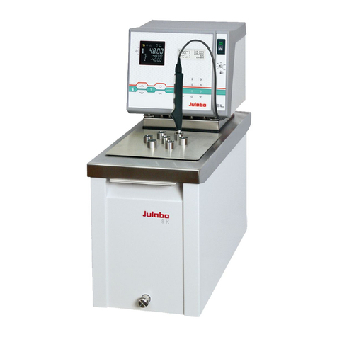
Berkeley Varitronics Systems Cicada User manual

manual version 1.2
manual version 1.2
Cicada

Contents
CICADA ACCESSORIES................................................................................................. 3
CICADA KEYPAD......................................................................................................... 3
GETTING STARTED...................................................................................................... 3
AP MEASUREMENT SCREENS......................................................................................... 4
MAIN MENU.............................................................................................................. 5
AP ANALYSIS............................................................................................................ 5
AP FOLLOWING......................................................................................................... 5
SPECTRUM............................................................................................................... 6
PEAK HOLD.............................................................................................................. 6
CICADA SETUP........................................................................................................... 6
INFO SCREEN............................................................................................................ 7
GPS : ON................................................................................................................. 7
INITIALIZE CARD........................................................................................................ 8
SELECT REGION......................................................................................................... 8
CONTRAST ADJUSTMENT.............................................................................................. 9
BACKLIGHT ADJUSTMENT............................................................................................. 9
WEP ENCRYPTION DETECTION....................................................................................... 9
NETWORKING BASICS.................................................................................................. 10
CICADA ACCESSORIES................................................................................................. 12
DIRECTION FINDING ANTENNA SETUP.............................................................................. 13
CICADA SERIAL INTERFACE (DATA LOGGER)...................................................................... 14
SYSTEM REQUIREMENTS.............................................................................................. 14
GPS SCREEN............................................................................................................. 15
SERIAL PORT SCREEN................................................................................................. 15
UNIT SETUP SCREEN................................................................................................... 16
DOLPHIN REAL TIME PLOTTER SCREEN............................................................................ 16
MENU SELECTIONS..................................................................................................... 17
AP ANALYSIS SCREEN................................................................................................. 19
FOLLOW SCREEN....................................................................................................... 19
SPECTRUM SCREEN.................................................................................................... 20
CHAMELEON WLAN DATA CONVERSION APPLICATION.......................................................... 21
GLOSSARY OF ACRONYMS........................................................................................... 23
GENERAL SAFETY
ANTENNA RADIATION PATTERNS
CICADA DATA SHEET
INTRUDER ALERT: Recognizing WLAN Attacks & Locating the Culprits (MPD August, 2002)
802.11a Measurement Techniques and Network Issues (MPD November, 2003)
TAKE THE WLAN TEST CHALLENGE (COMMUNICATION NEWS April, 2002)
Page 1

Page 2
Cicada™ is a handheld, wireless receiver designed spe-
cifically for sweeping and optimizing Local Area Networks.
The instrument measures coverage of direct sequence
CDMA networks which operate on the IEEE 802.11b stan-
dard allowing the user to measure and determine the
AP (Access Point), PER (Packet Error Rate), and RSSI
signal levels and access points throughout a building.
Cicada detects and differentiates from narrow-band mul-
tipath interferences such as microwave ovens and direct
sequence systems and features a built-in display, keypad
and removable battery pack for true portability.
Cicada’s battery pack uses common AA battery cells found
in any conveinence store. Ni-Cad, Alkalines, Ni-MH and
Li-Ion cells may all be used. Cicada does require 5 AA
cells with at least 1500 mAh per cell. BVS supplies 2 bat-
tery packs complete with 10 Ni-MH battery cells to get
users working right out of the box. Ni-MH cells are recom-
mended for best performance from your Cicada.
Cicada also includes a simple 2.4 GHz threaded antenna
that screws right into the top of the unit. Additional anten-
nas may be ordered from BVS through BVS.
At the top of the Cicada rests the GPS connector, antenna
connector and upload port. The GPS antenna connector
(left) is a small male connector. The antenna connector
(center) is a 2.4 GHz SMA Female 50 ohm. The provided
antenna easily screws and unscrews from this connec-
tor. Be sure to unscrew antennas when transporting the
Cicada. The upload port (right) is used as a one way
communications port for uploading new firmware to the
Cicada. The port uses the provided cable which employs a
standard RJ-11 phone jack on one end and DB-9 PC serial
cable on the other end.
See UPDATING CICADA FIRMWARE in this manual for firm-
ware updating procedures.

Page 3
CICADA ACCESSORIES
Your Cicada includes all basic operational accessories includ-
ing the following: 2.4 GHz antenna, GPS antenna, 16MB com-
pact flash card, compact flash card reader, 2 (Ni-MH) battery
packs, AC/DC power cable, carrying case and upload cable.
Insert depleted battery pack into charger and plug charger into
AC outlet. See rear of charger for LED status indicator lights.
Approximate charging time for included Ni-MH battery pack is
just over one hour. Run time using these same batteries is just
over two hours.
NOTE: The included charger may only be used to charge the
included Ni-MH batteries or other AA Ni-MH batteries. NOT
Ni-CAD batteries. Batteries are automatically conditioned in
the charger before starting a rapid charge. The charge and
runtime are balanced so that the charge is usually complete
before the Cicada displays low battery indication. This is
an average estimate since the current consumed by Cicada
and runtime depend substantially on the mode of operation.
Expect over 500 cycles from each Ni-MH pack.
CICADA KEYPAD
Cicada uses a raised plastic keypad as its only interface. Below
are simple descriptions of the buttons and their features:
LOGGING - indicates if unit is logging to compact flash
RECEIVE - indicates if any signals are being received
GPS POWER - indicates internal GPS ON / OFF status
1 - toggles backlight ON & OFF
POWER - toggles Cicada ON & OFF
4 - toggles highest signal strength metering ON & OFF
5 - toggles data logging ON & OFF to compact flash
SETUP - enters the setup menu screen
7 - incrementally time stamps
ESC - exits current menu screen
0 - displays contrast screen
ENT - executes currently selected option
UP/DOWN ARROWS - scroll through selections
GETTING STARTED
Operation of the Cicada is straightforward. Insert 5 fresh bat-
tery cells into removable pack. Close the bottom back up and
power on the Cicada by holding down the POWER button for
about 2 seconds.

Page 4
AP MEASUREMENT SCREENS
This is the main measurement screen used for monitoring
and selecting any valid FHSS (Frequency Hopping Spread
Sprectrum) APs (Access Points). This screen displays AP
parameters such as signal strength in dBm, WEP encryp-
tion, current GPS time/position/satellites of Cicada and MAC
address list. The MAc address list consists of all FHSS MAC
addresses detected. Multiple addresses may be listed and
monitored simultaneously here. Use the UP/DOWN ARROW
keys to toggle between all of these selections and ENT to
choose one. Upon choosing an AP, the user will be taken to
the AP Following Screen (below) providing detailed param-
eters for the chosen AP.
AP ANALYSIS SCREEN
NAEur - indicates current region selection for measure
The AP address window at the bottom indicates all IEEE
addresses indentified. (the arrow to the left indicates the
address that is currently selected)
dBm - indicates the signal strength of the last packet mea-
sured.
W - indicates WEP (Wireless Equivalent Privacy). “P” indi-
cates encryption is detected.
LAT - GPS Latitude coordinates
UTC - GPS time stamp
LON - GPS Longitude coordinates
SAT - number of satellites in view
Indicates compact flash has been formatted for Cicada
Indicates data storage remaining in compact flash card
AP FOLLOWING SCREEN
AP: the selected AP’s MAC address
RSSI: last packet’s signal strength measurement in dBm
Hop Set: indicates set number of sets 1,2 or 3
Hop Pattern: indicates pattern number of patterns 1-79
(note: this number corresponds to the IEEE 802.11 spec)
Dwell Time: indicates how long the AP stays on a channel
before it jumps to another channel in TU (Time Units defined
as 1024 microseconds)
TSF: Timing Synchronization Function indicates the AP’s abso-
lute time that counts down to the next channel hop
SSID: currently selected AP’s Service Set IDentification
PER: Packet ErrorRate percentage for the selected AP
Following - Cicada continues to follow AP as it hops

Page 5
MAIN MENU
Press the ESC key at any time to enter the MAIN MENU. This
menu allows access to all controls and parameters found in
the Cicada. Use the UP/DOWN ARROW keys to choose and
press ENT to make the selection.
AP ANALYSIS
This selection places a cursor at the bottom of the screen to
the left of the AP addresses. By pushing ENT, the user selects
(indicated by the arrowhead) a specific AP address to moni-
tor. Use Select AP and the UP / DOWN ARROW keys to toggle
through all received addresses. In this screen, the user may
access up to 16 unique, detected AP addresses by scrolling
through the list and selecting one.
AP FOLLOWING
By selecting an AP to monitor off the AP analysis screen, the
user will prompt this screen to appear. This screen allows
monitoring of the selected AP’s beacon timing channel. After
a few moments of searching, Cicada will “lock on” and follow
the AP’s timing parameters.The parameters are listed on page
4 of this manual. Press ESC at any time to return to the AP
analysis screen.

SPECTRUM
This RSSI screen indicates all received signals at 2.4 GHz in
a 1 MHz bandwidth that Cicada continuously scans. The peak
power is indicated graphically and numerically on this screen
as well as the channel being scanned.
PEAK HOLD
Peak Hold is only activated and deactivated in the Spectrum
Screen. Use Peak Hold when looking for interference sources
with low duty cycles such as APs. Push the 4 key on the keypad
to turn ON the Peak Hold. Push the 4 key again to turn the Peak
Hold back OFF. Each small tick mark indicates a dBm peak
for that portion of the 1 MHz scan. Remember the last signal
displayed will reset when Peak Hold is toggled ON.
CICADA SETUP
Press the SETUP key at antime to access the Setup Menu.
While in the this menu, use the UP/DOWN ARROW keys to
choose a setup option. From this menu, users may access
and/or control features such as unit information, internal GPS,
Compact Flash card and international region. Press ENTER to
select or ESC to return to previous menu screen.
Page 6

Page 7
INFO SCREEN
This informational screen provides information on your Cicada
unit such as firmware version, serial number and current GPS
information.
GPS : ON
Press ENTER to toggle the internal GPS ON and OFF. The GPS
POWER LED indicator above the keypad will light up indicating
the internal GPS is operational. Be sure that the GPS antenna
is connected to the Cicada and not blocked from the satellites
in the sky.
Allow a few minutes for the GPS antenna to acquire a few sat-
ellites and lock. Be sure to keep the GPS off if GPS data is not
needed in WLAN studies as it will draw power and shorten the
running time of your Cicada.

INITIALIZE CARD
Press ENTER to begin initialization of the compact flash card.
A warning screen will then appear asking the user to press
ESC or ENTER. Upon selecting ENTER, and new message will
appear moments later indicating that the compact flash card
is now formatted for use in your Cicada.
SELECT REGION
At anytime, press SETUP on the key pad to access the Select
Geographic Region screen. Use the ARROW keys and ENT to
select between one of the four IEEE allocated regions for scan-
ning.
Page 8

CONTRAST ADJUSTMENT
At anytime, press 0 on the key pad to access the Contrast
Adjustment screen. Use the UP/DOWN ARROW keys to
increase or decrease LCD contrast. When finished, press ESC
to exit this screen.
BACKLIGHT ADJUSTMENT
At anytime, press 1 key to toggle the backlght off and on.
Remember that using the Cicada without the backlight on will
increase overall battery life.
WEP ENCRYPTION DETECTION
A “P” next to its associated AP address and signal strength
indicates that WEP (Wireless Equivalent Privacy) is enabled
and deteced for that particular AP. An empty space indicates
no WEP encryption.
Page 9

Networking Basics
Packets and traffic
Information travels across a network in chunks called “packets.” Each packet has a header that tells where
the packet is from and where it’s going, similar to what you write on the envelope when you send a letter.
The flow of all these packets on the network is called “traffic.”
Hardware addresses
Your PC “listens” to all of the traffic on its local network and selects the packets that belong to it by check-
ing for its hardware address in the packet header or MAC (Media Access Control). Every hardware product
used for networking is required to have a unique hardware address permanently embedded in it.
IP addresses
Since the Internet is a network of networks (connecting millions of computers), hardware addresses alone
are not enough to deliver information on the Internet. It would be impossible for your computer to find its
packets in all the world’s network traffic, and impossible for the Internet to move all traffic to every net-
work, your PC also has an IP (Internet Protocol) address that defines exactly where and in what network
it’s located. IP addresses ensure that your local Ethernet network only
receives the traffic intended for it. Like the hierarchical system used to define zip codes, street names,
and street numbers, IP addresses are created according to a set of rules, and their assignment is carefully
administered.
Put another way, the hardware address is like your name; it uniquely and permanently identifies you. But it
doesn’t offer any clues about your location, so it’s only helpful in a local setting. An IP address is like your
street address, which contains the information that helps letters and packages find your house.
Rules for Sending Information (Protocols)
A protocol is a set of rules that define how communication takes place. For instance, a networking proto-
col may define how information is formatted and addressed, just as there’s a standard way to address an
envelope when you send a letter.
Networking Devices:
Bridges
A bridge joins two networks at the hardware level. This means that as far as other protocols are concerned,
the two networks are the same.
Routers
A router connects two IP networks. In contrast to a bridge, which joins networks at the hardware level, a
router directs network IP traffic based on information stored in its routing tables. A routing table matches
IP addresses with hardware addresses. The router stamps each incoming IP packet with the hardware
address that corresponds to that IP address. As a result, the packet can be picked up by the right computer
on the hardware network.
DNS (Domain Name Server)
Networks (domains) on the Internet have names that correspond to their IP addresses. A Domain Name
Server maintains a list of domain names and their corresponding addresses. This is why you can go to
Berkeley’s Web site by entering www.bvsystems.com, instead of the IP address.
Networking Terms:
Page 10

TCP/IP (Transport Control Protocol/Internet Protocol)
TCP/IP is a collection of protocols that underlies almost every form of communication on the Internet.
DHCP (Dynamic Host Control Protocol)
DHCP is a method of automatically assigning IP addresses. Instead of assigning addresses to individual
users, addresses are assigned by the DHCP server when clients need them. This means that instead of
entering several fields of long addresses, users need only to select DHCP as their configuration method
for IP networking.
PPP (Point-to-Point Protocol)
PPP is the most common protocol for providing IP services over a modem.
NAT (Network Address Translation)
NAT is used to share one IP address among several computers. A device set up as a NAT router uses a col-
lection of “private” IP addresses (in the range 10.0.1.2 to 10.0.1.254 for example) to allow several com-
puters to access the Internet using one “public” IP address. When a computer using a private IP address
requests information from the Internet, the NAT router keeps a record of the computer making the request,
and sends the information to the Internet using its own IP address. When the response comes back from
the Internet, the NAT router forwards the packet to the appropriate computer.
Page 11

Cicada
Accessories for your
PCMCIA Card Reader
Type I, II & III
P/N ATA-000
$ 45.00
GPS Antenna
GPS magmount active antenna with
SMC male connector
P/N GPS-SMC
$ 45.00
RS-232 Serial Cable
DB-9 Female to RJ-11
P/N 00002AB
$ 25.00
Ni-MH Battery Pack
5 AA 7.5 V
P/N NIMH-005
$ 45.00
Compact Flash Card
16 Megabytes
P/N 16MBATAF-C
$ 50.00
Ni-MH Battery Charger with switch-
ing transformer
P/N NIMH-000
$ 105.00
DC PowerCable Pack
Cigarette Lighter Adaptor
P/N 002NIMH
$ 50.00
Page 12
2.4 GHz Antenna
SMA connector
P/N SMA-001
$ 25.00
Direction Finding Antenna with
mounting bracket, cable &
type N SMA male
9 dBi gain
P/N DFA-000
$ 250.00
Rugged Carrying Case
ABS Plastic
P/N P-CASE
$ 100.00

Page 13
Optional Direction Finding Antenna (DFA-000) Setup
1 Remove cap from SMA connector on DF antenna.
2 Hook antenna bracket into slit on top of unit.
3 Slide bracket plate into other slit.
4 Tighten both screws on bracket.
5 Loop & screw in antenna cable to unit.

OVERVIEW
Cicada Program Requirements
V2.0 Cicada Data Logger requires the following:
Windows 98, Windows 2000 or Windows XP operating system
64 Meg (or more) RAM
Pentium II CPU
400 MHz or greater operating speed
100 MB (or more) free space on Hard Drive
At least 1 serial port for data logging (not required for replay)
Color Display 800 x 600 recommended
Optional PCMCIA card reader
The CICADA Serial Interface software allows complete control of the CICADA IEEE 802 scanner. All data
displayed on the CICADA LCD is also displayed on the PC screen. Data received by the PC software can be
saved in disk files for later replay and conversion. Each measurement screen of the CICADA is duplicated
by the PC software. In addition, GPS and UNIT INFORMATION screens are provided to display additional
information about the GPS receiver and the CICADA. When the PC software starts, data is displayed in a
640 by 480 format. To increase to 800 by 600, click the maximize button on the right side of the control bar.
The PC used to run the CICADA application MUST be running the Windows 98 or Windows 2000 operating
system. NO OTHER program should be running while the CICADA application is running.
The PC menu bar is used to select disk files for saving or replaying data files (SELECT DISK FILE).
Instructions can be found using the HELP menu selection. Version and other information is available via
the ABOUT selection. INCREMENT MARKER causes the CICADA connected to the PC to add one to the cur-
rent marker value. PEAK HOLD is used to toggle the peak hold feature on and off during the spectrum or
follow measurements. UNIT SETUP displays a screen that displays CICADA parameters. GPS displays the
gps receiver information screen.
Cicada GPS Status screen.
To view this screen, click the GPS Status Tool Bar button.
Page 14

GPS SCREEN
This screen is used to determine the number of satellites being tracked by the built in
GPS receiver. At least 3 satellites are required for GPS lock. The tool bar GPS Status
button indicates lock status with two indicators. These indicators are GREEN if the GPS
is locked, RED if not. If the indicators are the same color as the button, the Cicada GPS
is off.
This display is available during replay or while displaying real time data. It can be sized using the
mouse and the lower right hand corner of the GPS display. The color of the top line of this display
indicates GPS lock status. The same color is displayed by the indicators on the GPS Status tool bar but-
ton.
SERIAL PORT SCREEN
This is the first screen that the user will see when running Cicada Serial Interface. Simply connect the
Cicada unit to any available PC serial port with the provided cable, select the appropriately numbered port
on this menu screen and select OK. The Cicada is now connected to your PC for communications.
Page 15

UNIT SETUP SCREEN
Clicking the menu View Unit Data button will cause the Cicada connected to the PC serial port to send its
unit data which is displayed in a dialog.
When using BVS Dolphin plotting software, this information must be available. When
making data files that will be replayed for plotting, display this dialog just after turning
on Data save. Do the same to plot data in real time using Dolphin.
DOLPHIN REAL TIME PLOTTER SCREEN
When using the DOLPHIN plotter software with the CICADA, check the “Use BVS Dolphin” in the UNIT
SETUP screen. DOLPHIN plots data in real time or from data files during replay.
V2.0 Cicada PC Software Dolphin Support
Dolphin software requires that the Cicada serial number be recorded before it will operate. Use the follow-
ing steps to ensure that the Dolphin software has the Cicada serial number.
1 Run the supplied copy of BVS Dolphin before starting Cicada v2.0.
2 Start Cicada v2.0
Page 16

3 If connected to the Cicada via PC serial port, get the Cicada Setups by clicking the “View Unit Data ”
menu button. If using Dolphin later with replay, make sure to do this just after turning on the data file save
so that the Cicada serial number is recorded in the data save file.
4 Make sure the Cicada GPS is turned on.
Menu Selections
File: Use to select a Cicada data file to replay or to cancel the current disk file replay. The Exit
selection closes the application in the same way as the Close Button in the upper right hand corner of the
screen. Closing the application causes any open data files to be closed.
View: This selection can be used to turn on and off the tool bar. It is also used to get the Unit Data
from the currently connected Cicada. Unit data is required when using the BVS Dolphin plotting
software.
Help: Use this selection to view this help file and to display the version number of the PC software.
Communications: This selection is used to indicate to the PC which serial port is connected to the
Cicada. Use this selection first when starting a data log session with the Cicada. After a data file
replay, the serial port is disconnected. Use this selection after a file replay to reconnect the serial
port to the Cicada.
Start Measurement: Use this selection to start a Cicada measurement.
Graph Colors: This selection is used to change graph colors.
Replay Speed: Use this selection to modify the rate of the disk file replay display.
Tool Bar Buttons
Data Save ON: Click this button to select a disk file to save Cicada data into. Once a file is selected,
all packets from the Cicada will be written to the selected disk file. The file name and current file size is
displayed in the Status Bar. If an existing file is selected, new data is appended to the end of the existing
file.
Clicking this button while data save is on is ignored.
Data Save OFF: Click this button to stop saving data and to close the current save file. Clicking
this button when data save is off is ignored.
Marker + 1: Click this button to cause the Cicada marker value to be incremented. The Cicada
must be connected to a PC serial port for this button to function. The marker value is displayed
Page 17

in the Status Bar.
GPS Status: Click this button to view the GPS status screen. The indicators on the button show
the current GPS status :
Pause Replay: Click this button to pause the current disk file replay.
The Cicada status bar is used to display current program status using 7 indicators as shown above.
1 -- Displays the current serial connection. It will indicate “Not Connected” if a serial port has not been
selected and during file replay. Use the menu Communications selection to choose the PC serial port being
used with the Cicada.
2-- Displays data save status. If data save is ON, the current size of the data file is displayed here.
3-- Displays the name of the data save disk file if data save is on or it displays the name of the data file
being replayed.
4-- Displays the current Cicada marker value.
5-- Peak hold status is displayed here (On or Off).
6-- Replay status is displayed here (On or Off).
7-- Replay Progress bar is displayed here during data file replay. This bar indicates the approximate posi-
tion of the data in the file being displayed. The replay is complete when the bar reaches the right of the
indicator.
Page 18

AP ANALYSIS SCREEN
This measurement displays up to 64 detected AP’s. Scroll bar’s appear when more AP’s are detected than
can be displayed in the window. To follow a particular AP displayed in this list, double click it. The Cicada
will enter the Follow measurement using the selected AP.
FOLLOW SCREEN
Page 19
Table of contents
Other Berkeley Varitronics Systems Test Equipment manuals
Berkeley Varitronics Systems
Berkeley Varitronics Systems Grasshopper User manual
Berkeley Varitronics Systems
Berkeley Varitronics Systems Mantis User manual
Berkeley Varitronics Systems
Berkeley Varitronics Systems Squid-4G Setup guide

Berkeley Varitronics Systems
Berkeley Varitronics Systems Gazelle User manual
