Berker 75710016 User manual
zKNX-DALI Gateway
tunable white
yGateway KNX-DALI
bianco modulabile
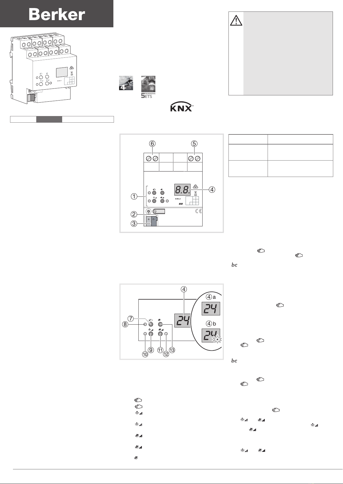
Description
1 Keyboard for manual control
2 Push Button and LED indicator for addressing
3KNX Connection
4 Display of Dali numbers
5 Connection to the network
6 Dali connection.
Control
Control Elements
4Display of the DALI numbers
- 4
a
DALI Groups
- 4
b
Individual participants
- bc :
If the display shows bc (broadcast
operation), the device is not programmed or set
to master control in the KNX configuration. All
DALI devices are then controlled jointly.
7Key : manual control
8LED on : Manual mode permanently enabled
9
Key : Turn on or adjust the light intensity
brighter
ALED on : Individual participant or DALI group
enabled : light intensity 1…100%
Z
Key : Turn o or adjust the light intensity
darker
ELED on : Individual participant or DALI group
disabled: light intensity 0%
R
Key
all
: Turn o all DALI participants.
Operating mode
Bus mode controls via push button
Short-term
manual mode
manual control using the
keyboard, automatic return to
bus mode
Permanent
manual mode
manual control exclusively via
the gateway
H- In manual mode, a bus mode is not possible.
- In the event of a failure of the bus, manual
control is possible.
- After the bus failure and a return to service, the
device operates in bus mode.
- After a power cut and a return to service, the
gateway operates in bus mode.
- Manual mode is disabled by a telegram in current
mode.
Enabling short-term manual mode
The operation of the keyboard is programmed and
is not locked.
- Press the key briefly (<1 second). 01 is
displayed on the screen, the LED remains
o or
is displayed on the screen (refer to bc). In this
mode, individual control of the participants is not
possible.
Disabling short-term manual mode
The gateway is in short-term manual mode.
- No manipulation for 5 seconds
or
- Short press on the key (<1 second) until
the gateway exits short-term manual mode. The
display turns o.
Enabling permanent manual mode
The operation of the keyboard is programmed and
is not locked.
- Press the key for at least 5 seconds.
The LED is lit, 01 is displayed on the screen,
permanent manual mode is enabled.
or
- is displayed on the screen (refer to bc)
Disabling permanent manual mode
- Press the key for at least 5 seconds.
The LED turns o and bus mode is enabled.
Controlling the DALI participants
The gateway is in permanent or short-term manual
mode.
-
Press briefly on the key ( < 1 second) until the
number of the desired DALI participant is displayed
The and LEDs display the status.
- Control the DALI participant with the key or
with the
key Short press : turns on and o
Long press : varies the light intensity brighter/
darker
The and LEDS display the status.
- In permanent manual mode, after having
been through all the available DALI participant
Product description
The DALI 75710016 KNX gateway is used to
interface DALI lighting applications with the KNX
system.
Function
Sytem information
This device is a product of the KNX system and
complies with the KNX directives. Detailed technical
knowledge obtained in KNX training courses is a
prerequisite to proper undertsanding.
The function of this device depends upon the
software. Detailed information on loadable software
and attainable functionality as well as the software
itself can be obtained from the manufacturer's
product dartabase.
Planning, installation and commissioning of the
device are carried out with the aid of KNX-certified
software. Full functionality with KNX commissioning
software version ETS3.0f onwards.
An updated version of the product database,
technical descriptions and conversion programs
and other auxiliary programs are availbale on our
internet website.
Product characteristics
• Controls up to 64 DALI products in up to 32
groups
• Individual control, group control or general control
• Setting the color temperature for luminaires with
DALI operating device Type 8 for Tunable White in
accordance with IEC 62386-209
• 16 scenes
• Eect control for dynamic sequences and sets of
colours
• Reading of the status of DALI products via KNX,
e.g. light intensity, light fitting fault, etc.
• Manual control of DALI groups
• Priority
• Feedback on the status of switching and the value
of light intensity in bus mode and manual mode
• General status feedback
• General command function
• Emergency lighting function
• Inhibition function for each group
• Separate switching and tripping delay
• Timer function with cut-o pre-warning
• Movement function : in combination with a
presence detector, reduction of the light intensity
when no movement is detected before turning o
• Online or oine commissioning of DALI products
with ETS plug-ins
• Surge protection and overload protection
• Possibility to replace an individual DALI product
without software during service
• Operating hours counter
• Delivery status : job-site mode, possibility of
ordering DALI groups using the keyboard. All
DALI products are ordered jointly.
• Signal of the global switching status of the DALI
devices, e.g. to switch o the mains voltage of
the DALI devices to avoid stanby losses.
Area
Line
Ptcp.
Nb.
all
6LE001033B
BERKER
KNX DALI TW Gateway
7571 00 16
6LE005275A
1 6LE005275A
:.?nB
75710016
- Electrical equipment must be installed
and fitted by qualified electricians only.
-
Failure to observe the instructions may
cause damage to the device and result
in fire or other hazards.
-
Danger of electric shock. Always dis-
connect before carrying out work on the
device or load. In so doing, take all the cir-
cuit breakers into account, which support
dangerous voltages to the device or load.
- This device is not suitable for dis-
connection of the mains power supply.
- The DALI control voltage is a functional
extra-low voltage (FELV). During the ins-
tallation, ensure there is a safe separa-
tion between KNX and DALI.
Da+ Da- LN
Area
Line
Ptcp.
Nb.
BERKER
KNX DALI TW Gateway
7571 00 16
6LE001033B
all
BERKER
KNX DALI TW Gateway
7571 00 16
all
DALI
numbers, the gateway exits manual mode after an
additional press.
Turning o all the DALI participants
The gateway is in permanent manual mode.
- Press the
all
key.
All DALI participants are switched o.
Locking the DALI participants or groups
individually
The gateway is in permanent manual mode.
- Press briefly on the key ( < 1 second) until the
desired DALI number is displayed.
The and LEDs display the status.
- Press the and keys simultaneously for at
least 5 seconds.
The DALI number selected flashes on the display
screen.
The DALI participant or group is locked.
- Enable bus mode (leaving permanent manual
mode).
A locked DALI participant can be controlled in
manual mode.
Unlocking the DALI participants or groups
individually
The gateway is in permanent manual mode
- Press briefly on the key (<1 second) until the
desired DALI number is displayed.
- Press the and keys simultaneously for at
least 5 seconds.
The DALI participant or group is released.
The display on the screen no longer flashes.
- Enable bus mode (leaving permanent manual
mode).
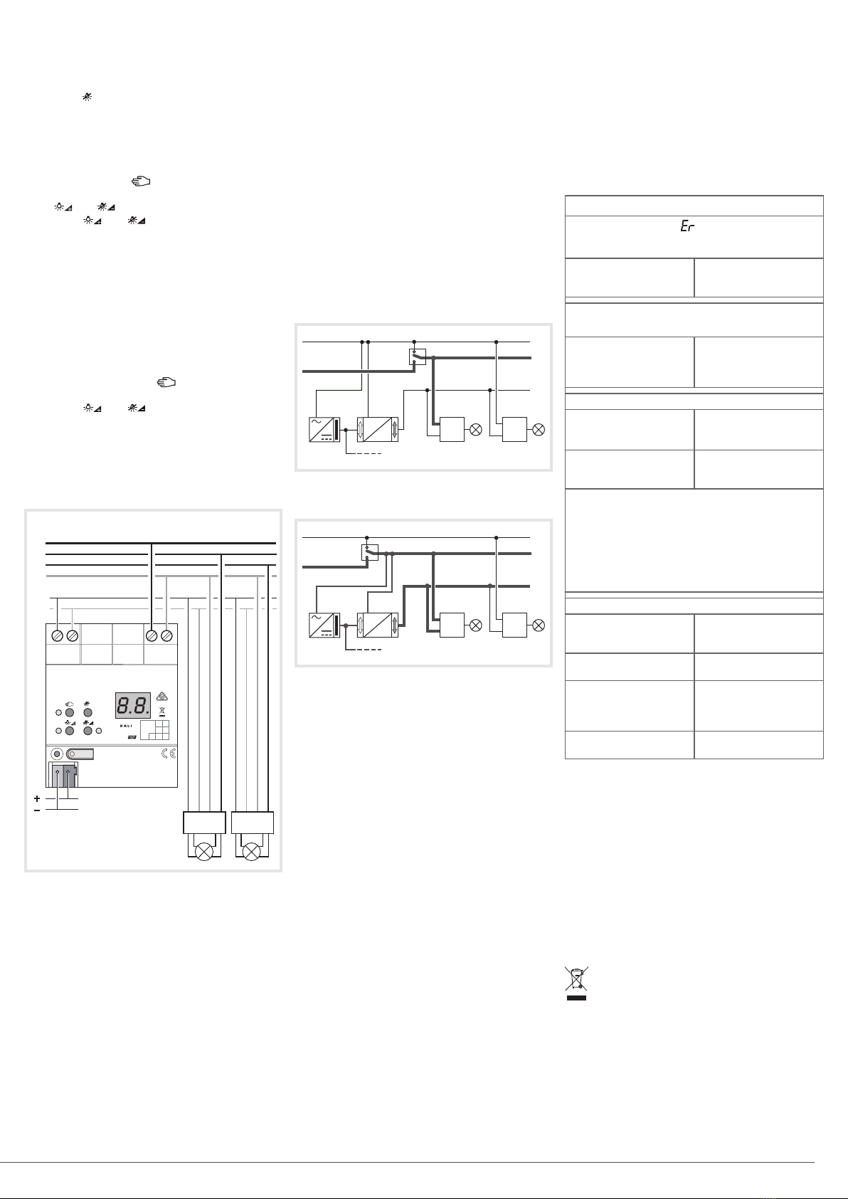
Connection
Electrical connection
Connect the device according to the diagram above.
Observe the temperature range. Ensure adequate
cooling.
When performing installation, perform the
installation in such a way that when the area is
disconnected the lines carrying both the DALI and
also the mains voltage are disconnected.
If multiple circuit breakers supply dangerous
voltages to the device or load, couple the miniature
circuit breakers or label them with a warning, to
ensure disconnection is guaranteed.
DALI devices from some manufacturers have
expanded functions and can be controlled. In the
case of upgrades of existing DALI installations,
remove all the corresponding control devices.
The DALI control voltage is a functional extra-low
voltage (FELV).
Operation of the emergency lighting
The device can be used in centrally-powered
emergency lighting systems.
G
The statutory and standard specifications vary
from country to country. In any event, the user /
technical planner should check whether the specific
specifications should be maintained.
GObserve the number of DALI devices in the
emergency luminaires used.
Emergency lighting systems with a central safety
supply are required in buildings larger than 2000 m².
Depending on the scope of functions of the system,
only the emergency luminaires are supplied by the
central safety supply (figure 1), or the KNX system and
DALI gateway are also supplied (figure 2). In the latter
case, in emergency operation, the DALI gateway can
transmit the appropriate fault messages to a central
system and other DALI gateways in the system.
Figure 1 : Emergency lighting supplied by the
central emergency power supply
Figure 2 : Emergency lighting, KNX supply and
the DALI gateway are supplied by the central
emergency power supply circuit.
*The KNX power supply must be adapted to the
voltage of the AC / DC safety source.
Commissioning
Downloading the physical address and the
application software
- Supply power to the product from the mains
- Connect the KNX bus
- Download the physical address
- Commission DALI system using commissioning
software
- Download the application software into the device.
Programming is not possible if the product is not
powered via the mains.
Technical data
Supply
Rated voltage 110 ... 240 V v
Mains frequency 50 / 60 Hz
Rated voltage DC 110 ... 240 V s
Power loss max. 3 W
Ambient conditions
Operating tempertaure -5 ... +45 °C
Storage /transport temperature -25 ... +70 °C
DALI
Rated voltage DALI 16 V (typ.)
Number of DALI subscribers max. 64
DALI transmission rate 1,2 kbit/s
DALI protocol EN 62386
Cable type Sheated cable 230 V,
e.g. NYM
DALI cable lenght
with Ø 1,5 mm² max. 300 m
with Ø 1,0 mm² max. 238 m
with Ø 0,75 mm² max. 174 m
with Ø 0,5 mm² max. 116 m
Housing
Fitting width 72 mm / 4 modules
Connection of power supply and DALI
Connection mode Screw terminal
single stranded 0,5 ... 4 mm²
Finely strande without conductor sleeve 0,5 ... 4 mm²
Finely strande with conductor sleeve 0,5 ... 2,5 mm²
KNX
KNX Medium TP
Commissionning mode S Mode
Rated voltage KNX DC 21 ... 32 V SELV
Power consumption KNX typ. 150 mW
Connection type for bus KNX Terminal
This manual is an integral part of the product
and must be kept by the end user.
What to do if…
The screen displays , the connected DALI
devices have no functions, no control is
possible
Cause : network
voltage on the DALI
bus
Solution : correct the
installation wiring fault
The screen displays bc in manual mode,
control of some light fittings is not possible.
Cause : the device has
not been programmed
or is programmed to
"Broadcast"
Solution :
program the
gateway, commission
the DALI system
Individual DALI devices have no function
Cause 1 : Load is
defective, e.g. lamp
Solution : Exchange
load
Cause 2 : DALI device
is defective
Solution : Exchange
defective device and
switch on voltage
Press buttons 7 and 13 together for at least 10
seconds.
The device detects the exchanges DALI device
and loads in the necessary data. The display
shows
LE
.
GSimultaneous exchange of multiple DALI
devices is only possible with commissioning
software and project data.
None of the DALI groups can be operated
Cause 1 : All DALI
groups disabled via bus
or manual operation
Solution : Cancel
disabling
Cause 2 : Continuous
manual mode switched on
Solution : Deactivating
permanent manual control
Cause 3 : Application
software has been
stopped, programming
LED is flashing
Solution : Perform reset:
Disconnect device from
bus, switch on again
after approx. 5 seconds
Cause 4 : Application
software missing or faulty
Solution : Check
programming and correct
6LE005275A
2
Area
Line
Ptcp.
Nb.
BERKER
KNX DALI TW Gateway
7571 00 16
6LE001033B
230 V 50/60 Hz
L1
L2
L3
N
da+
da -
da da N L da da N L
Bus 30 V
all
AC 230 V
A
C/DC 230 V
KNX
L, N
da
KNX
DALI
DALI
L, N
da
A
C 230 V
A
C/DC 230 V
KNX
*L, N
da
KNX
DALI
DALI
L, N
da
Correct Disposal of This product
(Waste Electrical & Electronic Equipment).
(Applicable in the European Union and other European
countries with separate collection systems).
This marking shown on the product or its literature indicates that
it should not be disposed with other household waste at the end
of its working life. To prevent possible harm to the environment or
human health from uncontrolled waste disposal,
please separate this from other types of waste and recycle it re-
sponsibly to promote the sustainable reuse of material resources.
Household users should contact either the retailer where they
purchased this product, or their local government oce, for details
of where and how they can take this item for environmentally safe
recycling.
Business users should contact their supplier and check the terms
and conditions of the purchase contract. This product should not
be mixed with other commercial waste for disposal.
Usable in all Europe Mand in Switzerland

Area
Line
Ptcp.
Nb.
all
6LE001033B
BERKER
KNX DALI TW Gateway
7571 00 16
Descrizione
1 Tastiera per comando manuale
2 Pulsante e spia indirizzamento
3 Collegamento KNX
4 Visualizzazione numeri DALI
5 Connessione alla rete
6 Connessione DALI
Comando
Elementi di comando
BERKER
KNX DALI TW Gateway
7571 00 16
all
4Visualizzazione numeri DALI
- 4
a
Gruppi DALI
- 4
b
Partecipanti singoli
- bc : Se sul display compare la scritta bc
(comando broadcast), il dispositivo non è
programmato o la configurazione KNX è impostata
come comando generale: in tal caso tutti i
partecipanti sono comandati contemporaneamente.
7Tasto : comando manuale
8LED acceso : Modalità manuale permanente
attivata
9
Tasto : Accendi o varia l’intensità luminosa
(più chiara)
ALED acceso : Partecipante singolo o gruppo
DALI attivato: intensità luminosa 1…100%
ZTasto
: Spegni o varia l’intensità luminosa (più
scura)
ELED acceso : Partecipante singolo o gruppo
DALI disattivato: intensità luminosa 0%
RTasto
all
: Spegni tutti i partecipanti DALI
Modalità di funzionamento
Modalità bus Comando tramite pulsanti
Modalità
manuale di
breve durata
comando manuale
direttamente con la tastiera
del gateway, ritorno
automatico alla modalità bus
Modalità
manuale
permanente
comando manuale solo
direttamente sul gateway
H- In modalità manuale, la modalità bus non è
disponibile.
- In caso di guasto del bus, è possibile il comando
manuale.
- In seguito a un riavvio successivo a un guasto del
bus, il gateway funziona in modalità bus.
- In seguito a un riavvio successivo a un’interruzione
della corrente, il gateway funziona in modalità bus.
- La modalità manuale è disattivata tramite
telegramma nella modalità corrente.
Attivazione della modalità manuale di breve durata
Il funzionamento della tastiera è programmato e
non è bloccato.
- Premere brevemente il tasto (<1 s). 01 viene
visualizzato sul display, il LED rimane spento
oviene visualizzato (V. bc sopra). In questa
modalità, non è possibile il controllo individuale
dei partecipanti.
Disattivazione della modalità manuale di breve durata
- Nessuna azione per 5 secondi
o
- Premere brevemente il tasto (<1 s) per far sì
che il gateway esca dalla modalità manuale di
breve durata. Il display si spegne.
Attivazione della modalità manuale permanente
Il funzionamento della tastiera è programmato e non
è bloccato.
- Tenere premuto il tasto per almeno 5 s. Il
LED è acceso, 01 è visualizzato sul display, la
modalità manuale permanente è attivata.
o
- è visualizzato sul display (V. bc sopra).
Disattivazione della modalità manuale permanente
- Tenere premuto il tasto per almeno 5 s.
Il LED si spegne, la modalità bus è attivata.
Comando dei partecipanti DALI
Il gateway è in modalità manuale permanente o in
modalità manuale di breve durata.
-
Premere brevemente il tasto (<1
s) fino a quando
non sarà visualizzato il numero DALI desiderato.
Lo stato è notificato dai LED e .
-Nella modalità manuale permanente, una
volta scorsi i numeri di tutti i partecipanti DALI
disponibili, premendo un’altra volta il tasto, il
gateway esce dalla modalità manuale.
Presentazione del prodotto
Il gateway KNX-DALI 75710016 permette di interfacciare
le applicazioni per l’illuminazione DALI con il sistema KNX.
Funzione
Informazione sistema
Il presente dispositivo è un prodotto del sistema
KNX ed è conforme alle direttive KNX. È richiesta
una conoscenza dettagliata acquisita seguendo i
corsi di formazione KNX.
Il funzionamento del dispositivo dipende dal software.
Le informazioni specifiche riguardanti la versione dei
software, il software stesso e il relativo funzionamento
sono indicate nel data base del fabbricante.
Per la programmazione, l’installazione e la messa in
servizio dell’apparecchiatura è necessario utilizzare
un software omologato KNX. Le funzionalità
complete sono garantite a partire dalla versione
ETS3.0f del software di messa in servizio KNX.
Le versioni correnti del data base dei prodotti, delle
descrizioni tecniche, dei programmi di conversione
e di altri programmi di assistenza sono accessibili
in qualsiasi momento sul nostro sito internet.
Caratteristiche del prodotto
• Possibilità di comandare 64 prodotti DALI max. in
32 gruppi max.
• Comando singolo, comando di gruppo e
comando generale
• Regolazione della temperatura del colore per
illuminazione con dispositivo DALI tipo 8 per una
luce bianca modulabile secondo CEI 62386-209
• 16 scenari
• Controllo eetto per sequenze dinamiche e giochi
di colore
• Lettura dello stato dei prodotti DALI via KNX, ad
es. intensità della luce, guasto lampada, ecc.
• Comando manuale dei gruppi DALI
• Forzatura
•
Feedback sullo stato della commutazione e sul
valore dell’intensità della luce in modalità bus o in
modalità manuale
• Feedback sullo stato generale
• Funzione comando generale
• Funzione luce di emergenza
• Funzione inibizione per ogni gruppo
• Ritardo separato per attivazione e disattivazione
• Funzione timer con preavviso di spegnimento
• Funzione circolazione (combinata a un rilevatore
di presenza): riduzione dell’intensità della luce se
non viene rilevato nessun movimento prima dello
spegnimento
• Messa in servizio dei prodotti DALI on-line o o-
line con plugin ETS
• Protezione contro sovraccarico, cortocircuito e
sovratensione
• Protezione contro i sovraccarichi
• Scaricatore di sovratensione
• Possibilità di sostituire un prodotto DALI singolo
senza software anche in servizio
• Contatore ore di esercizio
• Stato alla consegna: modalità cantiere, possibilità
di comandare gruppi DALI tramite tastiera. Tutti i
prodotti DALI sono comandati in gruppo.
• Informazionesullostatodicommutazionegenerale
dei partecipanti DALI, es. per l’interruzione della
tensione di rete dei partecipanti DALI così da
evitare perdite in modalità stand-by).
6LE005275A
yGateway KNX-DALI
bianco modulabile
zKNX-DALI Gateway
tunable white
Da+ Da- LN
Area
Line
Ptcp.
Nb.
BERKER
KNX DALI TW Gateway
7571 00 16
6LE001033B
all
75710016
3 6LE005275A
:.?nB DALI
- L’installazione e il montaggio delle appa-
recchiature elettriche devono essere
eettuati da un elettricista specializzato.
-
Il mancato rispetto delle indicazioni di
pericolo può causare danni al dispositivo,
incendi, ecc.
-
Rischio di scossa elettrica: prima di eet-
tuare qualsiasi intervento sul dispositivo o
sul carico, scollegare l’alimentazione. In
particolare, staccare tutti gli interruttori
dierenziali che forniscono tensioni peri-
colose al dispositivo o al carico.
- Il dispositivo non funziona se scollegato
dalla rete di alimentazione.
- La tensione di comando DALI è una bas-
sissima tensione funzionale: FELV. Durante
l’installazione, accertarsi di garantire una
separazione sicura tra KNX e DALI.

Spegnimento di tutti i partecipanti DALI
Il gateway è in modalità manuale permanente.
- Premere il tasto
all
.
Tutti i partecipanti DALI sono spenti.
Bloccare i partecipanti DALI o i gruppi
Il gateway è in modalità manuale permanente.
- Premere brevemente il tasto (<1 s) fino a
quando non sarà visualizzato il numero DALI
desiderato.
Lo stato ènotificato dai LED e.
- Premere e tenere premuti contemporaneamente
per almeno 5 secondi il tasto e il tasto .
Il numero DALI selezionato lampeggia sul display.
Il partecipante o il gruppo DALI è bloccato.
- Attivare la modalità bus (uscire dalla modalità
manuale permanente).
Un partecipante DALI bloccato può essere
comandato in modalità manuale.
Sbloccare i partecipanti DALI o i gruppi
Il gateway è in modalità manuale permanente
-Premere brevemente il tasto (<1 s) fino a quando
non sarà visualizzato il numero DALI desiderato.
- Premere e tenere premuti contemporaneamente
per almeno 5 secondi il tasto e il tasto .
Il partecipante o il gruppo DALI è sbloccato.
Il numero sul display smette di lampeggiare.
- Attivare la modalità bus (uscire dalla modalità
manuale permanente).
Collegamento
Area
Line
Ptcp.
Nb.
BERKER
KNX DALI TW Gateway
7571 00 16
6LE001033B
230 V 50/60 Hz
L1
L2
L3
N
da+
da -
da da N L da da N L
Bus 30 V
all
Collegamento elettrico
Collegare il dispositivo secondo lo schema sopra.
Rispettare il range di temperatura. Garantire un
rareddamento suciente.
I dispositivi DALI di alcuni fabbricanti hanno funzioni
estese e possono essere comandati. In caso di
aggiornamento di impianti DALI esistenti, rimuovere
tutti i dispositivi di comando corrispondenti.
La tensione di comando DALI è una bassissima
tensione funzionale (FELV).
Eseguire l’installazione facendo in modo che i cavi
di tensione DALI e i cavi della rete siano scollegati
in caso di sblocco di un dominio.
Per garantire la disconnessione, se più interruttori
dierenziali forniscono tensioni elevate al dispositivo
o al carico, accoppiare gli interruttori o apporre un
adesivo di avvertenza sugli interruttori interessati.
Funzionamento della luce di emergenza
Ilgatewaypuòessereutilizzatoinsistemid’illuminazione
di emergenza con alimentazione centralizzata.
GLe norme di legge e gli standard applicabili
variano a seconda del paese. L’utente/
pianificatore deve in ogni caso verificare che gli
obblighi di natura tecnica siano rispettati.
GRispettare il numero di partecipanti DALI nelle
luci di emergenza utilizzate.
Negli edifici di oltre 2000m², gli impianti di
illuminazione di emergenza devono avere
un’alimentazione di emergenza centralizzata. In
base al funzionamento dell’impianto, l’alimentazione
di emergenza alimenta solo le luci di emergenza
(figura 1) o l’impianto KNX e il gateway DALI (figura
2). In quest’ultimo caso, in modalità emergenza,
il gateway DALI può inviare messaggi di guasto a
una centrale o a un altro gateway DALI presente
nell’impianto.
Figura 1 : Emergenza alimentata dal circuito di
alimentazione di sicurezza centrale
AC 230 V
A
C/DC 230 V
KNX
L, N
da
KNX
DALI
DALI
L, N
da
Figura 2 : Emergenza, alimentazione KNX
e Gateway DALI alimentati dal circuito di
alimentazione di sicurezza centrale
A
C 230 V
A
C/DC 230 V
KNX
*L, N
da
KNX
DALI
DALI
L, N
da
A
C 230 V
A
C/DC 230 V
KNX
*L, N
da
KNX
DALI
DALI
L, N
da
*L’alimentazione KNX dovrà essere adattata alla
tensione della fonte di sicurezza AC/DC.
Messa in servizio
Scaricare l’indirizzo fisico e il software applicativo.
- Alimentare il prodotto tramite la rete
- Collegare il bus KNX
- Scaricare l’indirizzo fisico
- Scaricare il software applicativo all’interno del dispositivo
Se il prodotto non è alimentato tramite la rete, la
programmazione non sarà possibile.
Caratteristiche tecniche
Alimentazione
Tensione nominale 110 ... 240 V v
Frequenza rete 50 / 60 Hz
Tensione nominale DC 110 ... 240 V s
Perdite di potenza max. 3 W
Condizioni ambientali
Temperatura operativa -5 ... +45 °C
Temperatura di magazzinaggio/trasporto
-25 ... +70 °C
DALI
Tensione nominale DALI 16 V (typ.)
Numero di partecipanti DALI max. 64
Velocità di trasferimento DALI 1,2 kbit/s
Protocollo DALI EN 62386
Tipo di cavo Conduttore con guaina 230 V,
es. NYM
Lunghezza cavo DALI
per Ø 1,5 mm² max. 300 m
per Ø 1,0 mm² max. 238 m
per Ø 0,75 mm² max. 174 m
per Ø 0,5 mm² max. 116 m
Scatola
Larghezza incasso 72 mm / 4 moduli
Collegamento alimentazione e DALI
Tipo di collegamento Morsetto a vite
unifilare 0,5 ... 4 mm²
fili sottili senza puntalini 0,5 ... 4 mm²
fili sottili con puntalini 0,5 ... 2,5 mm²
KNX
KNX Medio TP
Modalità di messa in servizio Modo S
Tensione nominale KNX DC 21 ... 32 V SELV
Potenza assorbita KNX 150 mW
Tipo di collegamento bus Morsetto KNX
Questo manuale è parte integrante del
prodotto e deve essere conservato dall'utente
finale.
Che cosa fare se...
Sul display compare la scritta , i dispositivi
DALI connessi non funzionano, nessun
comando possibile
Causa : tensione di
rete bus DALI
Soluzione : correggere
l’errore di cablaggio
dell’impianto
Sul display compare la scritta bc in modalità
manuale, il comando di alcune luci non è possibile
Causa : Il gateway
non è programmato
o è programmato su
“Broadcast”
Soluzione :
programmare il
gateway, mettere in
servizio il sistema DALI
Partecipante DALI singolo non in funzi
Causa 1 : carico
difettoso (es.: una
lampada)
Soluzione : sostituire il
carico
Causa 2 : prodotto
DALI difettoso
Soluzione : sostituire
il prodotto difettoso e
metterlo in tensione
Premere e tenere premuti contemporaneamente
per almeno 10 secondi il tasto 7 e il tasto 13.
Il gateway DALI riconosce il dispositivo DALI che
è stato sostituito e carica i dati necessari. Sullo
schermo compare la scritta
LE
.
GLa sostituzione simultanea di più partecipanti
DALI è possibile solo con il software di messa
in servizio e i dati del progetto.
Nessun dei gruppi DALI può essere comandato
Causa 1 : tutti i gruppi
DALI sono bloccati
tramite bus o comando
manuale
Soluzione : eliminare il
blocco
Causa 2 : modalità
manuale permanente
attivata
Soluzione : disattivare
la modalità manuale
permanente
Causa 3 : software
applicativo non in
funzione, il LED di
programmazione
lampeggia
Soluzione : resettare:
scollegare il dispositivo
dal bus e ricollegarlo
dopo circa 5 secondi
Causa 4 : software
applicativo mancante
o errato
Soluzione : controllare
e correggere la
programmazione
II marchio riportato sul prodotto o sulla sua documentazione indica
che il prodotto non deve essere smaltito con altri rifiuti domestici al
termine del ciclo di vita. Per evitare eventuali danni all‘ambiente o
alla salute causati dall‘inopportuno smaltimento del rifiuti, si invita
l‘utente a separare questo prodotto da altri tipi di rifiuti e di riciclarlo
in maniera responsabile per favorire il riutilizzo sostenibile delle risor-
se materiali.
Gli utenti domestici sono invitati a contattare il rivenditore presso il
quale è stato acquistato il prodotto o l‘ucio locale preposto per
tutte le informazioni relative alla raccolta dierenziata e al riciclaggio
per questo tipo di prodotto.
Gli utenti aziendali sono invitati a contattare il proprio fornitore e verifi-
care i termini e le condizioni del contratto di acquisto. Questo prodotto
non deve essere smaltito unitamente ad altri rifiuti commerciali.
Usato in Tutta Europa Me in Svizzera
Corretto smaltimento del prodotto
(rifiuti elettrici ed elettronici).
(Applicabile nei paesi dell‘Unione Europea e in quelli con
sistema di raccolta dierenziata).
46LE005275A
Berker GmbH & Co. KG - Klagebach 38 - 58579 Schalksmühle/Germany - Tel. + 49 (0) 23 55/90 5-0 Fax + 49 (0) 23 55/90 5-111 - www.berker.com
Table of contents
Languages:
Other Berker Gateway manuals


 owner's manual")


