socomec DIRIS G-30 User manual

DIRIS
G-30,G-40,G-50 & G-60
Gateways
EN
USER
MANUAL
www.socomec.com
www.socomec.com/
en/diris-g

2EN
1. DOCUMENTATION.......................................................3
2. DANGER AND WARNING .................................................4
2.1. Risk of electrocution, burns or explosion ............................4
2.2. Risk of damaging the unit ........................................4
2.3. Liability .......................................................4
3. PRELIMINARY OPERATIONS ..............................................5
4. INTRODUCTION.........................................................6
4.1. DIRIS G presentation ............................................6
4.1.1. Range ...............................................6
4.1.2. Functions ............................................7
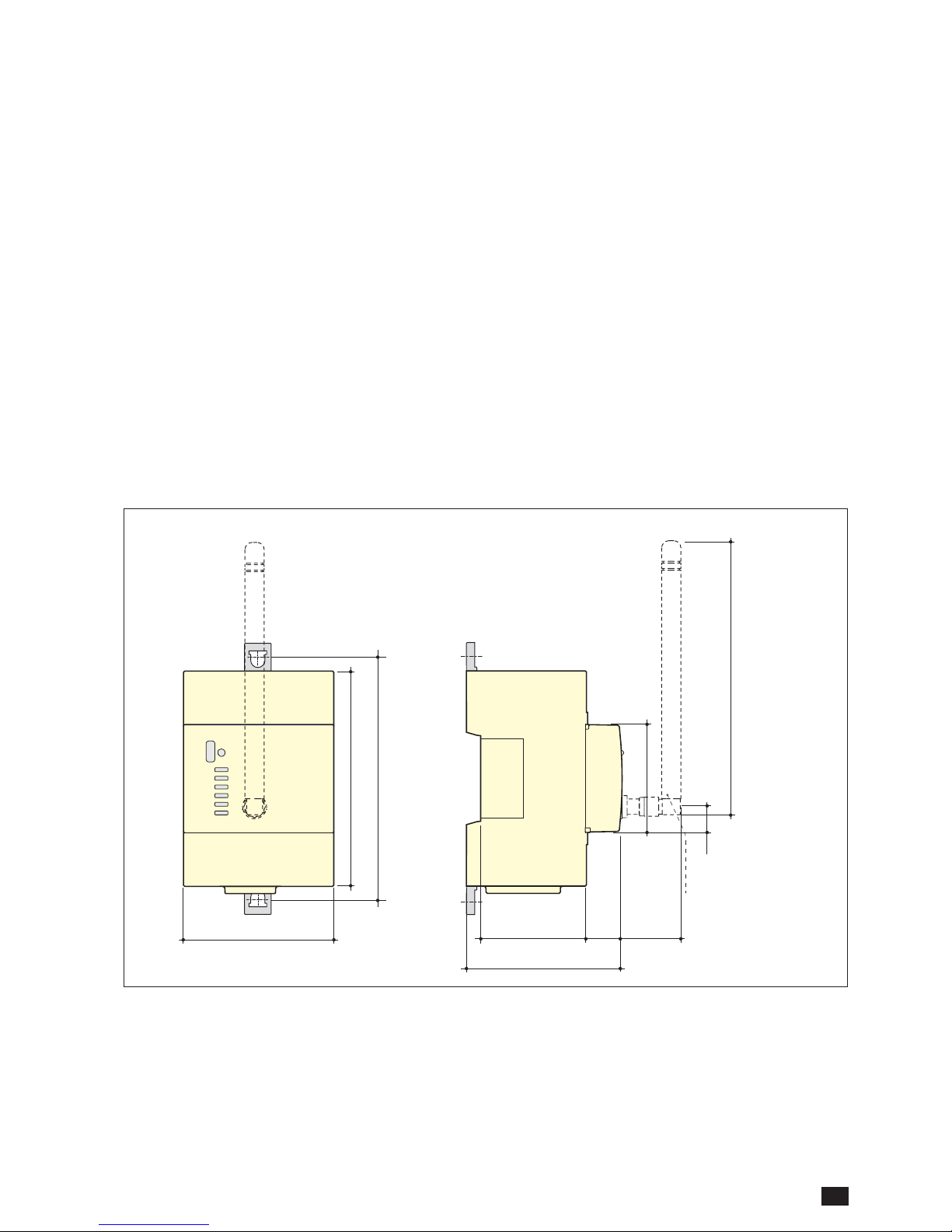
4.1.3. Dimensions ..........................................7
4.2. Optional modules presentation ....................................8
4.2.1. Range ...............................................8
4.2.2. Dimensions ...........................................8
5. ASSEMBLY.............................................................9
5.1. Recommendations and safety .....................................9
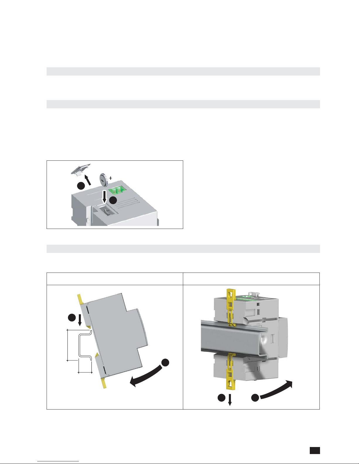
5.2. Fitting the battery ...............................................9
5.3. DIRIS G mounting ..............................................9
5.3.1. DIN-rail mounting ......................................9
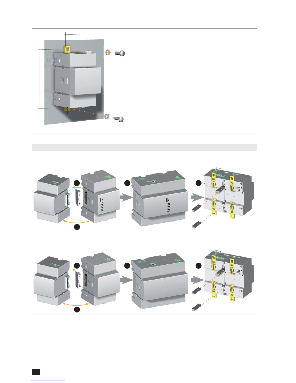
5.3.2. Plate mounting .......................................10
5.4. Optional modules mounting......................................10
.................10
..........10
6. CONNECTION .........................................................11
6.1. DIRIS G connection ............................................11
6.2. Optional modules connection ....................................13
7. STATUS AND AUTO-ADDRESSING LEDS ...................................14
7.1. Status LEDs ..................................................14
7.2. Auto-addressing...............................................15
8. COMMUNICATION......................................................16
8.1. General information ............................................16
8.2. RS485 rules ..................................................17
8.3. Radio-frequency (RF) rules. . . . . . . . . . . . . . . . . . . . . . . . . . . . . . . . . . . . . . . 18
..........................................18
............................19
8.4. Multi-gateway communication....................................19
8.5. Communication tables ..........................................19
9. CONFIGURATION ......................................................20
9.1. Configuration using Easy Config ..................................20
....................................20
9.1.2. Time setting .........................................21
10. CHARACTERISTICS ...................................................22
10.1. DIRIS G characteristics ........................................22
.............................22
...............................22
..................................22
...........................22
................................23
............................23
...........................23
.............................................24
..........................................24
10.2. DIRIS O optional modules characteristics ..........................24
EN CONTENTS

3
EN
1. DOCUMENTATION
www.socomec.com/en/diris-g

4EN
2. DANGER AND WARNING
gateways.
2.1. Risk of electrocution, burns or explosion
Failure to take these precautions could cause death or serious injuries.
2.2. Risk of damaging the unit
Failure to respect these precautions could cause damage to the unit.
2.3. Liability

5
EN
3. PRELIMINARY OPERATIONS
installation.

6EN
4. INTRODUCTION
4.1. DIRIS G presentation
*PMD: Performance Measuring and monitoring Device in accordance with IEC 61557-12.
4.1.1. Range
Gateway DIRIS G-30 DIRIS G-40 DIRIS G-50 DIRIS G-60
RF communication
Monitoring: real-time measurements and
alarms.
Monitoring: real-time measurements and
alarms.
Visualisation: measurement and consumption
datalogger.
Accessories

7
EN
4.1.2. Functions
-
-
-
-
4.1.3. Dimensions
Dimensions in/mm
2.44
62
3.54
90
3.93
100
1.77
45
4.72
120
0.59
15
1.73
44
0.59
15
2.56
65
1.42
36
DIRIS G-60

8EN
4.2. Optional modules presentation
4.2.1. Range
DIRIS O-iod DIRIS O-ioa DIRIS O-it
module
module
4.2.2. Dimensions
Dimensions in/mm
A
3.54
90
3.93
100
1.73
44
0.59
15
2.56
65
DIRIS O-iod DIRIS O-ioa DIRIS O-it
A1.77in / 45mm

9
EN
5. ASSEMBLY
5.1. Recommendations and safety
5.2. Fitting the battery
1
2
5.3. DIRIS G mounting
5.3.1. DIN-rail mounting
1
2
0.29 or 0.59
in/
mm
1.38in
35mm
1 2

10 EN
5.3.2. Plate mounting
0.19 in
5 mm
3.94 in
100 mm
0.47in/12mm
5.4. Optional modules mounting
5.4.1. Monting an optional module on the gateway
Gateway
1 3 4
module
2
Gateway
5.4.2. Mounting an optional module on an optional module
1 3 4
module
2

11
EN
6. CONNECTION
6.1. DIRIS G connection
Optional modules
USB
Power
10 mm
0.2 mm2 -> 2.5 mm2solid
2 -> 1.5 mm2
EthernetRS485
0.14 mm2 -> 1.5 mm2 solid 0.14
mm2 -> 1.5 mm2solid
1 digital input
0.14 mm2 -> 1.5 mm2 solid 0.14
mm2 -> 1.5 mm2solid
RJ45
1
digital
i
RS
48
5

12 EN
110-230 VAC
N
L
Power
IN RS485
NC
12 VDC
Input powered by the product
IN RS485
NC
10 - 30 VDC
Input with external power supply
RS485
NC
LIYCY-CY
RS485
Power supply of optional modules
110-230VAC
N
L
N
L
N
L
*
DIRIS G

13
EN
6.2. Optional modules connection
Supply
0.14 mm2 -> 1.5 mm2solid
0.14 mm2-> 1.5 mm2stranded
0.14 mm2 -> 1.5 mm2solid
0.14 mm2-> 1.5 mm2stranded
0.2 mm2 -> 2.5 mm2solid
2 -> 1.5 mm2
0.14 mm2 -> 1.5 mm2solid
2 -> 1.5 mm2
stranded
0.2
10 mm
DIRIS O-iod
module
DIRIS O-ioa
module
DIRIS O-it
3
module
0.14 mm2 -> 1.5 mm2solid
0.14 mm2-> 1.5 mm2stranded
0.14 mm2 -> 1.5 mm2solid
2 -> 1.5 mm2stranded
PT100 or PT1000
INPUT
OUTPUT
DIRIS O-iod
SUPPLY
Power supply of optional modules
DIRIS O-iod and O-ioa
INPUT
OUTPUT
DIRIS O-ioa
IN3
DIRIS O-it
IN1 IN2

14 EN
7. STATUS AND AUTO-ADDRESSING LEDS
7.1. Status LEDs
Power
Alarm
RS communication
RF communication
Pulse
ON
ALARM
-
RS COM
COM RF
ETH -
MEMORY
-

15
EN
7.2. Auto-addressing
Description of mode 1
Gateway
DIRIS G
Press
3 sec.
Press
3 sec.
Press
3 sec. 1
Press
3 sec. 6
4a
2
7 7 7
5a5b
33 3
4b

16 EN
8. COMMUNICATION
8.1. General information
Gateway DIRIS G-30 DIRIS G-40 DIRIS G-50 DIRIS G-60
RF
RF
DIRIS G default address
DIRIS
DIRIS G-40 or G-60 gateway
DIRIS G default address

17
EN
8.2. RS485 rules
DIRIS G gateway
recommended.

18 EN
8.3. Radio-frequency (RF) rules
Gateway
RS485-RF / Ethernet
RF
RF
RF
8.3.1.
Channel no. Frequency (MHz) Permitted occupancy rate Maximum number of
DIRIS B-30 connected
420 16
436 16
452 16
3
3
504 3
32
539 32

19
EN
8.3.2. EC Declaration of Conformity
www.socomec.com/en/diris-g
8.4. Multi-gateway communication
Master gateway
RS485-RF / Ethernet
Slave gateway
RS485-RF / Ethernet
8.5. Communication tables
www.socomec.com/en/diris-g

20 EN
9. CONFIGURATION
9.1.
9.1.1. Connection modes
Gateway
Gateway
Other manuals for DIRIS G-30
2
This manual suits for next models
3
Table of contents
Other socomec Gateway manuals
Popular Gateway manuals by other brands

BAB TECHNOLOGIE
BAB TECHNOLOGIE KNXEASY Documentation

ICP DAS USA
ICP DAS USA PFN-2000 Series HOW TO UPDATE FIRMWARE

Lucent Technologies
Lucent Technologies PacketStar PSAX 1000 user guide

Yeastar Technology
Yeastar Technology TA1610 user manual

IQRF
IQRF GW-WIFI-01 user guide

Grandstream Networks
Grandstream Networks HandyTone-701 user manual