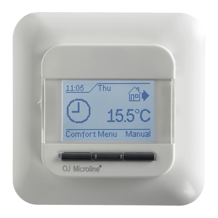
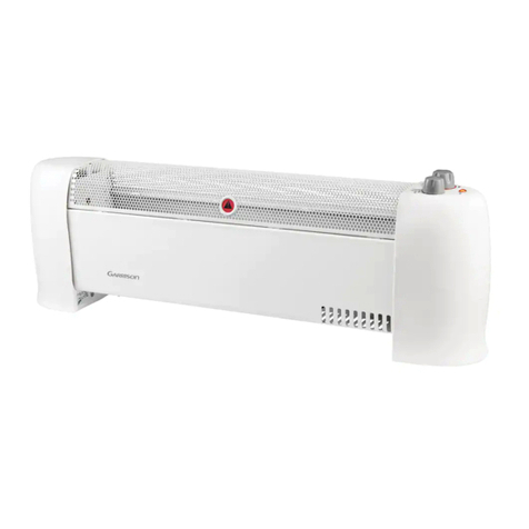
Berker 2044 Series User manual

Thermostat NO contact with centre plate, time-controlled
Thermostat NO contact with centre plate, time-controlled
Order no.: 2044 xx
Operation and installation instructions
1 Safety instructions
Electrical equipment must only be installed and assembled by qualified electricians.
Always follow the relevant accident prevention regulations.
The device is compliant with the guidelines of the EN 60730 and works according to the
mode of operation 1C.
Failure to comply with these instructions may result in damage to the device, fire or other
hazards.
These operating instructions are an integral component of the product, and must be
retained by the end user.
2 Design and layout of the device
(1)
(2)
(3)
(4)
(5)
(6)
(7)
Figure 1: Device overview
(1) Display
(2) Operating keys
(3) Operating unit
(4) Plug-in contacts for insertion
(5) Frame (not included in delivery)
(6) Socket for plug-in contacts
(7) Insert
97-09920-000
Page 1/15 10/2011

Thermostat NO contact with centre plate, time-controlled
3 Function
The time-controlled thermostat allows the room temperature to be controlled in automatic mode
depending on the time and weekday (program) so that the heating requirements can be
adjusted according to individual lifestyles. The automatically controlled temperature can also be
adjusted manually as required.
The device is controlled by the measured value of the internal sensor. When the temperature
falls below the programmed value, the room is heated. in addition, an external sensor can be
connected for measuring the floor/room temperature.
The thermostat process can be adjusted according to the heating type:
–Room thermostat
The heater is switched on if the room temperature falls below the preset default value.
–Floor thermostat
The floor temperature is controlled. The heating is switched on if the room temperature
(measured by the external thermostat) falls below the default value.
–Room thermostat with limiter
The room temperature is controlled, the floor temperature (measured by the external
temperature sensor) is limited independent of this. The heater is switched on when the
room temperature falls below the preset default value.
4 Operation
Operator control concept
OK
°C
4
(8) (9) (10) (11)
(12)
(13)
(14)
(15)
(16)
Figure 2: Overview of the operating elements and basic display
(8) Push-button Menu/s
(9) Push-button –
(10) Push-button +
(11) Push-button Info/OK
(12) Current time/display of help texts
(13) Display of heating mode
(14) Display of day of the week
(15) Display of room temperature
(16) Display of function/settings
97-09920-000
Page 2/15 10/2011

Thermostat NO contact with centre plate, time-controlled
Operating thermostat
You can navigate through the menu using the four push-buttons below the display. In the menu
the functions can be set and activated and settings can be adjusted.
The operation can also be carried out when the operating unit is removed.
If no push-button is actuated for longer than 3 minutes, the device returns automatically to
the previous function and basic display.
In the basic display, press the Info/OK (11) push-button.
Information on the current operating mode/function is displayed as scrolled text. The device
returns to the basic display by re-pressing Info/OK.
Press Menu/s(8) push-button.
The basic display disappears. MENU appears briefly in the function display (16). A help
text on the current selection is shown at the bottom of the display (12) as scrolled text. The
menu can be selected.
The device returns to the last display/setting in the menus by pressing Menu/s. The device
returns again to the basic display by pressing Menu/srepeatedly.
Press +/– (9/10) push-button.
Operating modes/functions and settings menus are changed. A description appears below
in the display.
Press Info/OK (11) push-button.
Function selection:
The current function selection is confirmed. Carry out any necessary settings using the +/–
(9/10) push-button if required and press Info/OK (11) to confirm.
Settings:
The selection of the settings menus is confirmed. Carry out further settings with the +/–
(9/10) push-button and press Info/OK (11) to confirm.
Once all settings have been completed, the device returns to the basic display. The
selected function appears in the display (16).
In the settings menus identifiers of the function also appear as scrolled text in the display
(15) in addition to the adjustable function.
Adjusting setpoint temperature manually
The setpoint temperature can always be adjusted in the AUTO and MAN operating modes.
The device is in the basic display.
Press +/– (9/10) push-button.
The current setpoint temperature flashes.
Keep pressing the +/– push-button repeatedly until the desired temperature is displayed.
Press the OK (11) push-button to save the displayed temperature.
The device returns to the basic display.
The readout AUTO– indicates that the manually adjusted setpoint temperature deviates
from the temperature stored in the time temperature program. The temperature is
controlled according to the changed setpoint temperature until the next event.
Switch off controller
The device is in the basic display.
Keep the Menu/spush-button (8) pressed for 10 s.
The display first returns to the menu. The device returns to the basic display after 10 s. The
function display (16) indicates OFF.
The controller is switched on again by selecting an operating mode/function.
97-09920-000
Page 3/15 10/2011

Thermostat NO contact with centre plate, time-controlled
Selecting and changing programs
The control provides three preset time temperature programs
Program 1
6:00 h 8:00 h 10:00 h 12:00 h 14:00 h 16:00 h 18:00 h 20:00 h 22:00 h
Mon – Fri
Sat – Sun
Figure 3: Time temperature diagram (day profile) for program 1
Program with six events and temperature setback to 18 °C in the morning and afternoon of
working days (absence). At the weekend temperature setback in the morning and night setback.
Mon – Fri Sat – Sun
Event ðC ðC
1 6:00 21.0 7:00 21.0
2 8:30 18.0 10:00 18.0
3 12:00 21.0 12:00 21.0
4 14:00 18.0 14:00 21.0
5 17:00 21.0 17:00 21.0
6 22:00 15.0 Sat: 23:00
Sun: 22:00
15.0
Program 2
6:00 h 8:00 h 10:00 h 12:00 h 14:00 h 16:00 h 18:00 h 20:00 h 22:00 h
Mon – Fri
Sat – Sun
Figure 4: Time temperature diagram (day profile) for program 2
On weekdays like program 1. At the weekend an event for comfort temperature during the
whole day and night setback.
Mon – Fri Sat – Sun
Event ðC ðC
1 6:00 21.0 7:00 21.0
2 8:30 18.0
3 12:00 21.0
4 14:00 18.0
5 17:00 21.0
6 22:00 15.0 Sat: 23:00
Sun: 22:00
15.0
97-09920-000
Page 4/15 10/2011

Thermostat NO contact with centre plate, time-controlled
Program 3
6:00 h 8:00 h 10:00 h 12:00 h 14:00 h 16:00 h 18:00 h 20:00 h 22:00 h
Mon – Fri
Sat – Sun
Figure 5: Time temperature diagram (day profile) for program 3
Program with four events and temperature setback to 18 °C during the day (absence). At the
weekend temperature setback in the morning and night setback.
Mon – Fri Sat – Sun
Event ðC ðC
1 6:00 21.0 7:00 21.0
2 8:30 18.0 10:00 18.0
3 17:00 21.0 17:00 21.0
4 22:00 15.0 Sat: 23:00
Sun: 22:00
15.0
Selecting program (G 1)
In the standard delivery, program 1 is active.
The device is in the basic display.
Press Menu/s(8) push-button.
A help text is shown at the bottom of the display (12).
Select the settings menu USER SETTING with push-button +/– (9/10) and press OK to
confirm (see operating thermostat).
G 1 - PROGRAM SELECT ONE is displayed.
Press OK.
The number of the active program flashes.
Using +/– select the desired program (1 ... 3) and press OK to confirm.
G 1 and the scrolled text PROGRAM SELECT is displayed once again. The selected
program is active.
Adjust program (G 2)
The preset programs can be adjusted to personal requirements. A maximum of 9 events per
day are possible.
Adjustments affect the selected program. Adjustments are not saved if the program is
changed. The adjustments of the standard program must be carried out once again.
The program returns to the previous setting level by pressing the Menu/spush-button.
Further adjustments can be carried out there if required.
The device is in the basic display.
Press Menu/s(8) push-button.
A help text is shown at the bottom of the display (12).
97-09920-000
Page 5/15 10/2011

Thermostat NO contact with centre plate, time-controlled
Select the settings menu USER SETTING with push-button +/– (9/10) and press OK to
confirm (see operating thermostat).
G 1 - PROGRAM SELECT ONE is displayed.
Keep pressing the +/– push-button repeatedly until G2 - EVENT SETTING is displayed.
Press OK.
DAY is displayed, the weekday display (14) flashes.
Besides individual weekdays, events can also be set for day blocks 1-5, 6-7, 1-7. 1
corresponds to Monday ... 7 Sunday.
Select the desired day using the +/– push-button and press OK to confirm.
The temperature display (15) flashes for the first switching interval of the day.
Set the desired temperature using the +/– push-button and press OK to confirm.
The start time of the switching interval flashes.
Set the desired start time using the +/– push-button and press OK to confirm.
The end time of the switching interval flashes.
Set the end time using the +/– push-button and press OK to confirm.
The temperature for the next switching interval flashes.
9 events per day are possible. The number of the switching interval is displayed before the
events. The respective end time in the display is saved as the start time of the next interval.
If ->>> flashes in the display, then the following event is on the next weekday. If OK is
pressed, the display for the start time changes to the start time of next weekday. If +/– is
pressed, a further switching interval is created. If all 9 events of a day have been used, the
program moves automatically to the next weekday.
Further temperatures and events can be set similarly if necessary.
Press Menu/srepeatedly to exit the menu item G2 - EVENT SETTING.
The settings are saved.
Selecting function
The device is in the basic display.
Press Menu/s(8) push-button.
A help text is shown at the bottom of the display (12).
Keep pressing the +/– (9/10) push-button repeatedly until the desired menu item (Function
or Settings menu) is displayed.
Press OK (11) push-button.
The function is activated in the AUTO and MAN operating modes.
In the remaining operating modes/functions, the device returns to further settings (see
Table 1: Overview of the functions and operation).
Function Description
Operation
Display
AUTO Control the room temperature according to time and temperature
parameters of the selected program
Activation: OK
Adjust the temperature until the next event: +/– in the basic display
Display of function (16): AUTO
97-09920-000
Page 6/15 10/2011

Thermostat NO contact with centre plate, time-controlled
MAN Time-independent control of the room temperature according to the value
set here
Activation: OK
Set temperature: +/– in the basic display
Display of function (16): MAN
TIMER Specifying a room temperature for a set number of hours
Set hours: +/–
Activation: OK
Display of function (16): TIMER
Display of time (12): xh (x = number of remaining hours)
HOLIDAY Specifying a room temperature for a set time period with start and end date
of the holiday
The AUTO function is active until the start of the holiday. Alternatively, the
AUTO, MAN, TIMER, AT HOME functions can be set. HOLIDAY starts
when the start date is reached.
Set Year, Month, Day, Temperature: +/–, confirm each setting by
pressing OK.
Activation by confirming the temperature setting: OK
Display of function (16): U.
Display of time (12): End date of the holiday in the format DD-MM-YY
AT HOME Temperature control independent of the weekday according to time and
temperature parameters of the set program (day profile).
The presettings of the program correspond to the current day program of
Monday.
Set temperature and events: +/–, confirm each setting by pressing OK
Activation with confirmation of the last event
Display of function (16): HOME
USER SETTING Invoke a settings menu for user settings (see User settings)
Invoke: OK
Display of room temperature (15) shows the menu identification - beginning
with G.
Scrolled text at the bottom of the display with information about the current
settings menu
INSTALLER
SETTINGS
Invoking a settings menu for the electrician
Invoke: OK (see Information for Electricians – Commissioning)
Display of room temperature (15) shows the menu identification - beginning
with H.
Scrolled text at the bottom of the display with information on the current
settings menu
Table 1: Overview of the functions and operation
Setting default values
Default settings need to be set for some functions e.g. times/temperatures. The value to be set
then flashes in the display.
Value flashes.
Set the default value using the +/– push-button and press OK to confirm.
The new value is saved, the next value to be set flashes.
97-09920-000
Page 7/15 10/2011

Thermostat NO contact with centre plate, time-controlled
97-09920-000
Page 8/15 10/2011
When all values have been set, the display returns again to the basic display. The function
is executed.
User settings (Table 2)
The behaviour of the controller is set in the settings menu User settings. The settings menu is
accessed via the menu (see Select function). A scrolled text at the bottom of the display makes
the selection easier.
Setting Description
Operation
G1
SELECT
PROGRAM
Selection of the preset time temperature programs (see Select program)
Factory setting: 1- Program 1
Select program 1, 2or 3: +/–
G2
EVENT SETTING
Adjusting a preset time temperature program
Set weekday, temperature, event: +/–, press OK to confirm (see
Adjusting program)
G3
CLOCK SETTING
Setting the date and time
Set YEAR,MONTH,DAY,HOUR,MINUTE: +/–, press OK to confirm
G4
OFF HEATING
PERMANENT
Switch off the controller, no temperature, frost protection is active, if set
by the electrician.
Select: YES/NO - heating off/on : +/–, press OK to confirm
Display of function (16): OFF
Switch on controller again: Select any function via the menu or keep
Menu/spressed down for 10 s
G5
SUMMER/WINTER
TIME CHANGE
Select whether or not the summer/winter time change should be carried
out automatically.
Factory setting: YES - Switchover on
Select: YES/NO: +/–, press OK to confirm
G6
KEY LOCK
Protection of the controller against unauthorized operation
If the key lock is active, no operation is possible
Select: YES (key lock)/NO: +/–, press OK to confirm
Cancel key lock again:
Press any push-button, when CODE is displayed set 93 using +/– and
press OK to confirm
G7
TEMP LIMIT
MIN/MAX TEMP
Set parameter of the lower and upper temperature for the controller
Factory setting:
LOWER TEMP LIMIT = 5 °C, UPPER TEMP LIMIT = 30 °C
Set temperatures: +/–, press OK to confirm
G8
COST/HR
OF ENERGY
Enter the estimated energy costs per hour for the room being controlled.
The calculated consumption is displayed under G9.
If the energy costs counter should be used as operating hours
counter, set value COSTS/h to 100.
Factory setting: 10
Set COSTS/h: +/–, press OK to confirm

Thermostat NO contact with centre plate, time-controlled
G9
ENERGY-
CONSUMTION TO
DATE
Display of the approximate calculated energy consumption/operating
hours for 2 DAYS – WEEK – 30 DAYS – YEAR.
The current day until the display time is taken into account.
Calculation: Duty cycle of the heating x COSTS/h
Select time period for calculating the energy consumption: +/–
Return to the menu: OK
Resetting using INSTALLER SETTINGS H9
G10
SET TEMP TO
READ
Setting whether the setpoint temperature should be displayed in the
basic display instead of the current room temperature
Work setting: NO – room temperature display
Select: YES/NO: +/–, press OK to confirm
G11
ADJUST TEMP
Determining the correction value by which the measured temperature
should be corrected for display and controller
Sensible adjustments: e.g. alignment with calibrated thermometers,
compensation of installation heights and installation locations that
are not optimum
Factory setting: 0.0 - no correction
Adjust correction value: +/–, press OK to confirm
G12
NUMBER FOR
FLOOR
TEMPERATURE
Only when using as floor temperature controller!
Activating the display of the floor temperature as information number
The display °C is hidden
Factory setting: NO (normal temperature display)
Select: YES/NO: +/–, press OK to confirm
G13
BACKLIGHT
Adjusting the display lighting:
SHORT = on for a short time after pressing push-button,
OFF = permanently off
Factory setting: SHORT
Set lighting behaviour: +/–, press OK to confirm
G14
LANGUAGE
Selection of the language for the display text in the display:
DEUTSCH, ENGLISH, NEDERLANDS, FRANCAIS
Select language: +/–, press OK to confirm
G15
INFO
Display of the controller type and controller version
Return to menu: OK
G16
RESET USER
SETTINGS ONLY
Resetting the user settings to factory settings
The counter ENERGY-CONSUMTION TO DATE is not reset. The
settings are reset via menu H9.
Select: YES (Reset)/NO: +/–, press OK to confirm
Table 2: Overview of the user settings and their selection
Invoking settings menu
The display shows G1 - PROGRAM SELECT ONE.
Select the desired menu using +/–.
A menu identification and help text are shown at the bottom of the display (12).
Press OK.
The first adjustable value flashes in the display.
Adjust the desired value using +/–.
Press OK.
97-09920-000
Page 9/15 10/2011

Thermostat NO contact with centre plate, time-controlled
The next adjustable value flashes in the display.
Once all values have been adjusted, the display returns to the subordinate level.
5 Information for electricians
5.1 Assembly and electrical connection
DANGER!
Touching live parts can result in an electric shock.
An electric shock can lead to death.
Disconnect connecting cables before working on the device and cover all live
parts in the area!
Installation location
To enable optimum room temperature control using the internal sensor, the installation location
selected should
–allow free air circulation
–not be located behind curtains, cupboards, shelves, etc.
–not be exposed to direct sun light
–be free of draughts
–not be on external walls
–be approx. 1.5 m above the floor
Connecting and mounting the device
Remove operating unit from the insert.
Strip a max of 8 mm from connecting cables.
Sensor
LNN
230V~, 50Hz
L
N
Last /
Load
(17)
(18)
Figure 6: Connection diagram
Connect controller according to connection diagram (Figure 6).
Connect an external temperature sensor if necessary (see connecting temperature sensor).
97-09920-000
Page 10/15 10/2011

Thermostat NO contact with centre plate, time-controlled
Figure 7: Mounting
Align insert (7) in the connector socket and fix it into position with fastening screws (20).
Mount the insert in such a way that the plastic tongue (19) acts as insulation for the
fastening screw. (Figure 7)
Mount the design frame (5) and fix it into position by attaching the operating unit (3).
Connecting external temperature sensor
An external temperature sensor is required for the thermostat process of the floor thermostat
and thermostat with limiter. It is advisable to lay the temperature sensor in a protective pipe so
that it can be replaced later.
The wire of the temperature sensor supplies mains voltage and can be extended to 50 m
using suitable wires.
To avoid signal disturbances, do not lay the wire of the temperature sensor together with
mains cables.
Strip a maximum of 8 mm from the temperature sensor wire.
Connect temperature sensor according to connection diagram (Figure 6, 18).
Figure 8: Terminal for connecting the temperature sensor
When using flexible wire, insert and remove the wire release button (21) with an
appropriate tool.
5.2 Commissioning
CAUTION!
Malfunction of the heating system with incorrect controller settings.
The heating system could get damaged.
Only allow settings of the heating system to be carried out by a skilled specialist.
(
21
)
(
20
)
(
19
)
97-09920-000
Page 11/15 10/2011

Thermostat NO contact with centre plate, time-controlled
Setting the heating type
When commissioning the controller, the heating type must be set.
The device is in the basic display.
Press Menu/s(8) push-button.
A help text is shown at the bottom of the display.
Keep pressing the +/– push-button repeatedly until INSTALLER SETTINGS is displayed.
Press OK.
CODE is displayed and the code number 0flashes.
Select code number using 7+/– and press OK to confirm.
H1 and the scrolled text of APPLICATION is displayed.
Press OK.
Set the desired temperature using +/– and press OK to confirm.
ROOM is preset. When changing the heating type, all user and installer settings are reset
to the factory settings.
Overview and selection of the settings
The settings menu is invoked (see Setting heating type). If H1 and the scrolled text of
APPLICATION is displayed, you can toggle between the possible settings menus using +/–
(see Table 3).
Setting Description
Operation
H1
APPLICATION
Selecting between the thermostat processes according to heating type:
- ROOM = Room thermostat
- FLOOR = Floor thermostat
- LIMITER = Room thermostat with limiter
Factory settings: ROOM
When used as a room thermostat, it is also possible to set whether an
external temperature sensor (EXTERNAL SENSOR = YES) is
connected.
Selection of the heating type: +/–, press OK to confirm
H2
CONTROL MODE
Selection of the control type:
–PWM (Pulse width modulation) with adjustment option for cycle
time. Select short cycle time for fast heating systems and long
cycle time for slow heating systems.
Factory setting of cycle time: 10 min
The minimum switch on/off time is 10 % of the cycle time.
–ON/OFF (on-off control) with the setting option of hysteresis and
minimum switch on/off time of the relay
Factory setting hysteresis: OFF
Factory setting minimum switch on/off time: 10 min
If no hysteresis is set, the relay switches with the set minimum
switch on/off time even in the case of very small temperature
differences.
Selection of controller, cycle time, hysteresis, switch on/off time: +/–,
press OK to confirm
97-09920-000
Page 12/15 10/2011

Thermostat NO contact with centre plate, time-controlled
H3
MIN/MAX
FLOORTEMP
Only when using as room thermostat with limiter.
Setting the minimum and maximum floor temperature for the limit:
–LOWER LIMIT OF FLOOR TEMPERATURE: The floor does not
become colder than the temperature set here.
Factory settings: OFF (no limit)
–UPPER LIMIT OF FLOOR TEMPERATURE:The floor does not
become colder than the temperature set here.
Factory setting: 35 °C
Set temperatures: +/–, press OK to confirm
The lower temperature limit < 10 °C or the upper temperature limit
> 40 °C must be set using +/– in order to deactivate the upper or
lower limit with OFF. OFF is displayed.
H4
HEATING OR
COOLING
Switchover of the controller to cooling mode/heating mode
Cooling mode only when using as room thermostat and H2 -
CONTROL MODE =ON/OFF
In cooling mode:
–Using the events and temperature of the heating mode
–H6 FROST PROTECTION =OFF
–H7 OPTIMUM START = NO
Selection of cooling/heating: +/–, press OK to confirm
H5
VALVE
PROTECTION
Protection of the valve against sticking after a longer absence of
control
The valve is opened daily at 10:00 for the time set here in minutes.
Factory setting: 3 min
Set opening time: +/–, press OK to confirm
H6
FROST
PROTECTION
Setting the frost protection mode and temperature
When frost protection is activated, the heating is activated if the
temperature falls below the set frost protection temperature.
Factory setting: 5 °C
Frost protection mode only possible when controller is switched
off.
Set temperature: +/–, press OK to confirm.
To deactivate the frost protection with OFF, set the temperature
< 5 °C by pressing the push-button –. OFF is displayed.
H7
OPTIMUM START
This setting causes the set setpoint temperature to be reached already
at the start time. AUTO_ is displayed in the required pre-heating time.
Factory setting: YES
Set YES (OPTIMUM START)/NO: +/–, press OK to confirm
H8
VALVES NORMALLY
OPEN
Switchover of the relay switching behaviour opened for using actuators
currentless
Factory setting: NO (deactivated)
Select: YES (activated)/NO: +/–, press OK to confirm
H9
ENERGY COUNTER
RESET
Resetting the energy costs counter set under G8/G9 to 0
Select YES (reset): +/–, press OK to confirm
H10
DISPLAY FLOOR
TEMPERATURE
Only when using as room thermostat with limiter.
Display of the current floor temperature for service purposes
---
97-09920-000
Page 13/15 10/2011

Thermostat NO contact with centre plate, time-controlled
H11
RESET ALL
Resetting all installer and user settings carried out in the settings menu
to the factory settings
Select YES (reset): +/–, press OK to confirm
Table 3: Overview of the installer settings and their selection
Displaying device errors
Errors in the hardware configuration can be shown via the display. In this case, ERR and an
additional error type are displayed as scrolled text.
Error type Description
Measures for removal
ERR
CONFIGURATION
Operating unit and insert do not match
–Only use related components
–Switch off voltage and switch on again
ERR
COMMUNICATION
Communication between operating unit and insert interrupted
–Remove operating unit and attach once again
–Switch off voltage and switch on again
ERR
EXT SENSOR
Failure/short circuit of the external temperature sensor
–Replace temperature sensor
Display range exceeded/fallen short of
---
6 Appendix
6.1 Specifications
Operating voltage AC 230 V~
Rated frequency 50 Hz
Output relay NO contact, potential-linked
Switching current 10 mA ... 10 (4)A, 230 V~
Power consumption approx. 1.2 W
Protection class IP30
Protection Class II
Operating temperature 0 ... 40 °C (without condensation)
Storage temperature -20 ... 70 °C (without condensation)
Temperature-adjustment range in 0.5 °C increments
Room thermostat (with limiter) 5 ... 30 °C
Floor thermostat 10 ... 40 °C
Temperature display in 0.1 °C increments
Output signal Pulse width modulation (PWM)
or on-off control (On/Off)
PWM cycle time adjustable
Hysteresis adjustable (with on-off control)
Minimum event 10 min
Time deviation < 4 min per year
Power reserve by means of lithium battery approx. 10 years
97-09920-000
Page 14/15 10/2011

Thermostat NO contact with centre plate, time-controlled
97-09920-000
Page 15/15 10/2011
6.2 Resistance/temperature table for remote sensor
Temperature [°C] 10 20 25 30 40 50
Resistor [kΩ] 66.8 41.3 33 26.3 17.0 11.3
6.3 Troubleshooting
It becomes warm too late
Cause 1: Programmed events or time do not match.
Adjust programming.
Cause 2: A summer/wintertime changeover has taken place in the meantime (G5).
Adjust time.
Cause 3: Optimum Start H7 is deactivated or has not run long enough yet (a few days) to
determine the optimum pre-heating time.
Select Optimum Start and give the controller time to adjust itself to the conditions of the
controlling environment.
It is not possible to enter any data
Cause 1: Key lock G6 is active.
Cancel key lock.
The desired temperature cannot be set
Cause 1: Temperature limit G7 prevents the desired setting.
Reset temperature limit.
Temperature display does not change
Cause 1: Display of the set temperature G10 is activated.
Activate display of the room temperature.
6.4 Warranty
We reserve the right to make technical and formal changes to the product in the interest of
technical progress.
Our products are under guarantee within the scope of the statutory provisions.
If you have a warranty claim, please contact the point of sale or ship the device postage free
with a description of the fault to the appropriate regional representative.
Berker GmbH & Co. KG
Klagebach 38
58579 Schalksmühle/Germany
Phone: + 49 (0) 23 55/90 5-0
Fax: + 49 (0) 23 55/90 5-111
www.berker.com
This manual suits for next models
1
Table of contents
Other Berker Thermostat manuals
Popular Thermostat manuals by other brands
Honeywell
Honeywell TL8130A1005 owner's guide
Doepke
Doepke Dupline DRT 1 operating instructions
Bio Green
Bio Green Thermo 2 Installation and operating instruction
Worcester
Worcester Greenstar Comfort I RF Installation and operating instructions

HAI
HAI RC-100 installation instructions

Salus
Salus ERT30 instruction manual
Emerson
Emerson 1F75C-11PR user manual
OJ Electronics
OJ Electronics WLM2 installation manual
Honeywell
Honeywell CHRONOTERM IV T8624D installation instructions
Aube Technologies
Aube Technologies TH147-P Installation and user guide
Cornelius
Cornelius 629088480 installation instructions

NOVASTAT
NOVASTAT EL INWALL RT-UW manual
