manuals.online logo
Brands
  1. Home
  2. •
  3. Brands
  4. •
  5. POLA
  6. •
  7. Thermostat
  8. •
  9. POLA HP43 User manual

POLA HP43 User manual

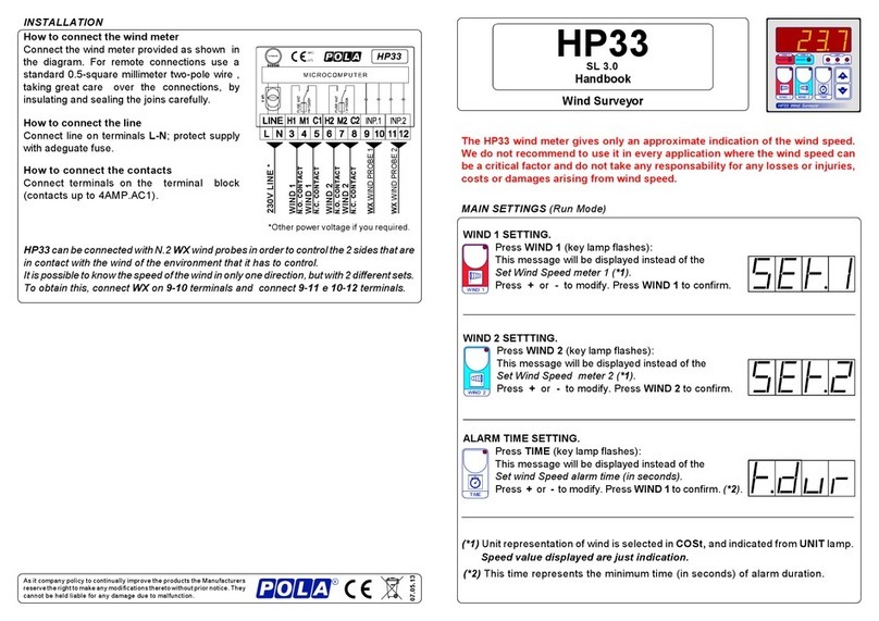
MAIN SETTING (Run mode)
The light situated at the bottom of the display shows the state of the controller:
STATE INDICATION LAMPS
Lamp 1-2-3-4 flashing if zone not viewing is in alarm condition.
Other alarm contacts available only with HPAL slot option.
Quad-zone alarm
HP43
SL 2.1
Handbook
AUTO/OFF SELECTION.
Press SCAN severals time to move to Zone required (Zone
light comes on).
Press MODE (key lamp flashes):
This message refering to the set condition, will be
displayed (Auto= Automatic, -oF- = disabled).
Press +or -to modify, press MODE to excape.
EXAMPLE ZONE 1
EXAMPLE ZONE 1
SET MODE.
Press SCAN several times to move to the zone to
program(Zonelightcomeson).
Press SET (key lamp flashes):
This message will be displayed instead of the
°Set MinimumAlarm Temperaturevalue.
Press +or -to modify, press SET to confirm.
At this point this message will be diplayed instead of the
° Set Maximum Temperature value .
Press +or -to modify, press SET to excape.
EXAMPLE VIEWING °C TEMPERAT.
INPUT VIEW.
Press SCAN several times to move to the Zone to
display (Zone light comes on).
The display will show the value measured by the
temperaturesensorof the selectedarea.
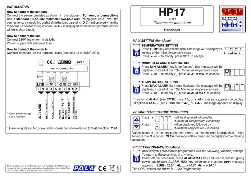
How to connect the line
Connect line on terminals L-N; protect supply with
adeguate fuse
INSTALLATION
How to connect the contacts
Connectterminalsonthe terminal block(contactsup
to 4AMP.AC1)
*Other power voltage if you required.
Or Alarm output available
onli with HPAL optional slot.
Howto connectthe sensors
Connect the provided sensor as shown in the
diagram. For remote connections use astandard
0.5-square millimeter two-pole wire , taking great
care over the connections, byinsulatingandsealing
the joins carefully. -O.C.- is displayed when the
temperaturesensorwiringisopen, -S.C.- isdisplayed
when the temperature sensor wiring is short circuit.
ZONE 2 ALARM
ZONE 1 ALARM
230V LINE *
HP43
ZONE 3 ALARM
ZONE 1
TEMP. PROBE
ZONE 2
TEMP. PROBE
ZONE 3
TEMP. PROBE
ZONE 4
TEMP. PROBE
ZONE 4 ALARM
As it company policy to continually improve the products the Manufacturers
reservetherighttomakeanymodificationsthereto without prior notice. They
cannotbeheldliableforanydamageduetomalfunction.
02.01.13
.pmaL etatS yaleR°N stctatnoC
OTUA citamotuAnodetcelesenoZ
FFO )ffo(delbasiDdetcelesenoZ
1detceles1enoZ
2detceles2enoZ
3detceles3enoZ
4detceles4enoZ
NIM nOmralAmuminiM nO4/3/2/1 01-9/8-7/6-5/4-3
XAM nOmralAmumixaM nO4/3/2/1 01-9/8-7/6-5/4-3
NIM rOmralAmuminiM *)LAPH(6 *5-4-3
XAM rOmralAmumixaM *)LAPH(7 *8-7-6
IfyoupressSCANformorethanonesecond,itisautomatically
activated(lighton).
Press SCAN to again to stop automatic scanning.
Scanningtimeis programmede inCOSt.
*2) You can correct the readings on the various sensors (+ or -).
tEnP =1 ; °F Temperature range.
OPERATIVE DIAGRAMS
*1) tEnP =0 : °C Temperature range.
0.2°
AL._1 AL.-1
AL 1 OF AL 1OF
TEMP. 1 TEMP. 1
AL._4 AL.-4
AL 4 OF AL 4 OF
TEMP. 1 TEMP. 4
AL 4 ON AL 4 ON
AL._3 AL.-3
AL 3 OF AL3 OF
TEMP. 3 TEMP. 3
AL 3 ON AL 3 ON
AL._2 AL.-2
AL 2 OF AL 2 OF
TEMP. 2 TEMP. 2
AL 2 ON
ALARM
MIN
2
ALARM
MAX
2
ALARM
MIN
1
ALARM
MAX
1
ALARM
MIN
3
ALARM
MAX
3
ALARM
MIN
4
ALARM
MAX
4
Conditioned by:
Zone mode in
AUTO AL 1 ON Conditioned by:
Zone mode in
AUTO
Conditioned by:
Zone mode in
AUTO
Conditioned by:
Zone mode in
AUTO
Conditioned by:
Zone mode in
AUTO
AL 1 ON
AL 2 ON
Conditioned by:
Zone mode in
AUTO
Conditioned by:
Zone mode in
AUTO
Conditioned by:
Zone mode in
AUTO
.sseM eulaV gninaeM etoN
upnI 4= detcennoc)seborperutarepmet(senoZfosrebmuN
NACS "0.2 sdnocesniemitgninnacS
PnEt 1= )F°2=,C°1=(noitatneserpererutarepmeT )1*
1t.dA °0.0 )-ro+(noitcerrocrosnes1erutarepmet° )2*
2t.dA °0.0 )-ro+(noitcerrocrosnes2erutarepmet° )2*
3t.dA °0.0 )-ro+(noitcerrocrosnes3erutarepmet° )2*
4t.dA °0.0 )-ro+(noitcerrocrosnes4erutarepmet° )2*
Thesesettings refertothe operationmode ofthesystem andmust bemade on
initialstartup.Press -/+ atthe same timefor atleastone second:themessage
C.O.S.t. will be displayed.
PressthanrepeatedlySCANuntilthemessageregardingthechosenvariableis
displayed(see tablebelow):valueofvariableandmessagewill bedisplayed.
Press + or - to set a new value and then press SCAN to confirm.
The next system constant will then appear.
You can press SCAN for at least 2 seconds to exit and return to the Run Mode.
COStPROGRAMMING(Systemconstants)
PRESETPROGRAMS
AL_1/4= 10.0° AL-1/4= 40.0°
TheCOSt valuesareshown inCOStPromagramming.
Thisprocessorisalreadyprogrammedwiththefollowing(variable)settings.
To return to these settings at any time you may:
Powerofftheprocessor,pressALARMkeyandkeepitpressedgivingpower
on: boot message will be displayed (release now MAX VENT key).
MANUAL MODE
In some start-up conditions may be useful to work in "manual" mode:
Powerofftheprocessor,press + keyandkeepitpressedgivingpoweron:HAnd
message will be displayed (release now + key).
Push + untilisdisplayednumberrequiredtobehanded(seetableStateindication
lamps)andpushSCAN foractivingrelay.
Pushing again + for increase relay number previous relay is disactivated.
You can press SCAN key for a least two seconds to escape and return to the
RunMode.
0.2°
0.2° 0.2°
0.2° 0.2°
0.2° 0.2°

Other POLA Thermostat manuals

POLA HP17 User manual

POLA

POLA HP17 User manual

POLA HP11 User manual

POLA

POLA HP11 User manual

POLA HP76 User manual

POLA

POLA HP76 User manual

POLA HP33 User manual

POLA

POLA HP33 User manual

POLA HP12 User manual

POLA

POLA HP12 User manual

POLA HP52 User manual

POLA

POLA HP52 User manual

Popular Thermostat manuals by other brands

Honeywell Home RTH9585WF1004 user guide

Honeywell Home

Honeywell Home RTH9585WF1004 user guide

Regulus BB1-1000 instruction manual

Regulus

Regulus BB1-1000 instruction manual

Thermosense STP322 instruction manual

Thermosense

Thermosense STP322 instruction manual

Hans Grohe 1337318 Garantie - Pass

Hans Grohe

Hans Grohe 1337318 Garantie - Pass

Venstar ColorTouch T5800 Owner's manual and installation instructions

Venstar

Venstar ColorTouch T5800 Owner's manual and installation instructions

Swegon Conductor W4 Instructions for use

Swegon

Swegon Conductor W4 Instructions for use

RADSON Tempco Digital 51022 user guide

RADSON

RADSON Tempco Digital 51022 user guide

C-LOGIC 900-TC instruction manual

C-LOGIC

C-LOGIC 900-TC instruction manual

Hunter 44273 owner's manual

Hunter

Hunter 44273 owner's manual

Siemens RDJ100 Operating and installation instructions

Siemens

Siemens RDJ100 Operating and installation instructions

Honeywell PRO 4000 Series user guide

Honeywell

Honeywell PRO 4000 Series user guide

Siemens RDF302/VB manual

Siemens

Siemens RDF302/VB manual

Rogers Smart Thermostat Setup guide

Rogers

Rogers Smart Thermostat Setup guide

Neptronic EFCB10TU2 Specification and installation instructions

Neptronic

Neptronic EFCB10TU2 Specification and installation instructions

Hydor Hydroset T03300 user manual

Hydor

Hydor Hydroset T03300 user manual

Contemporary Controls BASstat Series user manual

Contemporary Controls

Contemporary Controls BASstat Series user manual

White Rodgers 1F62-21 Installation and operating manual

White Rodgers

White Rodgers 1F62-21 Installation and operating manual

Braeburn 7320 Installer's guide

Braeburn

Braeburn 7320 Installer's guide

manuals.online logo
manuals.online logoBrands
  • About & Mission
  • Contact us
  • Privacy Policy
  • Terms and Conditions

Copyright 2025 Manuals.Online. All Rights Reserved.