Berko FRA series User manual

FRA Series
Fan Forced
Wall Heaters
Read Carefully - These instructions are written to help
you prevent difficulties that might arise during installation of
heaters. Studying the instructions first may save you con-
siderable time and money later. Observe the following pro-
cedures and cut your installation time to a minimum.
1. To prevent electrical shock, disconnect all power coming
to heater at main service panel before wiring or servicing.
2. All wiring must be in accordance with the National and
Local Electrical Codes and the heater must be grounded
as a precaution against possible electric shock.
3. Verify the power supply voltage coming to heater match-
es the ratings printed on the heater nameplate before
energizing.
4. This heater is hot when in use. To avoid burns, do not let
bare skin touch hot surfaces.
5. Do not insert or allow foreign objects to enter any ventila-
tion or exhaust opening as this may cause an electric
shock, fire, or damage to the heater.
6. To prevent a possible fire, do not block air intakes or
exhaust in any manner. Keep combustible materials, such
as crates, drapes, etc., away from heater. Do not install
behind doors, furniture, towels, or boxes.
7. A heater has hot and arcing (sparking) parts inside. Do
not use it in areas where gasoline, paint, or flammable
liquids are stored.
8. Use this heater only as described in this manual. Any
other use not recommended by the manufacturer may
cause fire, electric shock, or injury to persons.
9. This heater is not approved for use in corrosive atmos-
pheres, such as marine, green house, or chemical stor-
age areas.
WARNING
SAVE THESE INSTRUCTIONS
!
Watts Volts Ph
4000
4000
4800
4800
4800
208
240
208
240
208
3
3
3
3
1
Dear Owner,
Congratulations! Thank you for purchasing this new heater manufactured by a division of Marley
Engineered Products. You have made a wise investment selecting the highest quality product in the heat-
ing industry. Please carefully read the installation and maintenance directions shown in this manual.
You should enjoy years of efficient heating comfort with this product from Marley Engineered Products...
the industry’s leader in design, manufacturing, quality and service.
... The Employees of
Marley Engineered Products
Installation & Maintenance Instructions
1
FILE #E21609
Installation of Recessed Wall
Housing in New Construction
1. Mounting Wall Housing (See Figure 1).
a. Place the wall housing between two 16" (406 mm)
center-to-center wall studs at the desired mounting
height but no closer than 8" (203 mm) to adjacent wall
or floor.
b. Align wall box such that the bottom and sides will be
flush with finished wall surface (top flange of wall box
should protrude approximately 1/2" (12.7 mm) from fin-
ished wall surface).
c. Secure the housing in position with wood screws or
nails as shown in Figure 1.
2. Power Supply Wiring (See Figure 1)
Note: Wire compartment volume - 119in3 (1950cm3).
a. Run a power supply cable into the knockout area in the
upper right hand corner of the housing. All wiring must
be in accordance with National and Local Electrical
Codes. Refer to Table 1 for correct wire size.
b. Remove disconnect switch bracket by loosening two
screws on the right side.
c. Install a cable clamp in the “knockout” in the top of the
wall housing.
d. Insert power supply cable through cable clamp, allow-
ing at least 6" (152mm) of leads to extend inside the
housing. Connect the blue lead wires of disconnect
switch to the supply wire leads using wire connectors
(see wiring diagram, pg. 3).
e. Ground the housing using the green screw located in
the inside top of the housing.
f. Secure disconnect switch bracket in place by tighten-
ing screws.
Installation of Recessed Wall Housing
in Existing Construction
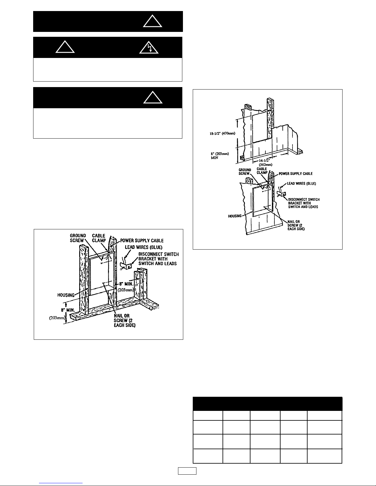
1. Provide a wall opening 14-1/2" (362mm) wide by 18-1/2"
(470mm) high at the desired mounting height, but no
closer than 8" (203mm) from floor. (See Figure 2.)
2. Power Supply Wiring
Note: Wiring Compartment Volume - 119in3 (1950cm3).
a. Run a power supply cable into the area above the top
of the wall opening. All wiring must be in accordance
with National and Local electrical codes. Refer to Table
1 for correct wire size.
b. Remove disconnect switch bracket by loosening the
two screws on the right side.
c. Install a cable clamp in the “knockout”in the top of wall
housing.
d. Insert power supply cable through cable clamp, allow-
ing approximately 6" (152mm) of cable length to
remain inside the wall housing to facilitate connections.
3. Mounting Wall Housing
a. Place the wall housing into wall opening flush with fin-
ished wall surface on bottom and sides of box. (Top
flange of wall box should protrude approximately 1/2"
or 12.7mm from finished wall surface).
b. Secure the wall housing in place with wood screws or
nails.
4. Wiring Disconnect Switch
a. Connect the power supply wires to the blue wires of the
disconnect switch using wire connectors (see wiring
diagram, pg. 3.)
b. Ground the housing using the green ground screw
located in the inside top of the housing.
c. Secure disconnect switch bracket in place by tighten-
ing screws.
IMPORTANT
CAUTION
WARNING
DO NOT INSTALL HEATER UPSIDE DOWN OR SIDE-
WAYS.
DO NOT USE HEATER WITHOUT GRILLE.
FOR WALL MOUNTING ONLY. DO NOT INSTALLHEATER
CLOSER THAN 8" (203 mm) TO THE FLOOR OR ANY
ADJACENT WALL SURFACE. DO NOT INSTALL CLOSER
THAN 36" (915 mm) TO THE CEILING.
Fig. 1: Locating Recessed Housing in New Construction
Fig. 2: Locating Recessed Housing in Existing Construction
TABLE 1
WATTS
4000
4000
4800
4800
4800
Ph
3
3
3
3
1
MODEL #
FRA 40203
FRA 40243
FRA 48203
FRA 48243
FRA 4820
VOLTS
208
240
208
240
208
WIRE SIZE
14 AWG
14 AWG
12 AWG
14AWG
10AWG
!
!
!
2
8”(203mm) MIN

Installation of Housing with
Surface-Mounting Frame (See Figure 3)
1. Secure back box to wall with knockouts in upper right
hand corner using screws and anchors.
2. Hang the surface-mounting frame on the back box.
Ensure that the back edge of the surface-mounting frame
is flush against the wall.
NOTE: If heater is located in a high traffic area, where it may
be subjected to vandalism or abuse, take extreme care to see
that the box is firmly attached to the wall.
3. Power Supply Wiring
NOTE: Wiring Compartment Volume - 119in3(1950cm3).
a. Run a power supply cable into the area to the upper
right corner of the mounting frame. Arrangement of
wiring to this point must be in accordance with National
and Local codes. Refer to specifications on page 2 for
proper wire size.
NOTE: If the wiring is to run through the wall, cut a hole
in the area of the top of the wall box. Run the supply wire
through this hole. Then remove the “knockout”from the
top of the box and proceed to step C.
b. Remove the “knockout”on the top side of the frame.
c. Remove disconnect switch bracket by loosening the
two screws on the right side.
d. Feed the power supply cable through the frame allow-
ing 6" (152mm) of lead to remain inside the inner hous-
ing (using cable clamp, connector, or other suitable
strain relief).
e. Secure the power supply cable to the inner housing
(using cable clamp, connector, or other suitable strain
relief) allowing 6" (152mm) of lead to remain inside the
inner housing.
f. Connect supply wires to blue wires of disconnect
switch using wiring connectors (see wiring diagram,
next column).
g. Ground the housing by connecting the supply ground
leadwire to the green ground screw located in the
inside top of the housing.
h. Secure disconnect switch bracket in place.
Installation of Heater Assembly and Grille
After wall housing is completely installed and no further con-
struction dirt is expected, clean debris from wall housing,
remove heater assembly from its carton, then refer to Figure
4 and proceed as follows:
1. Insert the heater assembly into wall housing, placing
the four mounting holes (with key-hole slots) over the
screws in the housing. Tighten all screws securely.
2. If surface-mounting frame is used, ensure that the
frame is even with all four heater assembly tabs before
tightening screws.
3. Connect the two disconnected switch wires to the heat-
control switch (thermostat) leads using wirenuts. (see
wiring diagram, next column) After connection, push
wires back into the opening.
4. Turn thermostat to the extreme counterclockwise
position.
5. Push disconnect switch into ON position.
6. Install (2) plastic covers on back box as follows: (See Fig. 4)
NOTE: Both top and bottom plastic covers are identical.
•TOP - Align the screw bosses on the back of the plastic
cover with the second hole down from the top of the
back box and attach it with the two screws provided.
•BOTTOM - Align the screw bosses on the back of the
other plastic cover with holes at the bottom of the back
box that are just above the fan deck mounting screws
and attach it with two screws provided.
7. Remount the wire compartment cover. Install the front
cover by hooking the (2) tabs on the one side then rotat-
ing the front cover into place making sure that all four tabs
are snapped onto the front cover.
8. Fit the thermostat knob onto the thermostat shaft and
push into place.
Fig. 3: Surface Mounting Installation
Fig. 4
ELEMENTS
FAN
MOTOR
FAN
DELAY
RELAY
DISCONNECT
FIELD WIRING
GND
THERMOSTAT MANUAL
RESET
CYC L1
1
6
8
4
6
2
1
3
2
WIRING DIAGRAM
FOR THREE PHASE WALLHEATERS
ELEMENTS
FAN
MOTOR
FAN
DELAY
RELAY
DISCONNECT
FIELD WIRING
GND
MANUAL
RESET
1
0
8
4
6
2
1
3
2
THERMOSTAT
CYC L2
WIRING DIAGRAM FOR
4800 WATT 208 VOLT
SINGLE PHASE WALLHEATER
Wiring Diagrams
MOUNT BACK BOX
TO WALL USING
REAR MOUNTING
HOLES.
HANG FRAME
ON BACK BOX. 15-5/32 "
(385mm)
19"
(482mm)
3-13/16"
(97mm)
THERMOSTAT KNOB
FRONT COVER
PLASTIC
COVER
PLASTIC COVER
POWER LEADS
BACK BOX
INNER FRAME
ASSEMBLY
RECESS WALL
HOUSING
DISCONNECT
SWITCH
THERMOSTAT
3

Operation
1. Rotate the thermostat fully clockwise. This should
energize the heating elements and cause warm air to
flow from the hot air discharge at the openings in the bot-
tom of the grille.
NOTE: This heater is provided with a fan delay control that
allows the heating element to warm prior to the fan coming
on. This delay will also allow the fan to operate for a short
period after the heating element has been turned off to
remove the residual heat from the heater.
2. After the operation check, rotate the thermostat to
the desired position to obtain room comfort.
NOTE: For best results, the heater should be left “ON”
constantly during the heating season because the thermo-
stat, when properly set, will maintain the desired tempera-
ture. Important Information
Maintenance
TO RESET MANUAL RESET LIMIT
Your heater is equipped with a manual reset safety thermal
limit control that will automatically turn the heater off to pre-
vent a fire if the heater overheats. This control is located on
the fan panel assembly between the element and fan blade
and marked “reset”. The red reset button can be seen
through the front grille when the heater is installed. To reset,
allow the heater to cool, then push the red button that is vis-
ible through the hole in the fan panel. The heater should
immediately return to normal operation.
Once each year the heater should be cleaned to remove dust
and other foreign material which has collected during the
heating season. This is a simple operation when performed
as follows:
1. Turn off the electric power at main line switch (or remove
all fuses) to disconnect electric power from the heater.
THIS IS IMPORTANT.
2. Remove thermostat knob.
3. Remove front cover by depressing plastic snap tabs with
a flat bladed screw driver as shown in Figure 5. Release
both tabs on one side then rotate the front cover off of the
fan deck.
4. With a vacuum cleaner nozzle or dust cloth, remove dust
and other foreign material.
5. After cleaning, turn disconnect switch to ON position and
reinstall the grille.
6. Turn on the main line switch (or replace fuses) to restore
power to the heater. The heater is now ready for another
season of operation.
LIMITED WARRANTY
All products manufactured by Marley Engineered Products are warranted against defects in workmanship and materials for one year from date of installation, except
heating elements which are warranted against defects in workmanship and materials for five years from date of installation. This warranty does not apply to damage
from accident, misuse, or alteration; nor where the connected voltage is more than 5% above the nameplate voltage; nor to equipment improperly installed or wired or
maintained in violation of the product’s installation instructions.All claims for warranty work must be accompanied by proof of the date of installation.
The customer shall be responsible for all costs incurred in the removal or reinstallation of products, including labor costs, and shipping costs incurred to return prod-
ucts to Marley Engineered Products Service Center. Within the limitations of this warranty, inoperative units should be returned to the nearest Marley authorized ser-
vice center or the Marley Engineered Products Center, and we will repair or replace, at our option, at no charge to you with return freight paid by Marley. It is agreed
that such repair or replacement is the exclusive remedy available from Marley Engineered Products.
THE ABOVE WARRANTIES ARE IN LIEU OF ALL OTHER WARRANTIES EXPRESSED OR IMPLIED. AND ALL IMPLIED WARRANTIES OF MERCHANTABILITY
AND FITNESS FOR A PARTICULAR PURPOSE WHICH EXCEED THE AFORESAID EXPRESSED WARRANTIES ARE HEREBY DISCLAIMED AND EXCLUDED
FROM THISAGREEMENT. MARLEY ENGINEERED PRODUCTS SHALLNOT BE LIABLE FOR CONSEQUENTIALDAMAGES ARISING WITH RESPECT TO THE
PRODUCT, WHETHER BASED UPON NEGLIGENCE, TORT, STRICT LIABILITY, OR CONTRACT.
Some states do allow the exclusion or limitation of incidental or consequential damages, so the above exclusion or limitation may not apply to you. This warranty gives
you specific legal rights, and you may also have other rights which vary from state to state.
For the address of your nearest authorized service center, contact Marley Engineered Products in Bennettsville, SC, at 1-800-642-4328. Merchandise returned to the
factory must be accompanied by a return authorization and service identification tag, both available from Marley Engineered Products. When requesting return autho-
rization, include all catalog numbers shown on the products.
CAUTION
OPERATION OFTHE MANUAL RESET SAFETYTHERMALLIMIT
CONTROL IS AN INDICATION THAT THE HEATER HAS BEEN
SUBJECTED TO SOME ABNORMAL CONDITION. IT IS RECOM-
MENDED THAT THE HEATER BE CHECKED BY A REPUTABLE
ELECTRICIAN OR REPAIR SERVICE TO ENSURE THE HEATER
HAS NOT BEEN DAMAGED.
CAUTION
DO NOT USE WATER OR DAMP CLOTH FOR CLEANING AND
DO NOT DISTURB THE HEATING ELEMENT.
MODEL NO. FRA40203 DATE CODE: 0695
FAN FORCED WALL HEATER
APPAREIL DE CHAUFFAGE MURAL ÀAIR PLUSÉ
VOLTS AC 60HZ WATTS PHASE
HI LO
208 4800 3
MUST BE USED WITH AWH-BB BACK BOX
DO NOT OPERATE WITHOUT FRONT COVER IN PLACE.
DOIT ÉTRE UTILISÉAVEC BOÎTIER ARRIÈRE AWH-BB
NE PAS UTILISER SI LE COUVERCLE AVANT N’EST PAS EN PLACE.
MARLEY ENGINEERED PRODUCTS
BENNETTSVILLE, SC 29512
7746 LISTED
ROOM HEATER
!
!
HOWTO ORDER REPAIR PARTS
In order to obtain any needed repair or replacement
parts, warranty service or technical information, please
contact Marley Engineered Products Service Center toll-
free by calling 1-800-642-HEAT.
When ordering repair parts, always give the informa-
tion listed as follows:
1. The Part Number
2. The Model Number
3. The Part Description
4. Date of Manufacture
07/95
Part No. 5200-2264-000 4
SWO 244
SPX Corporation
470 Beauty Spot Rd. East
Bennettsville, SC 29512 USA
Table of contents
Other Berko Heater manuals


Popular Heater manuals by other brands

Klarstein
Klarstein WONDERWALL 45 manual

simatherm
simatherm IH 045 Quick installation guide

Dimplex
Dimplex RCE 050 Installation and operating instructions

STIEBEL ELTRON
STIEBEL ELTRON CK 20 S Operation and installation manual

Ankersmid Sampling
Ankersmid Sampling AHL Series user manual

EUROM
EUROM The Box 2400 instruction manual

Exo Terra
Exo Terra PT2015 operating instructions

Prem-I-Air
Prem-I-Air EH1524 User and installation guide

Trane
Trane BAYHTR1504BRKC Installer's guide

lazzarini
lazzarini Cortina User and installation manual

Frico
Frico Thermocassette HP300 Assembly and operating instructions

Infratech
Infratech SL 1612 Installation, use & care manual


