Bernecker + Rainer 5AP923.1215-00 User manual

1
Automation Panel 9x3
User's manual
Version: 1.16 (November 2015)
Model no.: MAAP9x3-ENG
All information contained in this manual is current as of its creation/publication. B&R reserves the right to change
the contents of this manual without notice. The information contained herein is believed to be accurate as of
the date of publication; however, Bernecker + Rainer Industrie-Elektronik Ges.m.b.H. makes no warranty, ex-
pressed or implied, with regard to the products or documentation contained within this manual. In addition,
Bernecker + Rainer Industrie-Elektronik Ges.m.b.H. shall not be liable for any incidental or consequential damages
in connection with or arising from the furnishing, performance or use of the product(s) in this documentation. Soft-
ware names, hardware names and trademarks are registered by their respective companies.


Table of contents
Table of contents
Automation Panel 9x3 user's manual V1.16 3
Chapter 1 General information................................................................................... 7
1 Manual history....................................................................................................................................................7
2 Safety guidelines................................................................................................................................................8
2.1 Intended use.................................................................................................................................................8
2.2 Protection against electrostatic discharge....................................................................................................8
2.2.1 Packaging................................................................................................................................................8
2.2.2 Guidelines for proper ESD handling.......................................................................................................8
2.3 Policies and procedures...............................................................................................................................8
2.4 Transport and storage..................................................................................................................................9
2.5 Installation.....................................................................................................................................................9
2.6 Operation...................................................................................................................................................... 9
2.6.1 Protection against touching electrical parts............................................................................................9
2.6.2 Environmental conditions - Dust, moisture, corrosive gases..................................................................9
2.6.3 Viruses and dangerous programs.......................................................................................................... 9
2.7 Environmentally friendly disposal............................................................................................................... 10
2.7.1 Separation of materials.........................................................................................................................10
3 Organization of safety notices......................................................................................................................... 11
4 Guidelines.........................................................................................................................................................11
5 Overview...........................................................................................................................................................12
Chapter 2 Technical data.......................................................................................... 13
1 Introduction.......................................................................................................................................................13
1.1 About this user's manual............................................................................................................................13
1.2 Description of individual modules...............................................................................................................13
1.2.1 Display units AP9x3..............................................................................................................................13
1.2.2 Link modules.........................................................................................................................................13
1.3 Structure/Configuration............................................................................................................................... 14
1.3.1 Configuration......................................................................................................................................... 14
2 Complete system............................................................................................................................................. 15
2.1 Connection options.....................................................................................................................................15
2.1.1 SDL mode............................................................................................................................................. 15
2.1.2 DVI mode.............................................................................................................................................. 17
2.1.3 SDL3 mode........................................................................................................................................... 18
2.2 Mechanical characteristics..........................................................................................................................19
2.2.1 Dimensions............................................................................................................................................19
2.2.2 Installation diagrams............................................................................................................................. 20
2.2.3 Spacing for air circulation..................................................................................................................... 21
2.2.4 Mounting orientations............................................................................................................................22
2.2.5 Weight specifications............................................................................................................................ 22
2.3 Environmental characteristics.....................................................................................................................23
2.3.1 Temperature specifications................................................................................................................... 23
2.3.2 Relative humidity...................................................................................................................................25
2.3.3 Vibration................................................................................................................................................ 25
2.3.4 Shock.....................................................................................................................................................25
2.3.5 Protection.............................................................................................................................................. 25
2.4 Electrical characteristics............................................................................................................................. 26
2.4.1 +24 VDC voltage supply.......................................................................................................................26
2.4.2 Power calculation.................................................................................................................................. 26
2.4.3 Block diagrams......................................................................................................................................27
2.5 SDL/DVI receiver - 5DLSDL.1001-00 device interfaces............................................................................ 28
2.5.1 Overview................................................................................................................................................28
2.5.2 +24 VDC voltage supply.......................................................................................................................29
2.5.3 Panel In interface..................................................................................................................................30
2.5.4 USB interfaces...................................................................................................................................... 32
2.5.5 USB In interface....................................................................................................................................33
2.5.6 COM serial interface............................................................................................................................. 33
2.5.7 Brightness controls................................................................................................................................33

Table of contents
4 Automation Panel 9x3 user's manual V1.16
2.6 5DLSD3.1001-00 SDL/DVI receiver - Device interfaces............................................................................34
2.6.1 Overview................................................................................................................................................34
2.6.2 +24 VDC voltage supply.......................................................................................................................35
2.6.3 SDL3 In interface.................................................................................................................................. 36
2.6.4 SDL3 In LEDs....................................................................................................................................... 36
2.6.5 USB interfaces...................................................................................................................................... 37
3 Individual components..................................................................................................................................... 38
3.1 Display units............................................................................................................................................... 38
3.1.1 5AP923.1215-00....................................................................................................................................38
3.1.2 5AP923.1505-00....................................................................................................................................40
3.1.3 5AP923.1906-00....................................................................................................................................42
3.1.4 5AP933.156B-00................................................................................................................................... 44
3.1.5 5AP933.185B-00................................................................................................................................... 46
3.1.6 5AP933.215C-00................................................................................................................................... 48
3.1.7 5AP933.240C-00................................................................................................................................... 50
3.2 Link modules.............................................................................................................................................. 52
3.2.1 5DLSDL.1001-00...................................................................................................................................52
3.2.2 5DLSD3.1001-00...................................................................................................................................53
Chapter 3 Installation.................................................................................................54
1 Installation........................................................................................................................................................ 54
1.1 Mounting an Automation Panel 9x3...........................................................................................................54
1.2 Replacing link modules.............................................................................................................................. 56
2 Connecting to the power mains.......................................................................................................................57
2.1 Installing the DC power cable.................................................................................................................... 57
2.1.1 Wiring.................................................................................................................................................... 57
2.2 Connecting the power supply to a B&R device......................................................................................... 58
2.3 Functional ground - Grounding concept.....................................................................................................59
3 Cable connections............................................................................................................................................60
4 Switching on the device for the first time........................................................................................................ 61
4.1 General information before switching on the device..................................................................................61
4.2 Switching on the Automation Panel........................................................................................................... 61
5 Touch screen calibration.................................................................................................................................. 62
5.1 Single-touch (analog resistive)................................................................................................................... 62
5.1.1 Windows Embedded 8.1 Industry Pro.................................................................................................. 62
5.1.2 Windows 7 Professional / Ultimate.......................................................................................................62
5.1.3 Windows Embedded Standard 7 Embedded / Premium......................................................................62
5.1.4 Windows XP Professional.....................................................................................................................62
5.1.5 Windows Embedded Standard 2009.................................................................................................... 62
5.2 Multi-touch (projected capacitive - PCT)....................................................................................................62
5.2.1 Windows Embedded 8.1 Industry Pro.................................................................................................. 62
5.2.2 Windows 7 Professional / Ultimate.......................................................................................................62
5.2.3 Windows Embedded Standard 7 Premium...........................................................................................62
6 Adjusting the display brightness...................................................................................................................... 63
6.1 Adjusting in SDL/SDL3 mode.................................................................................................................... 63
6.2 Adjusting in DVI mode............................................................................................................................... 63
Chapter 4 Software.................................................................................................... 64
1 Upgrade information.........................................................................................................................................64
1.1 Firmware upgrade...................................................................................................................................... 64
2 Automation Runtime.........................................................................................................................................64
2.1 General information.................................................................................................................................... 64
2.2 Automation Runtime Embedded (ARemb).................................................................................................64
3 B&R Automation Device Interface (ADI) - Control Center...............................................................................65
3.1 Functions.................................................................................................................................................... 65
3.2 Installation...................................................................................................................................................66
4 B&R Automation Device Interface (ADI) Development Kit..............................................................................67

Table of contents
Table of contents
Automation Panel 9x3 user's manual V1.16 5
5 B&R Automation Device Interface (ADI) .NET SDK........................................................................................69
6 B&R Key Editor................................................................................................................................................71
7 B&R KCF Editor...............................................................................................................................................73
8 HMI Service Center......................................................................................................................................... 74
8.1 5SWUTI.0001-000...................................................................................................................................... 74
8.1.1 General information...............................................................................................................................74
8.1.2 Order data.............................................................................................................................................74
Chapter 5 Standards and certifications................................................................... 75
1 Standards and guidelines................................................................................................................................ 75
1.1 CE mark......................................................................................................................................................75
1.2 EMC directive............................................................................................................................................. 75
1.3 Low voltage directive..................................................................................................................................75
2 Certifications.....................................................................................................................................................76
2.1 UL certification............................................................................................................................................76
2.2 UL Haz. Loc. Certifications........................................................................................................................ 76
2.3 GOST-R...................................................................................................................................................... 76
Chapter 6 Accessories.............................................................................................. 77
1 Power connectors............................................................................................................................................ 77
1.1 0TB103.9x...................................................................................................................................................77
1.1.1 General information...............................................................................................................................77
1.1.2 Order data.............................................................................................................................................77
1.1.3 Technical data.......................................................................................................................................77
2 USB flash drives.............................................................................................................................................. 79
2.1 5MMUSB.xxxx-01....................................................................................................................................... 79
2.1.1 General information...............................................................................................................................79
2.1.2 Order data.............................................................................................................................................79
2.1.3 Technical data.......................................................................................................................................79
2.1.4 Temperature/Humidity diagram.............................................................................................................80
3 Cables.............................................................................................................................................................. 81
3.1 DVI cables.................................................................................................................................................. 81
3.1.1 5CADVI.0xxx-00.................................................................................................................................... 81
3.2 SDL cables................................................................................................................................................. 84
3.2.1 5CASDL.0xxx-00................................................................................................................................... 84
3.3 SDL cables with 45° male connector.........................................................................................................87
3.3.1 5CASDL.0xxx-01................................................................................................................................... 87
3.4 SDL flex cables.......................................................................................................................................... 90
3.4.1 5CASDL.0xxx-03................................................................................................................................... 90
3.5 SDL flex cables with extender................................................................................................................... 93
3.5.1 5CASDL.0xx0-13...................................................................................................................................93
3.6 SDL3 cables............................................................................................................................................... 97
3.6.1 5CASD3.xxxx-00................................................................................................................................... 97
3.7 USB cables...............................................................................................................................................100
3.7.1 5CAUSB.00xx-00................................................................................................................................ 100
3.8 RS232 cables........................................................................................................................................... 101
3.8.1 9A0014.xx.......................................................................................................................................... 101
Chapter 7 Maintenance and service.......................................................................103
1 Cleaning......................................................................................................................................................... 103
2 Tips for extending the service life of the display........................................................................................... 104
2.1 Backlight................................................................................................................................................... 104
2.1.1 How can the service life of the backlight be extended?.....................................................................104
2.2 Screen burn-in.......................................................................................................................................... 104
2.2.1 What causes screen burn-in?.............................................................................................................104
2.2.2 How can screen burn-in be avoided?.................................................................................................104
3 Pixel errors..................................................................................................................................................... 104

Table of contents
6 Automation Panel 9x3 user's manual V1.16
Appendix A .............................................................................................................. 105
1 Abbreviations..................................................................................................................................................105
2 Viewing angles...............................................................................................................................................105
3 Chemical resistance.......................................................................................................................................106
3.1 Autotex panel overlay (polyester).............................................................................................................107
3.2 Aluminum panel overlay........................................................................................................................... 108
3.3 Coated aluminum front............................................................................................................................. 108
3.4 Touch screen............................................................................................................................................ 109
4 Touch screen..................................................................................................................................................110
4.1 5-wire AMT touch screen (single-touch).................................................................................................. 110
4.1.1 Technical data.....................................................................................................................................110
4.1.2 Temperature/Humidity diagram...........................................................................................................110
4.2 3M touch screen (multi-touch)..................................................................................................................111
4.2.1 Technical data.....................................................................................................................................111
4.2.2 Temperature/Humidity diagram...........................................................................................................111

General information • Manual history
Chapter 1
General information
Automation Panel 9x3 user's manual V1.16 7
Chapter 1 • General information
1 Manual history
Version Date Change
1.00 2013-12-10 •First version
1.05 2014-04-16 •Revised Fig. X "Temperatur max" on page .
•Updated chapter 4 "Software" on page 64.
•Updated GOST-R certification information in the technical data.
•Updated section "GOST-R" on page 76 in chapter 5 "Standards and certifications".
•Respecified maximum nominal current of link module from 2.5 A to 3 A.
•Updated SDL3 link module "5DLSD3.1001-00" on page 53.
•Updated SDL3 cables "5CASD3.xxxx-00" on page 97.
•Updated section "Chemical resistance" on page 106.
•Updated section "Touch screen" on page 110.
1.10 2014-10-23 •Updated section "SDL3 In LEDs" on page 36.
•Updated Fig. X "Temperatur max" on page .
•Updated sections "B&R Automation Device Interface (ADI) Development Kit" on page 67 and "B&R
Automation Device Interface (ADI) .NET SDK" on page 69.
•Updated "B&R Key Editor" on page 71.
•Changed panel overlay design of single-touch display units, see "5AP923.1215-00" on page 38,
"5AP923.1505-00" on page 40 and "5AP923.1906-00" on page 42.
•Updated section Chemical resistance.
1.11 2014-12-18 •Updated section "Maximum ambient temperature during operation" on page 23 and Tab. 14 "Temper-
ature sensor position" on page 24.
•Updated section "Protection" on page 25.
•Updated technical data for display units (operating conditions), see "Display units" on page 38.
1.15 2015-10-16 •Updated section "UL Haz. Loc. Certifications" on page 76 and UL HazLoc certification for technical
data of certain individual components.
•Updated SDL cable 5CASDL.0008-00, see "SDL cables" on page 84.
•Updated "B&R KCF Editor" on page 73.
•Updated "B&R Key Editor" on page 71 to version 3.60.
•Updated "HMI Service Center" on page 74 (5SWUTI.0001-000).
•Modified section "Protection" on page 25.
•Updated technical data and temperature humidity diagrams for "Display units" on page 38.
•Updated SDL3 cable 5CASD3.0050-00, see "SDL3 cables" on page 97.
•Updated "3M touch screen - Temperature/Humidity diagram" on page 111.
•Updated section "Power calculation" on page 26.
•Updated section "Ambient temperature during storage and transport" on page 24.
1.16 2015-11-04 •Updated section "Automation Runtime" on page 64.
Table 1: Manual history

General information • Safety guidelines
8 Automation Panel 9x3 user's manual V1.16
2 Safety guidelines
2.1 Intended use
Programmable logic controllers (PLCs), operating/monitoring devices (industrial PCs, Power Panels, Mobile Pan-
els, etc.) and B&R uninterruptible power supplies have been designed, developed and manufactured for conven-
tional use in industrial environments. They were not designed, developed and manufactured for any use involving
serious risks or hazards that could lead to death, injury, serious physical damage or loss of any kind without the
implementation of exceptionally stringent safety precautions. In particular, such risks and hazards include the use
of these devices to monitor nuclear reactions in nuclear power plants, their use in flight control or flight safety sys-
tems as well as in the control of mass transportation systems, medical life support systems or weapons systems.
2.2 Protection against electrostatic discharge
Electrical components that can be damaged by electrostatic discharge (ESD) must be handled accordingly.
2.2.1 Packaging
•Electrical components with a housing
...do not require special ESD packaging but must be handled properly (see "Electrical components with
a housing").
•Electrical components without a housing
…are protected by ESD-suitable packaging.
2.2.2 Guidelines for proper ESD handling
Electrical components with a housing
•Do not touch the connector contacts on connected cables.
•Do not touch the contact tips on circuit boards.
Electrical components without a housing
The following applies in addition to the points listed under "Electrical components with a housing":
•Any persons handling electrical components or devices with installed electrical components must be
grounded.
•Components are only permitted to be touched on their narrow sides or front plate.
•Components should always be stored in a suitable medium (ESD packaging, conductive foam, etc.). Metal-
lic surfaces are not suitable storage surfaces!
•Components should not be subjected to electrostatic discharge (e.g. through the use of charged plastics).
•Ensure a minimum distance of 10 cm from monitors and TV sets.
•Measuring instruments and equipment must be grounded.
•Probes on potential-free measuring instruments must be discharged on sufficiently grounded surfaces be-
fore taking measurements.
Individual components
•ESD protective measures for individual components are thoroughly integrated at B&R (conductive floors,
footwear, arm bands, etc.).
•These increased ESD protective measures for individual components are not necessary for customers
handling B&R products.
2.3 Policies and procedures
Electronic devices are never completely failsafe. If the programmable control system, operating/monitoring device
or uninterruptible power supply fails, the user is responsible for ensuring that other connected devices, e.g. motors,
are brought to a secure state.

General information • Safety guidelines
Chapter 1
General information
Automation Panel 9x3 user's manual V1.16 9
When using programmable logic controllers or operating/monitoring devices as control systems together with a soft
PLC (e.g. B&R Automation Runtime or comparable product) or slot PLC (e.g. B&R LS251 or comparable product),
safety precautions relevant to industrial control systems (e.g. the provision of safety devices such as emergency
stop circuits, etc.) must be observed in accordance with applicable national and international regulations. The same
applies for all other devices connected to the system, such as drives.
All tasks such as the installation, commissioning and servicing of devices are only permitted to be carried out by
qualified personnel. Qualified personnel are those familiar with the transport, mounting, installation, commissioning
and operation of devices who also have the appropriate qualifications (e.g. IEC 60364). National accident preven-
tion regulations must be observed.
The safety notices, connection descriptions (type plate and documentation) and limit values listed in the technical
data are to be read carefully before installation and commissioning and must be observed.
2.4 Transport and storage
During transport and storage, devices must be protected against undue stress (mechanical loads, temperature,
moisture, corrosive atmospheres, etc.).
2.5 Installation
•These devices are not ready for use upon delivery and must be installed and wired according to the spec-
ifications in this documentation in order for the EMC limit values to apply.
•Installation must be performed according to this documentation using suitable equipment and tools.
•Devices are only permitted to be installed by qualified personnel without voltage applied. Before installation,
voltage to the control cabinet must be switched off and prevented from being switched on again.
•General safety guidelines and national accident prevention regulations must be observed.
•Electrical installation must be carried out in accordance with applicable guidelines (e.g. line cross sections,
fuses, protective ground connections).
2.6 Operation
2.6.1 Protection against touching electrical parts
To operate programmable logic controllers, operating and monitoring devices, and uninterruptible power supplies,
certain components must carry dangerous voltage levels. Touching one of these parts can result in a life-threatening
electric shock. This could lead to death, severe injury or damage to equipment.
Before turning on the programmable logic controller, operating/monitoring devices or uninterruptible power supply,
the housing must be properly grounded (PE rail). Ground connections must be established even when testing or
operating operating/monitoring devices or the uninterruptible power supply for a short time!
Before turning the device on, all parts that carry voltage must be securely covered. During operation, all covers
must remain closed.
2.6.2 Environmental conditions - Dust, moisture, corrosive gases
The use of operating/monitoring devices (e.g. industrial PCs, Power Panels, Mobile Panels, etc.) and uninterruptible
power supplies in very dusty environments should be avoided. Dust collection on the devices can affect functionality
and may prevent sufficient cooling, especially in systems with active cooling systems (fans).
The presence of corrosive gases can also lead to malfunctions. When combined with high temperature and hu-
midity, corrosive gases – e.g. with sulfur, nitrogen and chlorine components – can induce chemical reactions that
can damage electronic components very quickly. Signs of the presence of corrosive gases are blackened copper
surfaces and cable ends on existing equipment.
For operation in dusty or moist conditions, correctly installed (e.g. cutout installations) operating/monitoring devices
like the Automation Panel or Power Panel are protected on the front. The back of all devices must be protected
from dust and moisture and cleaned at suitable intervals.
2.6.3 Viruses and dangerous programs
This system is subject to potential risk each time data is exchanged or software is installed from a data medium
(e.g. diskette, CD-ROM, USB flash drive, etc.), a network connection or the Internet. The user is responsible for
assessing these dangers, implementing preventive measures such as virus protection programs, firewalls, etc. and
making sure that software is only obtained from trusted sources.

General information • Safety guidelines
10 Automation Panel 9x3 user's manual V1.16
2.7 Environmentally friendly disposal
All B&R programmable controllers, operating/monitoring devices and uninterruptible power supplies are designed
to inflict as little harm as possible on the environment.
2.7.1 Separation of materials
It is necessary to separate different materials so the device can undergo an environmentally friendly recycling
process.
Component Disposal
Programmable logic controllers
Operating/Monitoring devices
Uninterruptible power supply
Batteries and rechargeable batteries
Cables
Electronics recycling
Cardboard box / Paper packaging Cardboard box / Paper recycling
Plastic packaging Plastic recycling
Table 2: Environmentally friendly separation of materials
Disposal must comply with applicable legal regulations.
General information • Guidelines
Chapter 1
General information
Automation Panel 9x3 user's manual V1.16 11
3 Organization of safety notices
Safety notices in this manual are organized as follows:
Safety notice Description
Danger! Disregarding these safety guidelines and notices can be life-threatening.
Warning! Disregarding these safety guidelines and notices can result in severe injury or substantial damage to equipment.
Caution! Disregarding these safety guidelines and notices can result in injury or damage to equipment.
Information: This information is important for preventing errors.
Table 3: Description of the safety notices used in this documentation
4 Guidelines
E
European dimension standards apply to all dimension diagrams in this document.
All dimensions are specified in mm.
Range of nominal sizes General tolerance according to
DIN ISO 2768 (medium)
Up to 6 mm ±0.1 mm
For 6 to 30 mm ±0.2 mm
For 30 to 120 mm ±0.3 mm
For 120 to 400 mm ±0.5 mm
For 400 to 1000 mm ±0.8 mm
Table 4: Range of nominal sizes
General information • Overview
12 Automation Panel 9x3 user's manual V1.16
5 Overview
Product ID Short description on page
Accessories
5SWUTI.0001-000 HMI Service Center USB Flash Drive - Hardware diagnostics software - For APC810/PPC800 - For APC910/
PPC900 - For APC2100/PPC2100 - For APC51x/PP500 - For Automation Panel 800/900
74
DVI cables
5CADVI.0018-00 DVI-D cable - 1.8 m 81
5CADVI.0050-00 DVI-D cable - 5 m 81
5CADVI.0100-00 DVI-D cable - 10 m 81
Display units
5AP923.1215-00 Automation Panel 12.1" XGA TFT - 1024 x 768 pixels (4:3) - Single-touch (analog resistive) - Control cabinet
installation - Landscape format - For PPC900 / PPC2100 / Link modules
38
5AP923.1505-00 Automation Panel 15.0" XGA TFT - 1024 x 768 pixels (4:3) - Single-touch (analog resistive) - Control cabinet
installation - Landscape format - For PPC900 / PPC2100 / Link modules
40
5AP923.1906-00 Automation Panel 19.0" SXGA TFT - 1280 x 1024 pixels (4:3) - Single-touch (analog resistive) - Control cabinet
installation - Landscape format - For PPC900 / PPC2100 / Link modules
42
5AP933.156B-00 Automation Panel 15.6" HD TFT - 1366 x 768 pixels (16:9) - Multi-touch (projected capacitive) - Control cabinet
installation - Landscape format - For PPC900 / PPC2100 / Link modules
44
5AP933.185B-00 Automation Panel 18.5" HD TFT - 1366 x 768 pixels (16:9) - Multi-touch (projected capacitive) - Control cabinet
installation - Landscape format - For PPC900 / PPC2100 / Link modules
46
5AP933.215C-00 Automation Panel 21.5" Full HD TFT - 1920 x 1080 pixels (16:9) - Multi-touch (projected capacitive) - Control
cabinet installation - Landscape format - For PPC900 / PPC2100 / Link modules
48
5AP933.240C-00 Automation Panel 24.0" Full HD TFT - 1920 x 1080 pixels (16:9) - Multi-touch (projected capacitive) - Control
cabinet installation - Landscape format - For PPC900 / PPC2100 / Link modules
50
Link modules
5DLSD3.1001-00 Automation Panel link module - SDL3 receiver - For Automation Panel 923/933/1000 53
5DLSDL.1001-00 Automation Panel link module - SDL/DVI receiver - For Automation Panel 923/933/1000 52
RS232 cables
9A0014.02 RS232 extension cable for remote operation of a display unit with touch screen, 1.8 m 101
9A0014.05 RS232 extension cable for remote operation of a display unit with touch screen, 5 m 101
9A0014.10 RS232 extension cable for remote operation of a display unit with touch screen, 10 m 101
SDL cables
5CASDL.0008-00 SDL cable - 0.8 m 84
5CASDL.0018-00 SDL cable - 1.8 m 84
5CASDL.0050-00 SDL cable - 5 m 84
5CASDL.0100-00 SDL cable - 10 m 84
5CASDL.0150-00 SDL cable - 15 m 84
5CASDL.0200-00 SDL cable - 20 m 84
5CASDL.0250-00 SDL cable - 25 m 84
5CASDL.0300-00 SDL cable - 30 m 84
SDL cables with 45° connectors
5CASDL.0018-01 SDL cable - 45 degree connector - 1.8 m 87
5CASDL.0050-01 SDL cable - 45 degree connector - 5 m 87
5CASDL.0100-01 SDL cable - 45 degree connector - 10 m 87
5CASDL.0150-01 SDL cable - 45 degree connector - 15 m 87
SDL flex cables
5CASDL.0018-03 SDL flex cable - 1.8 m 90
5CASDL.0050-03 SDL flex cable - 5 m 90
5CASDL.0100-03 SDL flex cable - 10 m 90
5CASDL.0150-03 SDL flex cable - 15 m 90
5CASDL.0200-03 SDL flex cable - 20 m 90
5CASDL.0250-03 SDL flex cable - 25 m 90
5CASDL.0300-03 SDL flex cable - 30 m 90
5CASDL.0300-13 SDL flex cable with extender - 30 m 93
5CASDL.0400-13 SDL flex cable with extender - 40 m 93
5CASDL.0430-13 SDL flex cable with extender - 43 m 93
SDL3 cables
5CASD3.0050-00 SDL3 cable - 5 m 97
5CASD3.0100-00 SDL3 cable - 10 m 97
5CASD3.0150-00 SDL3 cable - 15 m 97
5CASD3.0200-00 SDL3 cable - 20 m 97
5CASD3.0300-00 SDL3 cable - 30 m 97
5CASD3.0500-00 SDL3 cable - 50 m 97
5CASD3.1000-00 SDL3 cable - 100 m 97
Terminal blocks
0TB103.9 Connector 24 VDC - 3-pin female - Screw clamps 3.31 mm² 77
0TB103.91 Connector 24 VDC - 3-pin female - Cage clamp terminal block 3.31 mm² 77
USB accessories
5MMUSB.2048-01 USB 2.0 flash drive, 2048 MB, B&R 79
5MMUSB.4096-01 USB 2.0 flash drive, 4096 MB, B&R 79
USB cables
5CAUSB.0018-00 USB 2.0 connection cable - Type A - Type B connector - 1.8 m 100
5CAUSB.0050-00 USB 2.0 connection cable - Type A - Type B connector - 5 m 100

Technical data • Introduction
Chapter 2
Technical data
Automation Panel 9x3 user's manual V1.16 13
Chapter 2 • Technical data
1 Introduction
1.1 About this user's manual
This user's manual contains all relevant information about an operational Automation Panel 9x3 built-in device.
This user's manual applies to the modular Automation Panel 9x3 product generation. Information about Automation
Panel 920, 980, 981 and 982 systems can be found in the Automation Panel 900 user's manual.
1.2 Description of individual modules
1.2.1 Display units AP9x3
AP9x3 display units consist of a display and touch screen and form the basis for the Automation Panel 9x3, Panel
PC 900 and Panel PC 2100 system families. Different display sizes and touch screen technologies are available.
These display units can only be operated as a complete system together with a link module (Automation Panel
9x3) or CPU board and system unit (Panel PC 900, Panel PC 2100).
Model numbers for single-touch display units begin with 5AP923.xxxx-xx; those for multi-touch display units begin
with 5AP933.xxxx-xx.
1.2.2 Link modules
Link modules have various graphics interfaces and connections. An Automation Panel 9x3 or Automation Panel
1000 is put together by installing a link module onto a display unit. Automation Panel systems are mounted using
retaining clips.
A link module cannot be operated without a display unit.
Technical data • Introduction
14 Automation Panel 9x3 user's manual V1.16
1.3 Structure/Configuration
Automation Panel 9x3, Panel PC 900 and Panel PC 2100 systems can be assembled to meet individual require-
ments and operating conditions. Automation Panel 9x3, Panel PC 900 and Panel PC 2100 systems are so flexible
that an Automation Panel can be converted to a Panel PC, or vice versa.
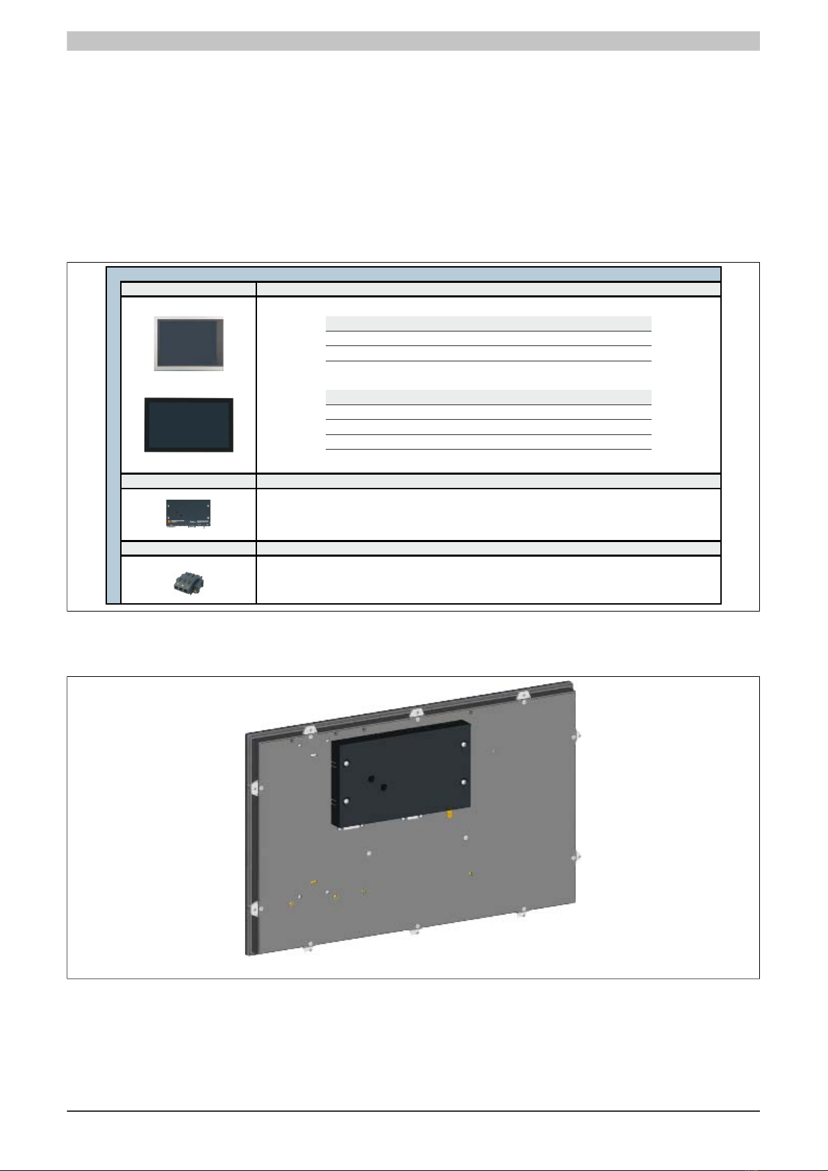
1.3.1 Configuration
The following components are required for operation as an Automation Panel 9x3:
•Display unit
•Link module
Display unit
Configuration - Base system
Select 1
5DLSDL.1001-00 SDL/DVI receiver
5DLSD3.1001-00 SDL3 receiver
Link module Select 1
Select 1
Terminal blocks
0TB103.9
0TB103.91
Power connectors
Display size
Resolution
Touch screen
Automation Panel 923
5AP923.1215-00
12.1"
XGA
Single-touch
5AP923.1505-00
15.0"
XGA
Single-touch
5AP923.1906-00
19.0"
SXGA
Single-touch
Automation Panel 933
5AP933.156B-00
15.6"
HD
Multi-touch
5AP933.185B-00
18.5"
HD
Multi-touch
5AP933.215C-00
21.5"
FHD
Multi-touch
5AP933.240C-00
24.0"
FHD
Multi-touch
Figure 1: Automation Panel 9x3 - Configuration
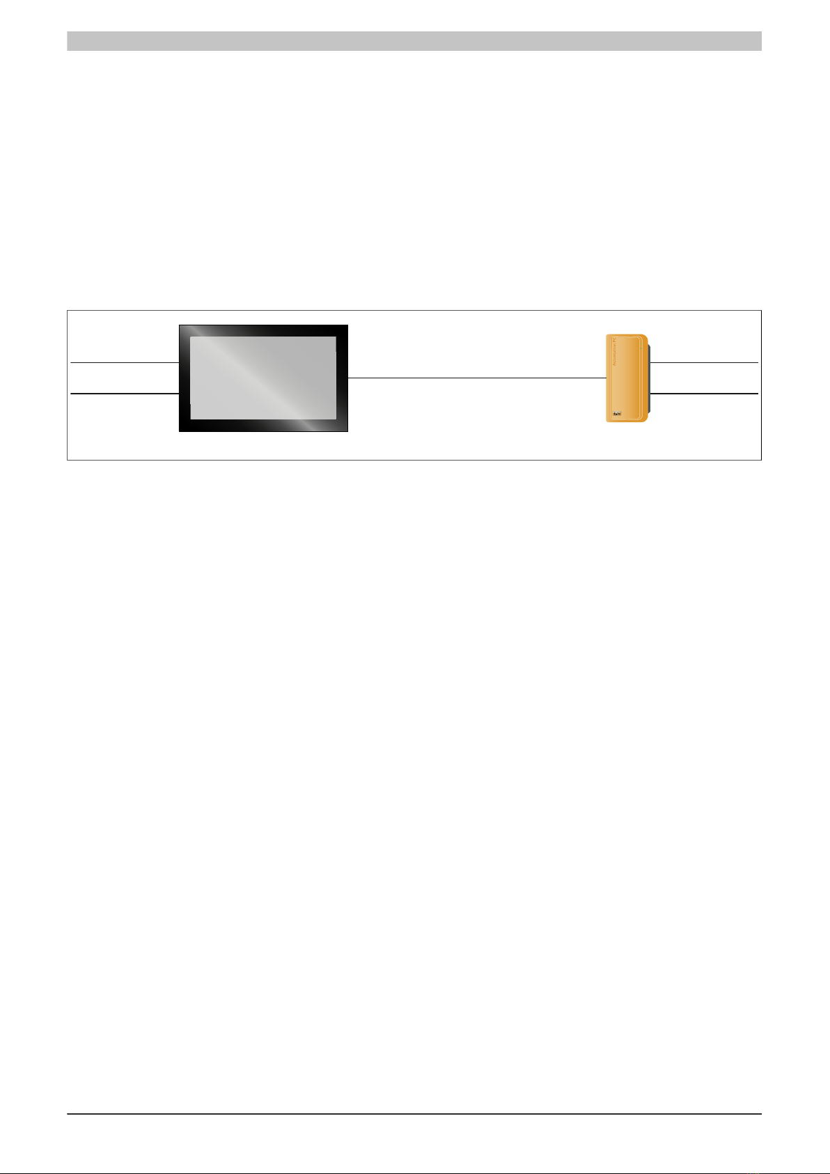
Configuration options
Automation Panel 9x3 with SDL/DVI link module
Figure 2: Automation Panel 9x3 - Display unit and link module

Technical data • Complete system
Chapter 2
Technical data
Automation Panel 9x3 user's manual V1.16 15
2 Complete system
2.1 Connection options
The Automation Panel can be connected to a B&R Industrial PC via SDL, DVI or SDL3. The connection options
listed below provide an overview of the operating modes and possible limitations.
2.1.1 SDL mode
2.1.1.1 SDL mode - Mode 1
SDL mode 1 allows all communication between the Automation Panel and a B&R Industrial PC to be handled
using a single SDL cable.
It is used to transfer not just display data, but touch screen, matrix key, LED, service and diagnostic data as well.
The Automation Panel can be installed up to 40 m from the B&R Industrial PC. USB 1.1 is fully integrated in SDL
and transferred over this distance as well without requiring any external modules.
The display's brightness can be configured using the ADI Control Center.
Automation Panel
with SDL/DVI receiver
B&R Industrial PC
SDL cable
SDL mode 1
Power supply
Grounding
Power supply
Grounding
Availability of interfaces on the Automation Panel with SDL/DVI receiver:
Panel In ✓USB In xPower supply ✓Brightness controls x
USB1, USB2 ✓ USB 1.1 COM touch interface xGrounding ✓
Maximum cable length: 40 m
Prerequisites and requirements
•Automation Panel with SDL/DVI receiver
•B&R Industrial PC with SDL interface
•SDL cable

Technical data • Complete system
16 Automation Panel 9x3 user's manual V1.16
2.1.1.2 SDL mode - Mode 2
In SDL mode 2, communication between the Automation Panel and the B&R Industrial PC is handled using an
SDL cable connected to the Panel In interface and a USB type A/B cable connected to the USB In interface.
In addition to display data, the SDL cable is used to transfer resistive touch screen, matrix key and service/diag-
nostic data. Data from multi-touch touch screens is transferred over the USB type A/B cable. The Automation Panel
can be installed up to 5 m (USB specification) from the B&R Industrial PC. USB 2.0 data can be transferred over
the USB type A/B cable for this distance without requiring any external modules.
The display's brightness can be configured using the ADI Control Center.
SDL cable
USB type A/B cable
Automation Panel
with SDL/DVI receiver
SDL mode 2
B&R Industrial PC
Power supply
Grounding
Power supply
Grounding
Availability of interfaces on the Automation Panel with SDL/DVI receiver:
Panel In ✓USB In ✓ USB 2.0 Power supply ✓Brightness controls x
USB1, USB2 ✓ USB 2.0 COM touch interface xGrounding ✓
Maximum cable length: 5 m
Prerequisites and requirements
•Automation Panel with SDL/DVI receiver
•B&R Industrial PC with SDL interface
•SDL cable, USB type A/B cable

Technical data • Complete system
Chapter 2
Technical data
Automation Panel 9x3 user's manual V1.16 17
2.1.2 DVI mode
In DVI mode, the signals needed to operate the Automation Panel are each transferred over a separate cable. The
brightness of the display can be configured using the brightness buttons.
2.1.2.1 DVI mode with single-touch Automation Panel
If an Automation Panel with resistive touch screen (single-touch) is operated in DVI mode, then a DVI cable, USB
type A/B cable and RS232 cable must be connected.
Automation Panel single-touch
with SDL/DVI receiver
USB type A/B cable
DVI mode, single-touch
RS232 cables
DVI cables
Industrial PC
Power supply
Grounding
Power supply
Grounding
Availability of interfaces on the Automation Panel with SDL/DVI receiver:
Panel In ✓USB In ✓ USB 2.0 Power supply ✓Brightness controls ✓
USB1, USB2 ✓ USB 2.0 COM touch interface ✓Grounding ✓
Maximum cable length: 5 m
Prerequisites and requirements
•Automation Panel with SDL/DVI receiver
•B&R Industrial PC with DVI interface
•DVI cable, USB type A/B cable, RS232 cable
2.1.2.2 DVI mode with multi-touch Automation Panel
If an Automation Panel with PCT touch screen (multi-touch) is operated in DVI mode, then a DVI cable and USB
type A/B cable must be connected.
DVI cable
USB type A/B cable
Automation Panel multi-touch
with SDL/DVI receiver
DVI mode, multi-touch
Industrial PC
Power supply
Grounding
Power supply
Grounding
Availability of interfaces on the Automation Panel with SDL/DVI receiver:
Panel In ✓USB In ✓ USB 2.0 Power supply ✓Brightness controls ✓
USB1, USB2 ✓ USB 2.0 COM touch interface xGrounding ✓
Maximum cable length: 5 m
Prerequisites and requirements
•Automation Panel with SDL/DVI receiver
•B&R Industrial PC with DVI interface
•DVI cable, USB type A/B cable
2.1.2.3 Special considerations, limitations
•Key and LED data is not transferred.
•Data from operating elements is not transferred.
•Service and diagnostic data is not transferred.
•Maximum cable length is limited to 5 m.
Technical data • Complete system
18 Automation Panel 9x3 user's manual V1.16
2.1.3 SDL3 mode
Smart Display Link 3 (SDL3) technology is used to transfer data from all communication channels between a B&R
Industrial PC and a panel up to 100 m over a standard Ethernet cable. A male RJ45 connector designed for tight
spaces such as feed-throughs and swing arm systems is used to connect to the device.
2.1.3.1 SDL3 mode with SDL3 transmitter
SDL3 mode with an SDL3 transmitter in the B&R Industrial PC allows all communication between the Automation
Panel and the PC to be handled using a single SDL3 cable.
It is used to transfer not just display data, but touch screen, matrix key, LED, service and diagnostic data as well.
The Automation Panel can be installed up to 100 m from the B&R Industrial PC. USB 2.0 is fully integrated in SDL3
and also transferred over this distance without the need for external modules.
The display's brightness can be configured using the ADI Control Center.
Automation Panel
with SDL3 receiver
B&R Industrial PC
with SDL3 transmitter
SDL3 cable
SDL3 operation with SDL3 transmitter
Power supply
Grounding
Power supply
Grounding
Availability of interfaces on the Automation Panel with SDL3 receiver:
SDL3 interface ✓USB1, USB2 ✓ USB 2.0 Power supply ✓Grounding ✓
Maximum cable length of SDL3: 100 m
Prerequisites and requirements
•Automation Panel with SDL3 receiver
•B&R Industrial PC with SDL3 interface
•SDL3 cable
2.1.3.2 Special considerations, limitations
•The USB 2.0 transfer rate is limited to 30 Mbit/s with SDL3.
•The SDL3 transmitter continuously emulates a display using EDID data and hot plugging code, which allows
DVI-compatible operation. This can lead to improperly displayed images during operation with multiple
displays. In Windows, a connected panel is detected by the graphics driver even in the following situation:
°No cable is connected.
°A connection has not yet been established between the SDL3 link module and the SDL3 transmitter.
It is possible to correct these improperly displayed images by configuring BIOS or the graphics driver
accordingly.

Technical data • Complete system
Chapter 2
Technical data
Automation Panel 9x3 user's manual V1.16 19
2.2 Mechanical characteristics
2.2.1 Dimensions
B
A
K
E
J
GI
F
C
D
H
Figure 3: Automation Panel 9x3 + Link module - Dimensions
All dimensions are specified in mm.
Display type Model number A B C D E F G H
12.1" single-touch 5AP923.1215-00 315 239 302 48 9 226 13.5 13.5
15.0" single-touch 5AP923.1505-00 370 288 357 84.5 9 275 14.5 13.5
19.0" single-touch 5AP923.1906-00 440 358 427 149 9 345 23 13.5
15.6" multi-touch 5AP933.156B-00 414 258.5 401 105.5 9 245.5 20 13.5
18.5" multi-touch 5AP933.185B-00 475 295 462 166.5 9 282 18 13.5
21.5" multi-touch 5AP933.215C-00 541.5 333 528.5 199.75 9 320 18 13.5
24.0" multi-touch 5AP933.240C-00 598.5 364 585.5 228.25 9 351 18 13.5
Table 5: Display units - Dimensions
Link module type Model number I J K
SDL/DVI receiver 5DLSDL.1001-00 23.6 110 190
SDL3 receiver 5DLSD3.1001-00 23.6 110 190
Table 6: Link modules - Dimensions
Information:
2D and 3D drawings (in DXF and STEP format) can be downloaded from the B&R website
(www.br-automation.com).

Technical data • Complete system
20 Automation Panel 9x3 user's manual V1.16
2.2.2 Installation diagrams
Information:
When installing the Automation Panel 9x3, be sure to leave sufficient space for air circulation as well
as additional space for operation and maintenance of the device.
Y
X
Z
Figure 4: Automation Panel 9x3 + Link module - Installation diagram
All dimensions are specified in mm.
The cutout tolerance values are +0 mm / -0.5 mm.
Display type Model number X Y Z min Z max Number of retaining clips
12.1" single-touch 5AP923.1215-00 304 228 1 6 10 pcs.
15.0" single-touch 5AP923.1505-00 359 277 1 6 10 pcs.
19.0" single-touch 5AP923.1906-00 429 347 1 6 12 pcs.
15.6" multi-touch 5AP933.156B-00 403 247.5 1 6 10 pcs.
18.5" multi-touch 5AP933.185B-00 464 284 1 6 10 pcs.
21.5" multi-touch 5AP933.215C-00 530.5 322 1 6 14 pcs.
24.0" multi-touch 5AP933.240C-00 587.5 353 1 6 14 pcs.
Table 7: Installation diagrams - AP9x3 display units
The "Z" dimension indicates the thickness of the wall or control cabinet panel.
A hex screwdriver is needed to tighten and loosen the screws on the retaining clips. The maximum tightening
torque for the retaining clips is 1 Nm.
This manual suits for next models
6
Table of contents
Other Bernecker + Rainer Industrial Monitor manuals


